Week 4-1D Element Creation Challenge
OBJECTIVE
Mesh the Given component with the Size of 5 Units. Create 1D elements on the following component with given cross-section and DOF
Procedure
1. Import an iges model from the store.
2.In this section we will look into midsurfacing. For that first of click the midsurfacing option from geometry.
3.Select the surface and create midsurface accordingly.
4.Create one more component and midsurface accordingly.
5.Now delete the surfaces and keep midsurfaces only.
6. Mesh the all surfaces with target elements of size 5mm.
7.Now there are 6 cases we need to work on . We will discuss it seperatly below.
8. Before going we should create Material and select as Steel.
9.Create two properties of Bracket 1 and Bracket 2 and add required details such as material and thickness.
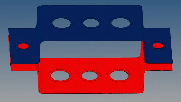
MODEL AFTER MESHING
a) Rod element:- Translational DOF should be Constrained with RBE2 link
Cross-Section: BOX- Dimension a= 12 mm
dimension b=10 mm
Thickness t= 0.75 mm
- In 1D elements select rigid---nodes---nodes by path---create notes--extract---rbe2 rigid is formed. Only transitional DoF is selected.
- Create property and name it as rod.
- In 1D elements select rods and give the required box element and its dimensions specified.
- Select the property and select beam selection as rods and card image as PROD.
- If we select the 1D detail representation we can see the full structure .
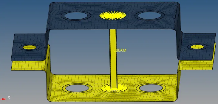
b. Beam element:- All DOF should be constrained with RBE3 link
Cross-Section: I Section- Dimension a= 8 mm
Dimension b= 10 mm
Dimension c= 8.5 mm
Thickness t1= 0.75 mm
Thickness t2= .6 mm
Thickness t3= .6 mm
- In 1D elements select rbe3---nodes---nodes by path---create notes--extract---rbe3 rigid is formed. All DOF is selected.
- Create property and name it as beam.
- In 1D elements select bar and then select CBEAM and give the required I section element and its dimensions specified.
- Select the property and select beam selection as beam and card image as PBEAM.
- If we select the 1D detail representation we can see the full structure .
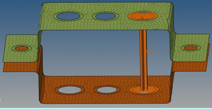
c. Bar element:- Constrain only x and y DOFs With RBE3 link
Cross-section: X section- Dimension DIM1= 5 mm
Thickness DIM2= 1.2 mm
Dimension DIM3= 10 mm
Thickness DIM4= 1.2mm
- In 1D elements select rbe3---nodes---nodes by path---create notes--extract---rbe3 rigid is formed. DOF is selected to x and y.
- Create property and name it as beam.
- In 1D elements select bar and then select CBEAM and give the required I section element and its dimensions specified.
- Select the property and select beam selection as beam and card image as PBEAM.
- If we select the 1D detail representation we can see the full structure .
d. & e. Apply the mass of magnitude 10 with the RBE2 link
- In 1D elements select rbe2---nodes---nodes by path---create notes--extract---rbe2 rigid is formed. All DOF is selected.
- In 1D element, select Masses and apply 10 magnitude and click the nodes respectively and select CMASS to apply mass respectively.
- Add prpoerty PMASS to it.
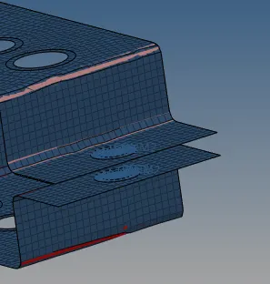
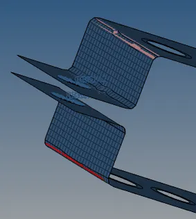
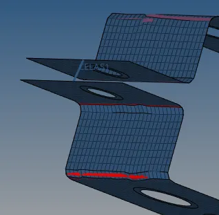
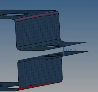
f. Join the two components with Spring elements
- In 1D element, select Springs and click the nodes respectively to apply spring respectively. Add property Pelas to it.
CONCLUSION
Every 1D element is plotted neatly and all proper dimensions are also followed.
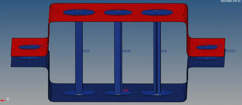
FINAL IMAGE