Week 4-1D Element Creation Challenge
CHALLENGE
AIM
To mesh the given component with a target element length of 5 units and to create 1 D connections as specified.
PROCEDURE
- First, we create the mid surface of the given component with the auto mid command.
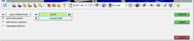
Figure1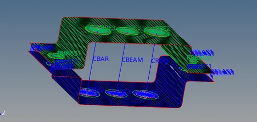
Figure 2 - We create new material for steel and assign it the Mat1 card image.Mat1 card gives the property of linear elastic, isotropic and temperature independence. Different card images give different properties to the material.
- Similarly we create 2 components for bracket1 and bracket 2 with 2 different properties for their thickness.
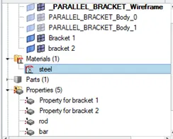
Figure3 - We assign the 2 mid surfaces to different components using the tools organize command.
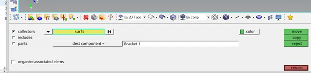
Figure4 - Now we perform auto clean up on the mid surface and create washer zones of 5mm near the holes.
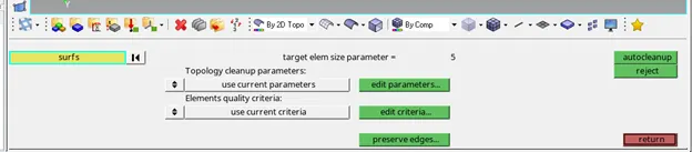
Figure5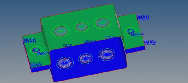
Figure 6
- The generated mid surface is meshed with the auto mesh option, we adjust the node count near the holes to prevent tria formation inside the washer region.
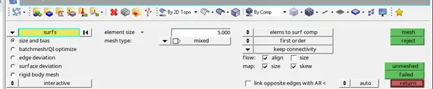
Figure 7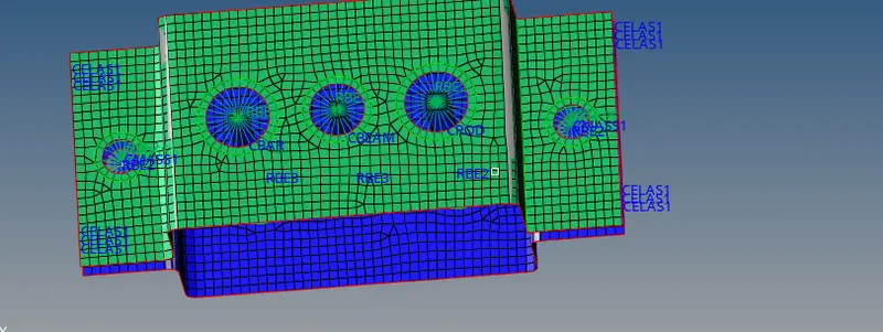
Figure 8 - After we have generated the mesh we can move to create 1D connections on the mid surface.
- We first start with Rbe2 and rbe3 connections. In the case of an RBE2, the motion observed at the independent node governs the motion that occurs at all of the dependent nodes. For example, if the independent node of an RBE2 moves by 1 mm in the X-direction, then every dependent node will also move by 1 mm in the X-direction. Because there is zero relative motion between the nodes of the RBE2, this effectively rigidizes whichever portion of your model is included within the constraint.
- Contrary to RBE2’s, whereby the behaviour of one node dictates the behaviour of many, RBE3’s work by averaging the behaviour of many nodes to determine the response at a single node. In other words, the motion of the Dependent Node of an RBE3 is calculated by taking the weighted average of the motion of the many Independent Nodes. Because there is no equation governing the relative motion between the Independent Nodes of an RBE3, this type of connection does not contribute any stiffness to the model.
- Rbe2 connections are set up with 1d->rigids option, note we select the washer zone nodes as well for connections.
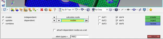
Figure 9 - Rbe3 connections are set up with 1d->rbe3 option and similar to rbe2 we select washer area nodes as well.
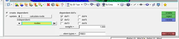
Figure10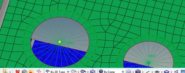
Figure11 - After setting up rbe2 and rbe3 connections we can make 1D connections for bar, beam, rod, spring and masses.
- We first make properties for rod/beam and bar. Note the card image should be Prod, Pbeam and Pbar respectively.
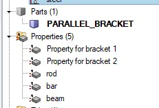
Figure12 - To set up the cross-section we go to hyper beam view and create the cross-sections as specified
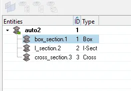
Figure 13 - Now we select the appropriate cross-section in the property for each rod/beam/bar.
- After we have made the properties we can create the connections by using 1D bars, property bars and Cbar elements for the bar
1D bars, property beam and Cbeam element for beam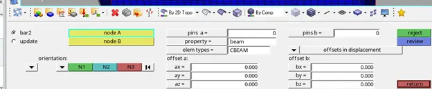
Figure 14 - For bars, 1D bars property bar and Cbar element
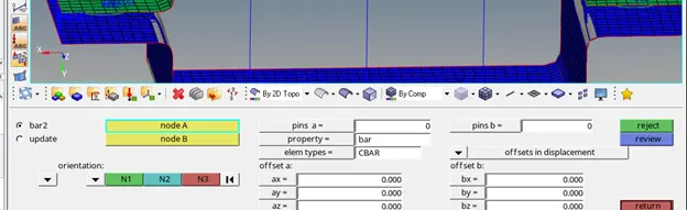
Figure 15 - For rod, we go to 1D rod, Crod and property rod
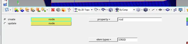
Figure 16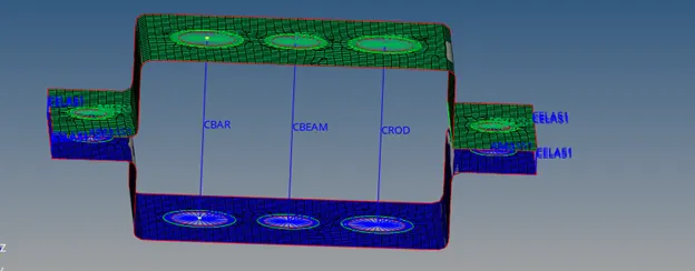
Figure 17 - For defining masses we choose Cmass1 and the centre node of the rbe2 connections.
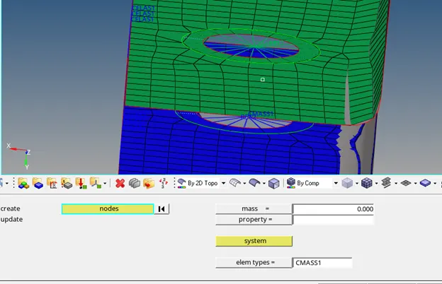
Figure 18 - Spring connections are made with 1D Springs Celas1 Element as shown.
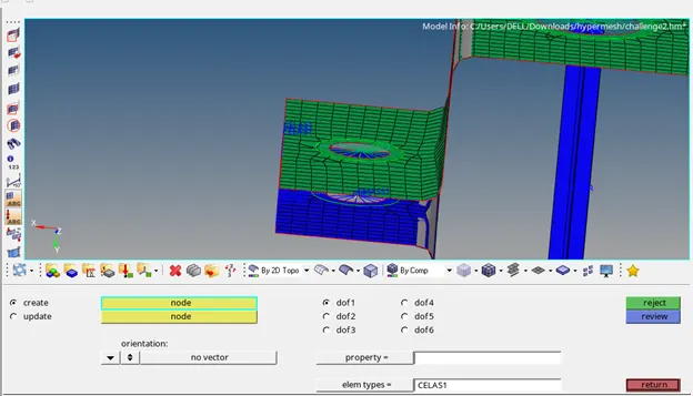
Figure 19 - After enabling 1D elements traditional and detailed view, we can see the connections with desired Cross-sectional area.
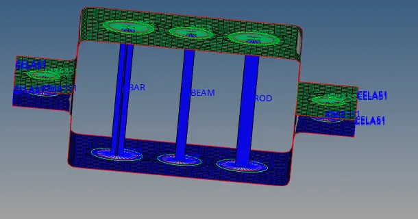
Figure 20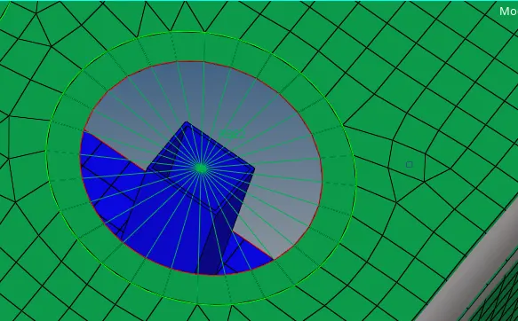
Figure 21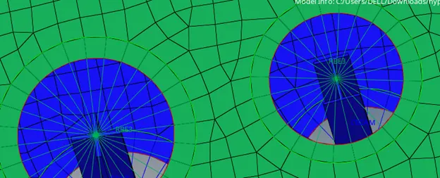
Figure 22
LEARNING OUTCOMES
- Preparing mid surface from parent geometry
- Cleanup of mid surface
- Assigning thickness to the mid surface with properties and material
- Using organize tool to assign components
- Meshing the mid surface and making rbe2 and rbe3 connections while modifying their Degree of freedom.
- Making 1D connections like Rod/bar/beam/spring and adding masses while adding cross-sectional area using properties and hyper beam view
RESULT
The mid surface of the given component was generated and then meshed. After meshing the component connections and 1D elements were deployed according to the given criteria.