Week - 4
Aim :
- To implement control logic of a “washing machine” using Stateflow as per given sequence:
- If the power supply is available, the system gets activated
- If the Water supply is not available, stop the process & indicate through LED
- Soaking time should be 200s followed by Washing time of 100s.
- Then rinsing happens for next 20s & dryer runs for 50s
After all the processes have completed turn on the finished LED
2. Make a Simulink chart for the “Gear shift” logic as per below conditions:
Speed Range(kmph) Gear
0 to 15 1
16 to 25 2
26 to 40 3
41 to 60 4
Above 61 5
Give speed input while the simulation is running & display the gear number.
Simulink Model :
1. To implement control logic of a “washing machine” using Stateflow.
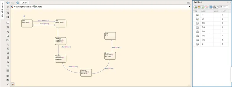
Chart for the washing machine functioning
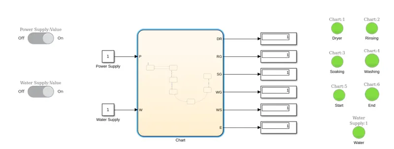
Simulink Model for washing machine functioning
When both power and water are ON.
When water is OFF
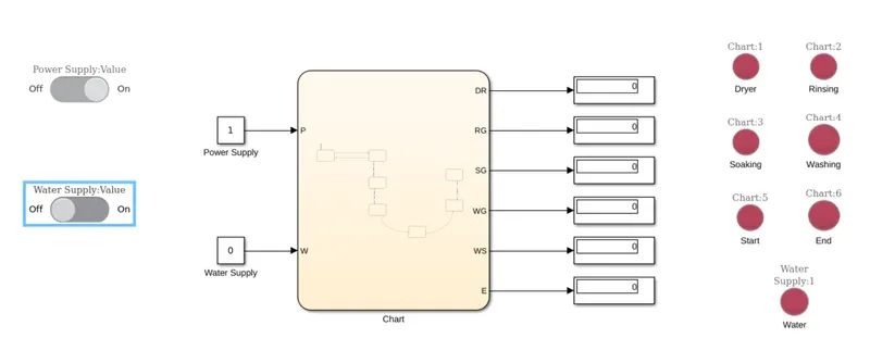
Green color or '1' - Process is complete
Red colour or '0' - Process is incomplete
The Power and water supply is controlled using the slider switch block.
The chart starts with an OFF state by default. If both power and water are available i.e the values are 1, then state is changed to ON, followed by soaking, washing, rinsing and drying.
The chart has been designed such that the respective block gives a value '1' when a particular operation is completed and '0' if it hasn't been completed.
These outputs are then used to control lamps which display the color red if the value is '0' or green if the value is '1'.
We can see that the machine runs only when both the power and water supply are available.
Hence the machine works as required.
2.
Simulink chart for the “Gear shift” logic as per below conditions:
Speed Range(kmph) Gear
0 to 15 1
16 to 25 2
26 to 40 3
41 to 60 4
Above 61 5
Give speed input while the simulation is running & display the gear number.
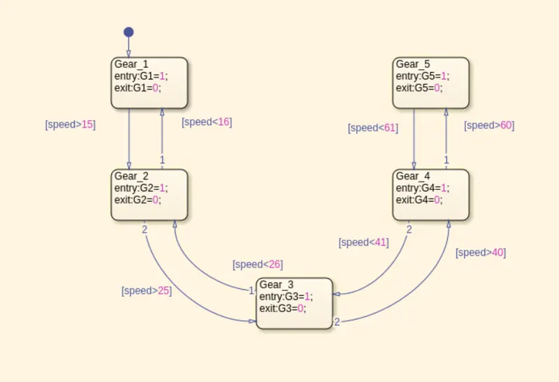
Chart for the above application
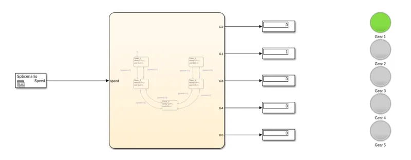
Simulink model for the above application
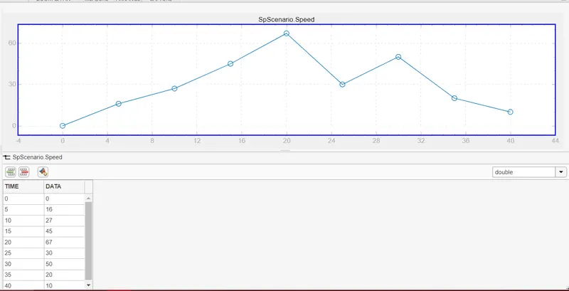
Input Speed Signal
The above chart has been designed in accordance with the requirements mentioned in the question.
The speed signal is fed into the system using a Signal Editor block.
The chart tells the user the gear currently in use via the display block as well as the indicator lamps which lights up green only if the value for the respective connected block is '1'.