MBD Simulation on IC Engine Valve Train
Aim :
- Model the parts and assemble them in SolidWorks.
- Run the simulation using the below parameters
| Sl.No | CAM Lift (mm) | Speed (RPM) | Material |
| 1 | 3.5 | 1500 | Cast Carbon Steel |
| 2 | 6 | 1500 |
Cast Carbon Steel |
Obtain the
- Valve Lift.
- The contact force between
- Cam and Push Rod
- Pushrod and Rocker Arm
- Rocker Arm and Valve
and explain why the contact force between the Rocker arm and valve varies while measuring with respect to the X direction and measuring with respect to magnitude.
Theory :
A valve train Assembly is commonly found in IC engines to let in air or a mixture of both air and fuel and also to evacuate the burnt exhaust gases. A valve train can be broadly classified into 2 types depending on the position of the cam - overhead cam Valve train and Pushrod Valve train. In an over head cam valve train the cam or cam shaft is placed over the head of the engine, above the pistons and valves. In a pushrod Valve train setup, there are long rods which have to be pushed by the camshaft lobes to move the valve rockers, which in turn open the valves.
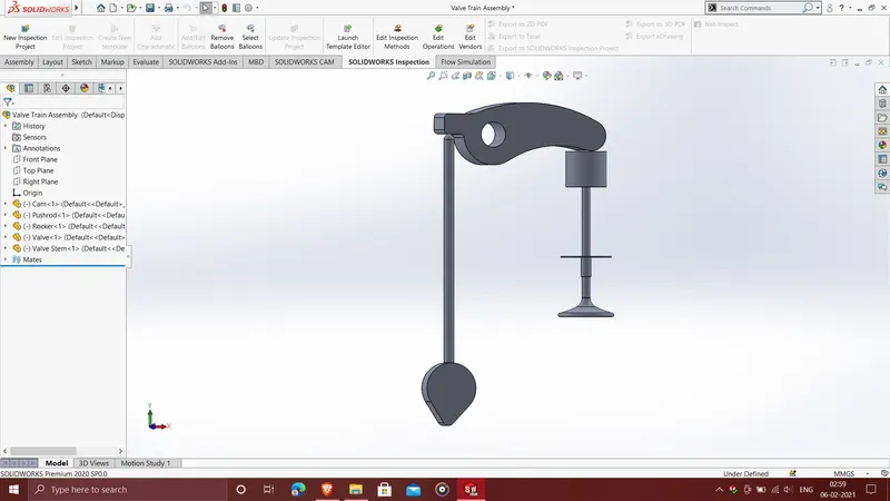
The valve train assembly dealt with here is a pushrod setup, the parts of which include a cam, pushrod, rocker arm, valve stem and valve.
Modelling and Assembly :
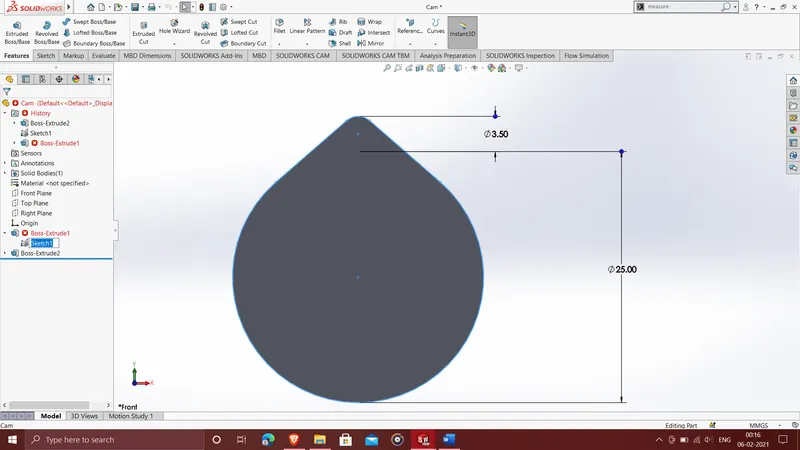
Cam Profile for Case 1
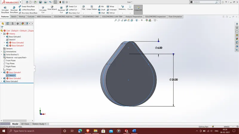
Cam Profile for Case 2 :
Final Assembly
Results :
Case 1 : Cam Lift = 3.5mm
Valve lift
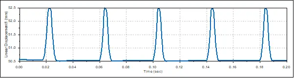
Valve Lift = 2mm
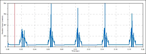
Contact Force between Cam and Pushrod (Magnitude)
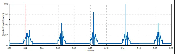
Contact Force between Pushrod and Rocker Arm (Magnitude)
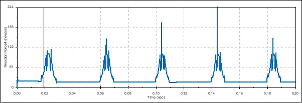
Contact Force between Rocker Arm and Valve (Magnitude)
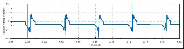
Contact Force between Rocker Arm and Valve (X-direction)
Case 2 : Cam Lift = 6mm
Valve lift
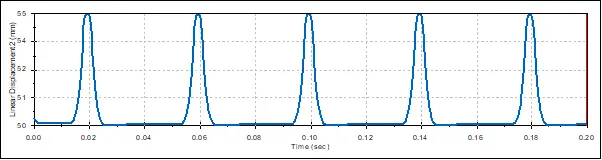
Valve Lift = 5 mm
Contact Force between Cam and Pushrod (Magnitude)
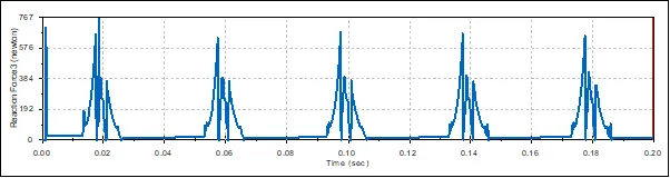
Contact Force between Pushrod and Rocker Arm (Magnitude)
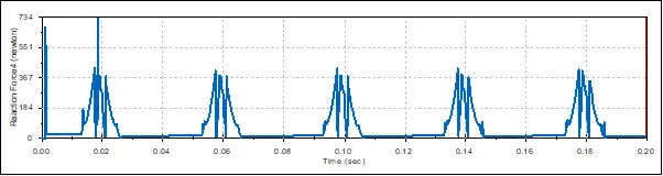
Contact Force between Rocker Arm and Valve (Magnitude)
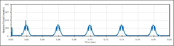
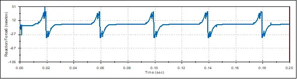
Contact Force between Rocker Arm and Valve (X-direction)
Conclusions :
1. The plots for Valve Lift and contact forces between the various parts are shown above.
2. There is a difference in the plots of Contact force between the Rocker arm and Valve depending on the component that was chosen.
3. When we chose "magnitude" the plot shows the net force acting between the rocker and the valve. Choosing, X-direction however shows the force acting in the x- direction which is primarily the frictional force acting as the rocker arm surface slides over the top of the valve. The plot first shows a spike in the postive x-axis direction and then a similar spike in the negative x-axis direction as the direction of the frictional force changes during the simulation. The change in direction of the force is because the rocker arm first slides towards origin giving a positive frictional force (opposing the motion) and then slides away from the origin giving rise to a frictional force in the negative x-direction. Therefore the plots are opposite to each other.