MBD Simulation on a Piston Assembly
Aim :
Model all the parts and then assemble them in SolidWorks and carry out the motion analysis in three different conditions,
| Sl.No |
Wrist Pin Offset ` |
Crank Speed (Rpm) |
| 1 | "0" mm | 2000 |
| 2 | 10 mm Positive | 2000 |
| 3 | 10 mm Negative | 2000 |
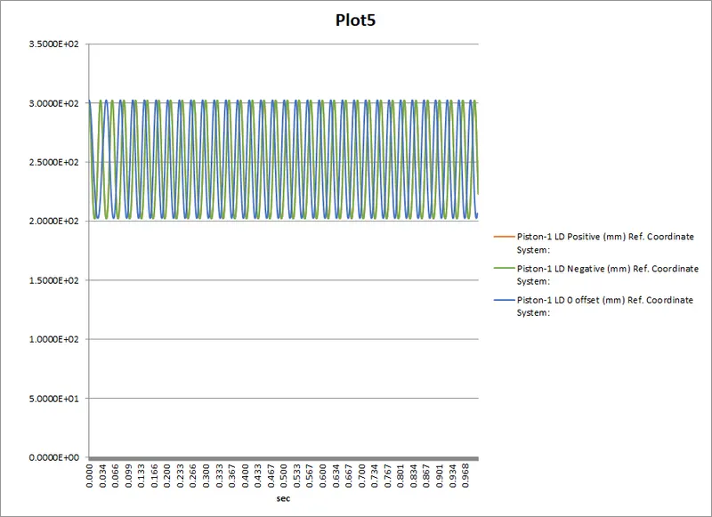
Obtain the Linear displacement of the Piston Head in all the three cases. Then export the graphs into Excel. Then Superimpose all the three graphs into a single graph.
Theory :
A piston assembly typically consists of a piston, wrist pin or gudgeon pin, connecting rod (divided into 2 parts connecting rod and end cap for ease of assembly) and a crank. This assembly essentially converts the up and down reciprocating motion of the piston into a rotational motion of the crank. A piston assembly is primarily used in IC engines where the energy produced by burning fuel and air is used to push the piston down and rotate the crank shaft.
A piston assembly can also be found in a mechanical pump to pump any fluid. In this case, the rotational motion of the crank is converted into a reciprocating motion of the piston. The head of the piston compresses or ejects the fluid as it reaches TDC and draws in fresh uncompressed fluid as it reaches BDC.
Modelling and Assembly :
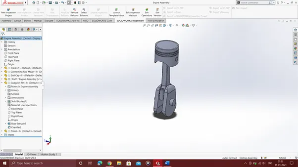
The various part drawings were used for the modeling and assembly of all the parts.
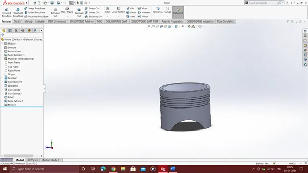
Piston
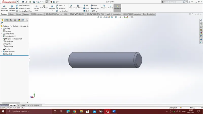
Wrist pin
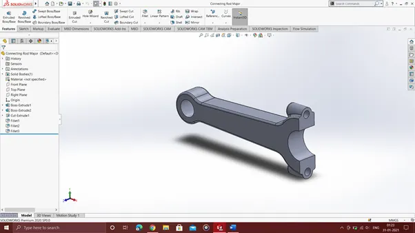
Connecting rod
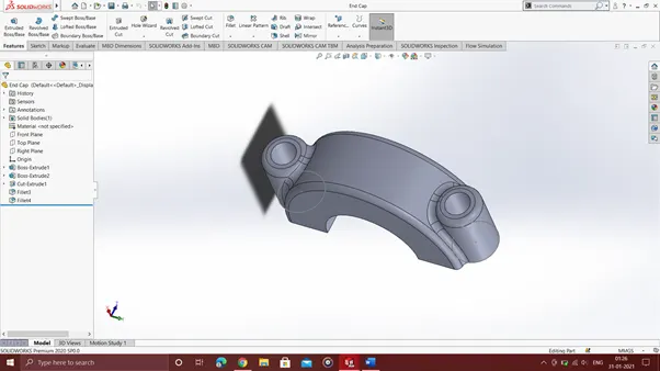
End Cap
Final Assembly
Motion Analysis :
The motion analysis of the assembly was carried out by using the "Motor" option to give a rotational motion of 2000 rpm to the crank shaft. All the required contacts between the parts were defined using the "Contacts" option and Gravity was defined along the Y Axis (downward). Following this the simulation was carried out, and the required plots and results were obtained.
Plots and Results :
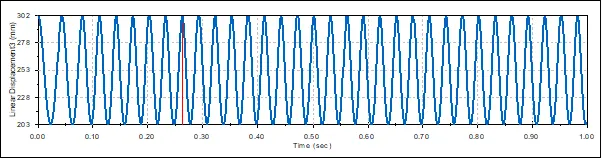
Zero Offset
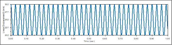
Postive 10mm Offset
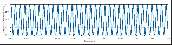
Negative 10mm Offset
Superimposed view :
Conclusions:
1. The curve showing the linear displacement of the piston follows a sinusoidal trajectory and oscillates between the same maximum and minimum points throughout the period of the simulation.
2. The values for the maximum and minimum heights achieved by the piston varies between the cases and 0 offset and 10mm positive and negative offset. The variation is however very minimal and cannot be visually detected in the plot.
0 offset
Maximum : 302.50mm Minimum : 202.50mm Stroke Length = 100mm
10mm positive offset
Maximum : 302.31mm Minimum : 202.19mm Stroke Length = 100.12mm
10mm Negative offset
Maximum : 302.31mm Minimum : 202.19mm Stroke Length = 100.12mm
3. The theoretical maximum stroke length is twice the crank radius, which is 2*50 = 100mm. From the above data we can see that the actual stroke is more or less consistent with the theoretical data.
4.. in the case of 0 offset at TDC and BDC the gudgeon pin is directly above the crank i.e the axis of the gudgeon pin is line with the crank axis and hence would require more energy to rotate the crank than in the case of either a negative or a positive offset.