Internal Geneva Mechanism
Aim:
- Create 3D models for driver and driven wheels.
- Perform motion analysis by rotating the driver wheel at 10rpm.
- Obtain the following plots
- Contact force (between driving and the driven wheel) as a function of time.
- Angular Displacement of the driven wheel.
- Compare the contact forces with and without "Precise contact"
- Show image for precise contact selection
- Export the results that you get to Excel and make the plots over there
- Use 60 Frames per second for 10 rpm and then 120 Frames per second for 20 Rpm
- Make a plot of the driver wheel's angular velocity and
Introduction : The internal Geneva mechanism is a device wherein a continuous rotational motion of the driver wheel is converted into an intermittent motion of the driven wheel. This is achieved by the sliding of the pin of the driven wheel in the slots of the driven wheel. This mechanism is used in the Turret lathes and other machines where tools or devices need to be channged periodically to perform various tasks. There are 3 types of Geneva mechanisms - internal, external and spherical.
The number of slots in the driven wheel determine its angle of rotation for every complete rotation of the driver wheel. If, for example, the driven wheel has 4 slots, the driven wheel will be rotated by 90 degrees for every 360 degrees rotated by the driver wheel.
Modelling and Assembly:
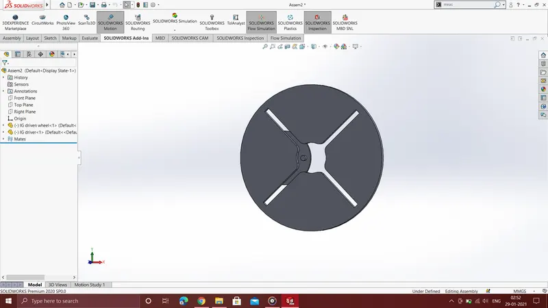
The Assembly of the internal Geneva mechanism having 4 slots is as shown below
Results :
10 RPM
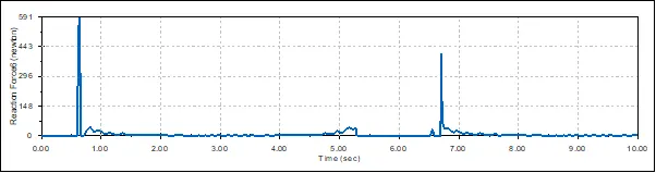
Contact force between driver and driven wheels at 10 RPM without precise contact
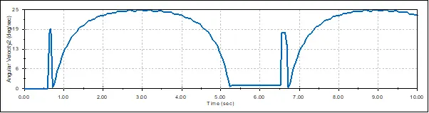
Angular velocity of driven wheel at 10 rpm without precise contact
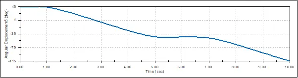
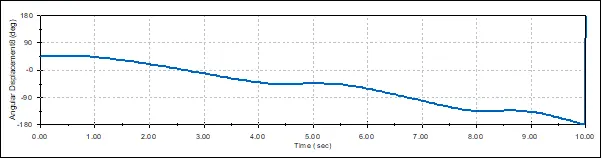
Angular displacement of driven wheel at 10 rpm without precise contact
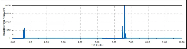
Contact force between driver and driven wheels at 10 RPM with precise contact at 60 FPS
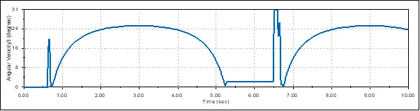
Angular velocity of driven wheel at 10 rpm with precise contact at 60 FPS
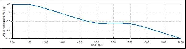
Angular displaceent of driven wheel at 10 rpm with precise contact at 60 FPS
20 RPM
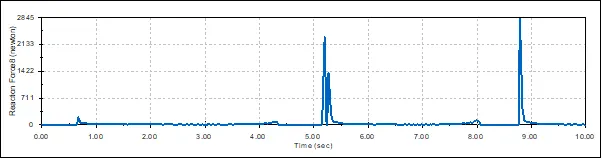
Contact force between the wheels at 20 rpm without precise contact
Angular velocity of driven wheel at 20 rpm without precise contact
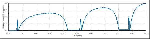
Angular displacement of driven wheel at 20 rpm without precise contact
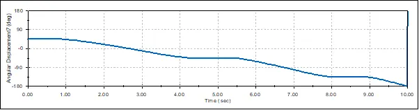
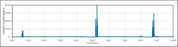
Contact force between the wheels at 20 rpm with precise contact at 120 FPS
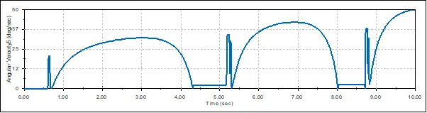
Angular velocity of driven wheel at 20 rpm with precise contact at 120 FPS
Angular displacement of driven wheel at 20 rpm with precise contact at 120 FPS
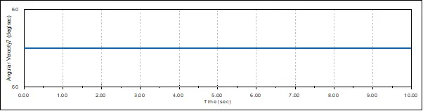
Angular Velocity of Driver wheel
Angular velocity of Driver Wheel at 10 RPM with Precise contact at 60 FPS
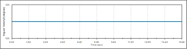
Angular velocity of Driver Wheel at 20 RPM with Precise contact at 120 FPS
Conclusions :
1. It can be seen from the graphs and plots obtained that using the "Precise Contact" option gives us a much smoother plot. The values hence obtained are definitely more consistent and accurate and can be relied on more compared to the plot obtained without using "Precise Contact".
2. The entry of the driver wheel pin into the slots of the driven wheel is a bit jerky and this corresponds to a spike in the respective Contact Forces Plot, representing a sudden increase in contact force at that instant.
3. The Angular velocity of the driven wheel increases linearly with the RPM of the driver wheel.
4. As is visible from the plot, the Angular velocity of the driven wheel spikes when the driver wheel pin enters the slot of the driven wheel ( due the jerk caused ). If we then follow the plot we see the angular velocity slowly increase, peak and then fall down to 0 and the process then repeats itself. the driven wheel achieves maximum angular velocity when the driver wheel pin reaches the outter most point of the driven wheel's slot.
5. Angular velocity of the Driver wheel remains constant throughout the entire simulation.
5. The Angular displacement of the wheels vary between -180 degrees and 180 degrees, while starting from 0 degrees.