Week - 4
- Implement control logic of a “washing machine” using Stateflow as per given sequence:
- If the power supply is available, the system gets activated
- If the Water supply is not available, stop the process & indicate through LED
- Soaking time should be 200s followed by Washing time of 100s.
- Then rinsing happens for next 20s & dryer runs for 50s
After all the processes have completed turn on the finished LED
Ans:
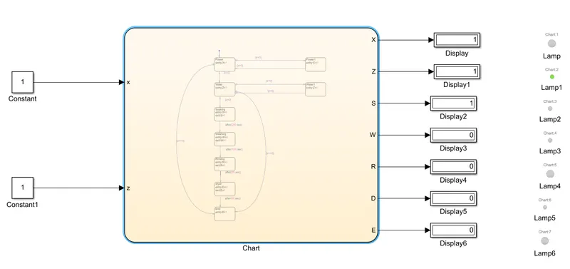
Simulink model:
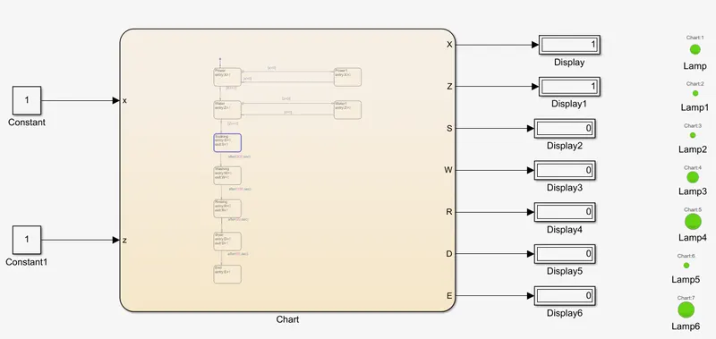
Fig.1 Simulink model of washing machine
Working of washing machine:
Soaking:
The washer not immediately to wash when added the detergent, but the washer will be intermittent rotation, because there have a soak time, and the washing machine automatically start washing when the soak time has elapsed.
Washing:
Washing machine is the machine used to wash the various types of clothes without applying any physical efforts. With washing machine you don't have to rub the clothes with hand or squeeze them to remove the water from them. The washing machine is also called as clothes washer or simply the washer.
Rinsing:
The dirty, soapy water is drained, then the washing machine is refilled and your clothes are "rewashed" in clean water. Spin: All the water is drained completely, then your clothes are spun very fast and excess water is removed thanks to centrifugal force.
Dryer:
Air is drawn into the dryer through openings or vents on the outside of the housing. The air is heated and distributed throughout the drum by a fan or blower. The heated air helps to draw the moisture from the clothing. ... As the air is dried, it is reheated and passed through the clothes again.
State model:
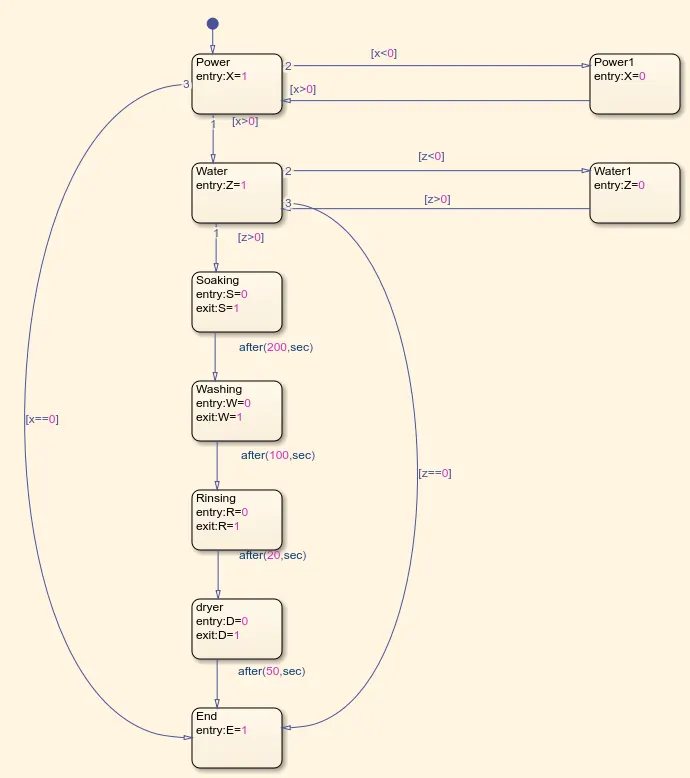
Fig.2 Chart diagram using state blocks
For Power and Water supply two inputs are given, once the both inputs are available the soak function will start its working and it display the result in the form of lamp. Each state block will display the result as per the sequence of state.
Input and Output table from Symbols pane:
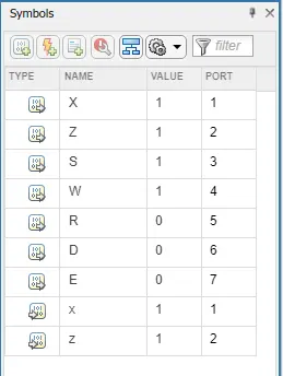
Fig.3 Symbol pane chart
In this chart we are giving the input and output ports as we required for washing machine.
Here what input we have named to the state block the same name is in NAME column otherwise it shows a error.
Result:
After all the process the LED becomes turn ON:
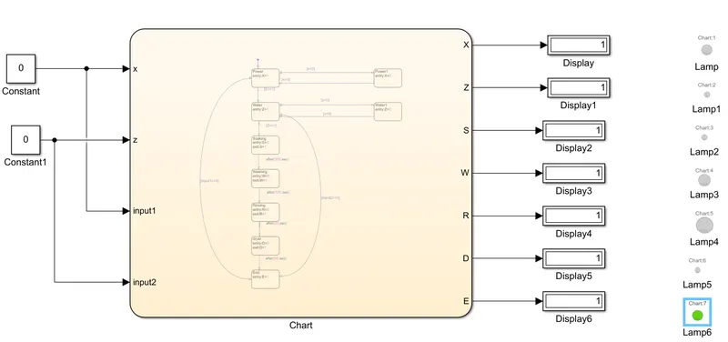
Soaking process when Stop time is 200 seconds
------------------------------------------------------------------------------------------------------------------------------------------------
2. Make a Simulink chart for the “Gear shift” logic as per below conditions:
Speed Range(kmph) Gear
0 to 15 1
16 to 25 2
26 to 40 3
41 to 60 4
Above 61 5
Give speed input while the simulation is running & display the gear number.
Ans:
Simulink chart for Gear shift:
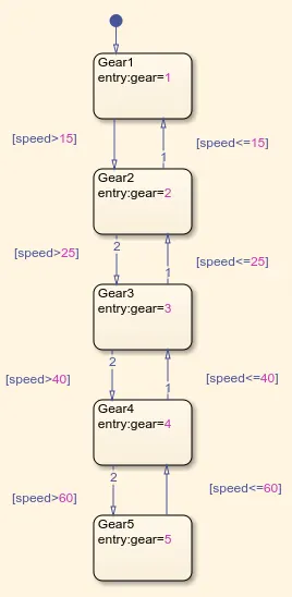
Fig.1 Simulink chart for Gear shift
Here we used five different speed limits for five gears. Each gear system is showed by simple block in chart is called state block. In this there are 5 spee limits are given so we used five gear shifts in each block. When the speed goes above 15kmph then only the gear shifts from gear1 to gear2. Like wise all the gears are shifting according to the speed limits.
Explanation:
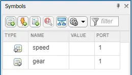
Fig.2 Symbol pane chart
For the above question we need to give one input for speed and one output for gear.
The slider gain is used to vary the speed and display block is helps to finding in which gear the vehicle is moving.
- Constant:
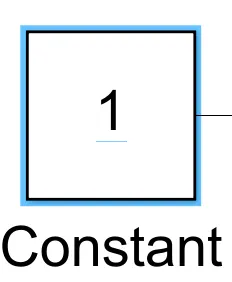
Output the constant specified by the 'Constant value' parameter. If 'Constant value' is a vector and 'Interpret vector parameters as 1-D' is on, treat the constant value as a 1-D array. Otherwise, output a matrix with the same dimensions as the constant value.
- Slider Gain:
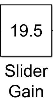
The Slider Gain block performs a scalar gain that you can modify during simulation. Modify the gain using the slider parameter.
- Display:
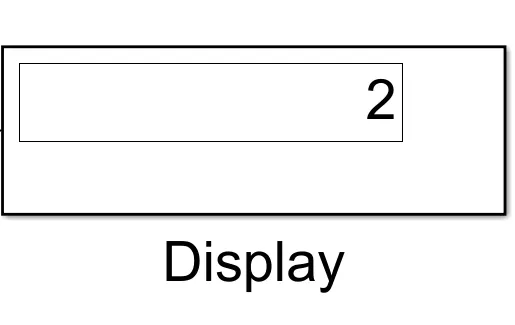
Display input values. If the incoming signal is of type string, the 'Numeric display format' parameter selection does not affect the display of the string.
Results:
Simulink models:
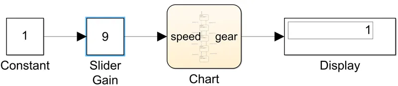
When engine is starting and speed is in 9 kmph during that period the first gear is running as per the given condition.
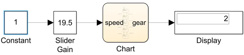
For 19.5 kmph speed the gear will be running in second gear.
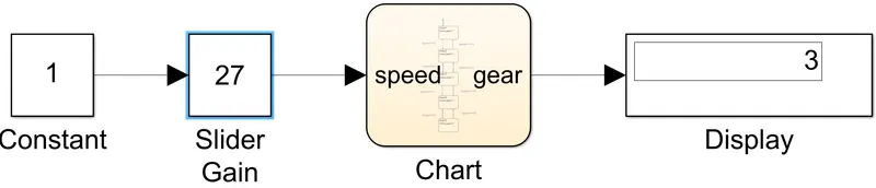
For 27 kmph speed the gear shifts from second to third as per the condition.

When speed is in between 45-60 kmph that period 4th gear is operates.
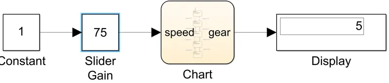
When speed comes to 75 kmph the gear shifts to 5th gear.