Week -2
- Make a Simulink model of Doorbell using solenoid block with the following details:
In the above arrangement, when the switch is closed the electromagnet receives electrical power from the battery and pulls the metal arm to hit the bell producing sound.
Create a situation where the switch is closed for 2 seconds and then released. Observe the physical movement of the plunger.
Ans: 1. Door Bell
Simulink model:
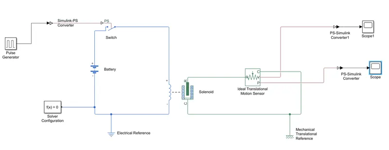
Fig.1 Simulink model of Door bell
Explanation:
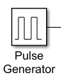
- Pulse generator is used as input to create square wave pulse and here we changed the period, pulse width and phase delay as shown in the below image.
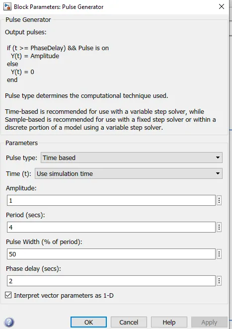
-
The switch block is controlled by an external physical signal. If the external physical signal PS is greater than the threshold, then the switch is closed, otherwise the switch is open.
- The positive terminal of the battery is connected to positive sign of switch and negative is connected to electrical reference.
- Solver configuration block is defines solver settings to use for simulation.
- The Electrical Reference block represents an electrical ground. Electrical conserving ports of all the blocks that are directly connected to ground must be connected to an Electrical Reference block. A model with electrical elements must contain at least one Electrical Referenceblock.
- Solenoid: This block implements the electrical and mechanical characteristics of a solenoid.
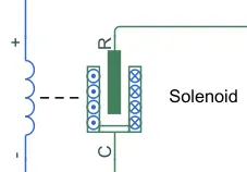
The plunger Maximum stroke is implemented as a hard stop, the dynamics of which are set by the Contact stiffness and Contact damping parameters. The same parameters are used to model the contact dynamics when the plunger pulls fully in. The Spring constant parameter is used to implement a spring force that pulls the plunger out, and can be set to zero.
-
Ideal Translational Motion sensor: This block measures velocity or displacement in a mechanical translational network.
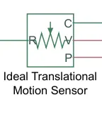
The sensor is ideal since it does not account for inertia, friction, delays, energy consumption, and so on. The physical signal ports V and P report the displacement and velocity, respectively, of port R relative to port C. The measurement is positive when the motion at R is greater than the motion at C.
- Mechanical Reference:

This block represents a mechanical translational reference point, that is, a frame or a ground. Use it to connect mechanical translational ports that are rigidly affixed to the frame (ground).
- Electrical Reference:

Electrical reference port. A model must contain at least one electrical reference port (electrical ground).
- Battery:

This block models a battery. If you select Infinite for the Battery charge capacity parameter, the block models the battery as a series internal resistance and a constant voltage source. If you select Finite for the Battery charge capacity parameter, the block models the battery as a series internal resistance plus a charge-dependent voltage source.
- Switch:
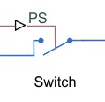
The block represents a switch controlled by an external physical signal. If the external physical signal PS is greater than the threshold, then the switch is closed, otherwise the switch is open.
- PS-Simulink Converter and Simulink-PS Converter:
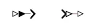
Converts the input Physical Signal to a Simulink output signal and Simulink to output physical signal respectively.
- Solver Configuration:
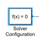
Defines solver settings to use for simulation.
- Scope:
It is used as output block which will give us result of simulink model in the form of wave.
Result:
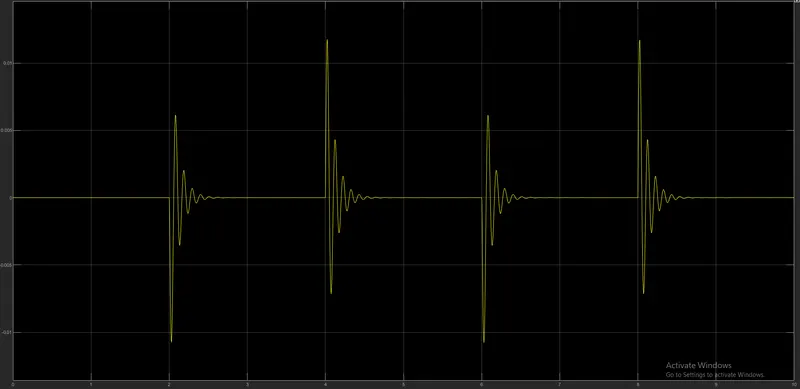
Fig.2 Output of Displacement
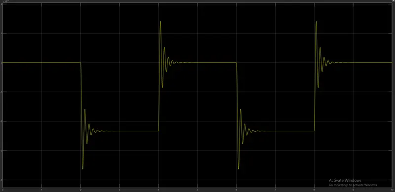
Fig.3 Output of Velocity
Conclusion:
From this model we came to know that here time period is given as 2 seconds to the pulse generator to open and close the switch. For every 2 seconds the pendulum moves from left to right and right to left respectively. When the switch is closed that time solenoid recieves the power from the battery and it makes sound.
--------------------------------------------------------------------------------------------------------------------------------------------------------------------
2. Use a thermistor to sense the temperature of a heater & turn on or turn off the fan as per below conditions:
Temperature source: 20 °C from 0 to 10 seconds, 27 °C from 10 to 30 seconds, 23 °C from 30 to 50 seconds
Fan conditions: ON if the temperature above 25 °C, OFF otherwise
Ans:
Simulink Model:
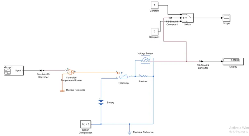
Fig.1 Simulink model of Fan Control using Thermistor
Explanation:
- Signal Builder:
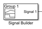
The Signal Builder block allows us to create interchangeable groups of piecewise linear signal sources and use them in a model. We can quickly switch the signal groups into and out of a model to facilitate testing. In the Signal Builder window, create signals and define the output waveforms.
- Controlled temperature source:
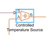
This block represents an ideal energy source in a thermal network that can maintain a controlled temperature difference regardless of the heat flow rate. The temperature difference is set by the physical signal port S. A positive temperature difference causes the temperature at port B to be greater than the temperature at port A.
- Thermistor:
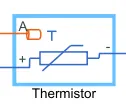
The Thermistor block represents an NTC thermistor using the B-parameter equation. The Variables section of the block interface to set the priority and initial target values for the block variables prior to simulation.
- Battery:

This block models a battery. If you select Infinite for the Battery charge capacity parameter, the block models the battery as a series internal resistance and a constant voltage source. If you select Finite for the Battery charge capacity parameter, the block models the battery as a series internal resistance plus a charge-dependent voltage source.
- Voltage Sensor:
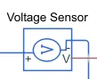
The block represents an ideal voltage sensor, that is, a device that converts voltage measured between any electrical connections into a physical signal proportional to the voltage.
- Thermal Reference:

This block represents a reference point in a thermal network where the temperature is equal to absolute zero.
- PS-Simulink and Simulink-PS Converter:
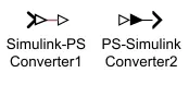
Converts the input Physical Signal to a Simulink output signal and Simulink input signal to a Physical Signal respectively.
- Resistor:

This block models a resistor with optional tolerance, operational limits, fault and thermal noise modeling. To model temperature effects, select the thermal variant of this block by right-clicking on the block and selecting Simscape block choices and Show thermal port.
- Electrical Reference:

Electrical reference port. A model must contain at least one electrical reference port (electrical ground).
- Constant:

Output the constant specified by the 'Constant value' parameter. If 'Constant value' is a vector and 'Interpret vector parameters as 1-D' is on, treat the constant value as a 1-D array. Otherwise, output a matrix with the same dimensions as the constant value.
- Scope:

Display signals generated during simulation
- Display:
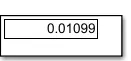
The Display block shows the value of the input data. You can specify the frequency of the display. For numeric input data, you can also specify the format of display.
Result:
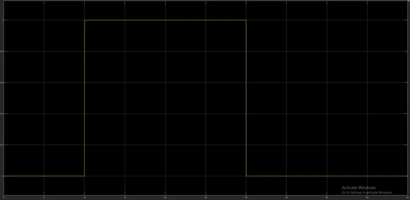
Fig.2 Output wave form of Fan controlled using Thermistor
Conclusion:
Here the time duration is takened 50 seconds, in that from 0-10sec the fan is in off condition due to temperature was below 25 degree celcius. And during 10-30sec the temperature goes to 27 degree celcius so according to given condition the fan must be in on condition. From 30-50sec the fan again goes to off condition due to temperature is in below 25 degree celcius.
--------------------------------------------------------------------------------------------------------------------------------------------------------------------