Week - 4
Aim: Implement control logic of a “Washing Machine” using Stateflow as per given sequence:
If the power supply is available, the system gets activated.
If the Water supply is not available, stop the process & indicate through the LED.
Soaking time should be 200s followed by Washing time of 100s.
Then rinsing happens for the next 20s & dryer runs for 50s.
After all the processes have been completed turn on the finished LED.
Block Diagram and Description:
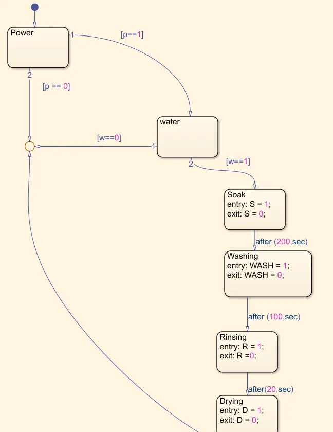
1. A chart is created determining the various state flows of the washing machine such as filling the water for 30 sec, Soaking for 200
sec, Washing time for 100 sec, Rinsing for 20-sec snd then drying for 50 sec.
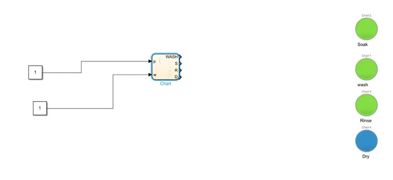
2. LED lamps are connected to show progress in every state.
3. Water supply is checked before the soaking process and if there is no water supply the situation is indicated through a LED lamp
and the washing machine is turned off.
4. At last the washing machine is turned off and it is indicated using another LED lamp.
The Control Chart
The Main Program
Results: Therefore control logic of a Washing machine is executed.
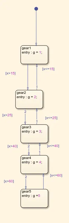
Objective 2:- Make a Simulink chart for the “Gear shift” logic as per the below conditions:
Speed Range(km) Gear
0 to 15 1
16 to 25 2
26 to 40 3
41 to 60 4
Above 61 5
 State Flow logic Chart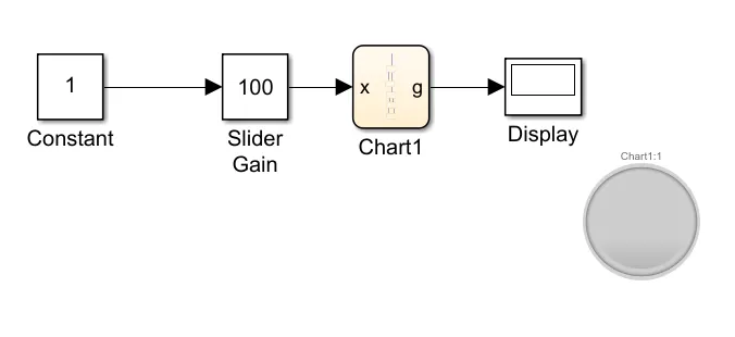
The gearbox model uses a slider as a speed input inorder to simulate the throttle, and gauge connected to the same signal
to display the inputted speed value, the output is then displayed on a display, and scope is connected to see the
speed and gearshift outputs.
Steps:
1)-At first gear is selected and the car will remain in this gear until the speed exceeds 15.9kmphthen it will shift to the second
gear, and as the system is exiting this state it will disengage the first gear.
2)-On the other hand if the vehicle was in second gear and decelerated to less than 15.9 mph, the system will make the shift to the
first gear and as it is exciting from the second state it will disengage the second gear.
3)-Then it will shift to third when the speed is higher than 25.9 kmph gear, and as the system is exiting this state it will disengage
the second gear.
4)-On the other hand, if the vehicle was in third gear and decelerated to less than 25.9 mph, the system will make the shift to the
second gear and as it is exiting from the third state it will disengage the third gear.
5)-Then the speed exceeds 40.9 kmph then it will shift to the fourth gear, and as the system is exiting this state it will disengage
the third gear.
6)-On the other hand, if the vehicle was in fourth gear and decelerated to less than 40.9 km mph, the system will makeshift
to the third gear and as it is exiting from the fourth state it will disengage the fourth gear.
7)-then when the speed exceeds 60.9kmph then it will shift to the fifth and final gear, and as the system is exiting this state it will
disengage the fourth gear.
8)-On the other hand, if the vehicle was in fifth gear and decelerated to less than 60.9 mph, the system will make the shift to the
fourth gear and as it is exiting from the fifth state it will disengage the fifth gear.
9)-All the output is stored in the same variable to be able to display all the gear shifts on a single display
10)-The stop time is made to inf to enable user control of speed while the simulation is running.
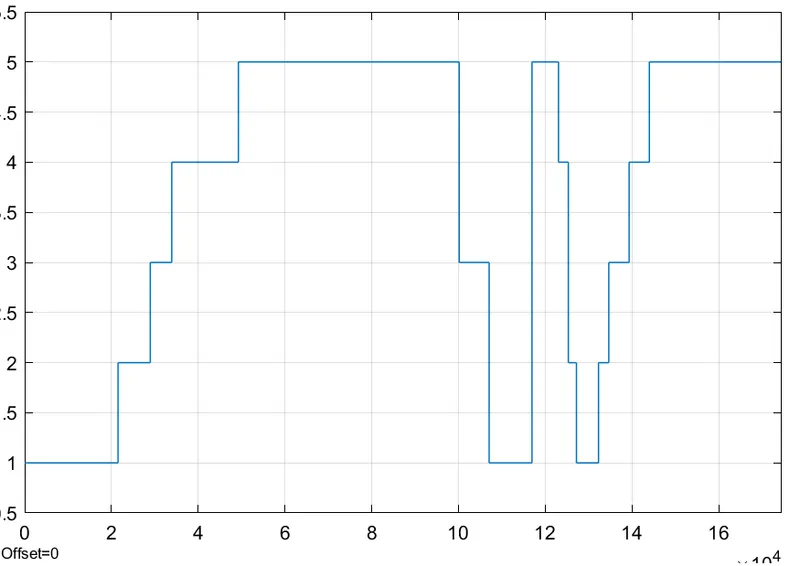
The gearbox transmission Graph.
Initially, first gear is selected, then at speed of 16 km/h it shifted to second gear, then at speed of 26 km/h it shifted to third gear
then at speed of 41 km/h it shifted to fourth gear then at speed of 61 km/h it shifted to fifth gear, and it remained at this gear
even with the speed increasing and reaching 100kmph.