Week - 4
TO MAKE SIMULINK MODEL FOR GIVEN OBJECTIVES
AIM: Implement control logic of a “washing machine” using Stateflow as per given sequence.
OBJECTIVE 1:
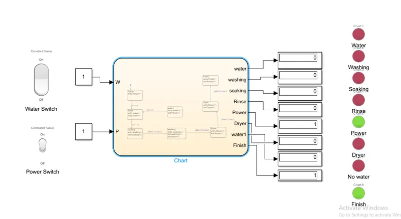
- If the power supply is available, the system gets activated
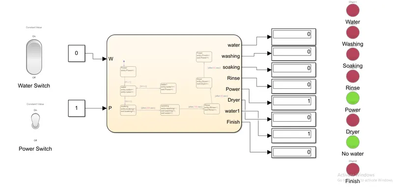
- If the Water supply is not available, stop the process & indicate through LED
- Soaking time should be 200s followed by Washing time of 100s.
- Then rinsing happens for next 20s & dryer runs for 50s
Procedure:
- Create a chart in simulink that consists of 8 blocks which denoted as Power,water,soaking,washing,Rinse,Dryer,Finish and no water supply.
- Apply the syntax for the given blocks as per the given conditions above.
- Add an input source for two blocks such as water and power supply.
- Add switches from the simulink library which creates the value as 0 for OFF and 1 as ON condition.
- Set the outputs for the parameter blocks in order to glow a bulb or an LED when the current process takes place.
Block Diagram:
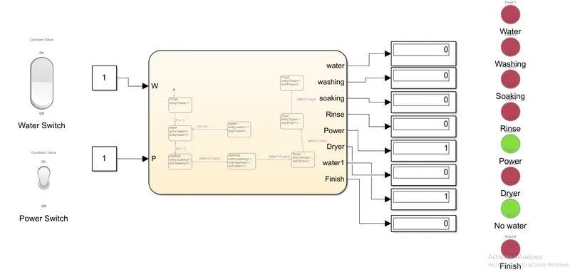
Chart Diagram:
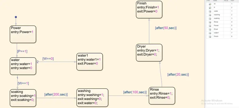
Objective 2: Make a Simulink chart for the “Gear shift” logic as per below conditions and give speed input while the simulation is running & display the gear number
Speed Range(kmph) Gear
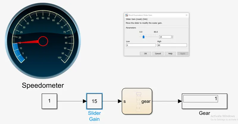
0 to 15 1
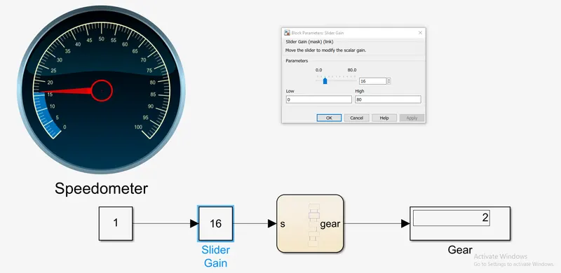
16 to 25 2
26 to 40 3
41 to 60 4
Above 61 5
Procedure:
- Create a chart in the simulink GUI and add 5 blocks in the chart in which each gear ratio is defined as per given speed.
- Add the logic of speeds as per the given conditions as shown in the below block diagram.
- Add input from a slider gain and Circular gauge from simulink library browser.
- Connect the output from the display block which shows the gear indicator.
Block diagram:
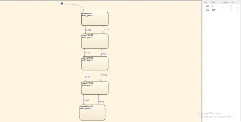
Results:
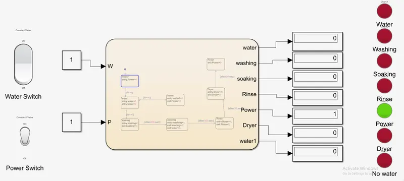
Objective 1:
Case 1 (when power and water supply is ON)
Case2 (when SOAKING)
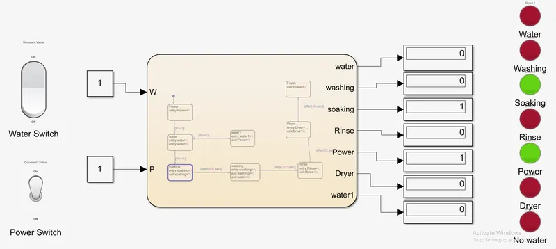
Case 3 (when washing)
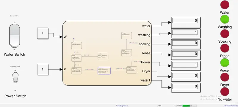
Case 4(when Rinsing)
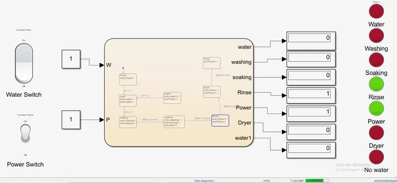
Case 5(When dryer is ON)
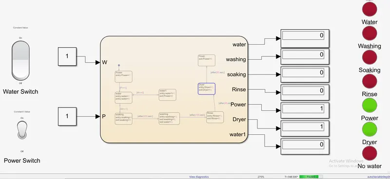
Case 6(when Process is finished)
Case 7 (when power is ON and Water is not supplied)
Objective 2:
Case 1 (1st gear)
CASE 2(2ND GEAR)
Case 3(3rd gear)
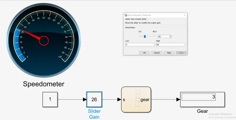
Case 4(4th gear)
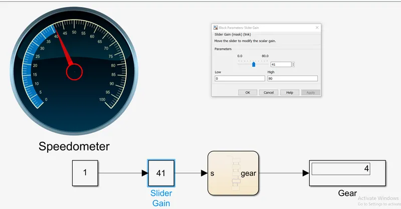
CASE 5(5TH GEAR)
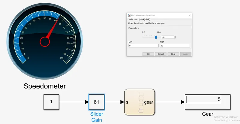
CONCLUSION:
Thus the required outputs for the objectives are obtained.