Project
SIMULATION OF AN ALL TERRAIN VEHICLE USING CVT TRANSMISSION
AIM: To run a simulation of an all terrain vehicle(BAJA) using a CVT transmission.
Objectives:
- Preparing a technical report of an ATV
- Run a simulation of a CVT Transmission used in ATV and obtain outputs.
WORKFLOW:
Download BAJA ATV simulink model from mathwork website>>
Dividing subsystems and by the working procedure>>
Divide CVT model and CVT dashboard model for changing outputs >>
Creating the report for subsystems and their logic.
BAJA ALL TERRAIN VEHICLE(ATV) MODEL:
BAJA ATV is a developed four wheel model to sustain any road conditions for different type road events such as Sprint,Endurance etc. The developed ATV model can result in depicting parameters such as Reliability,Safety,efficiency of developed ATV.
Image:
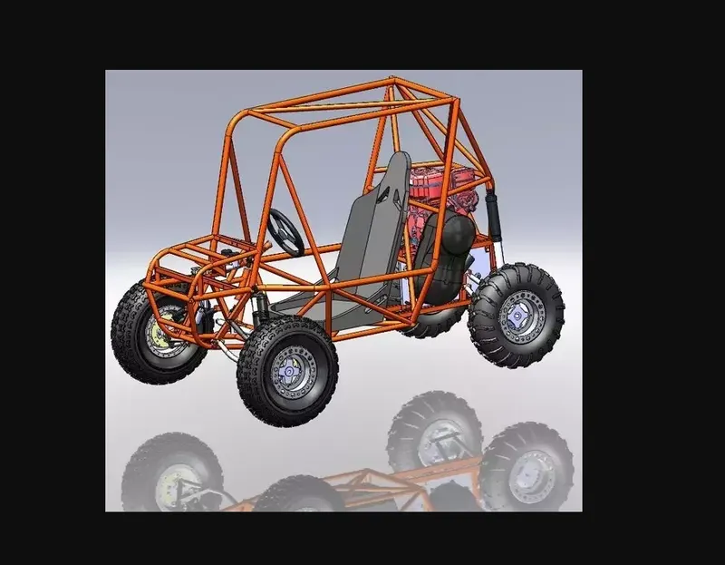
The above shows exactly what an ATV looks like which is most common seen.
Simscape and simulink have been used to complete the system. The engine specifications are also provided.
This report contains a set of models created with Simulink and Simscape.This report also includes the working and explanation of a BAJA ATV model with Continuously variable Transmission(CVT).
Difference between an CVT and Automatic Transmission:
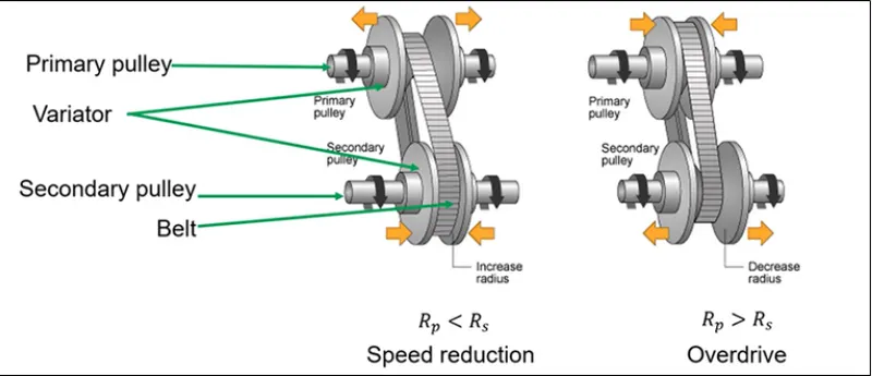
CVT is a continuously variable transmission which varies by a vehicle instantaneously with respect to its speed. In this transmission there are no gears that need to shift between low and high speeds. Instead, its works as a pair of variable diameter, cone-shaped pulleys which are connected by a metal or composite belt.
Images:
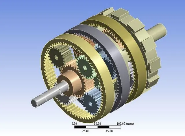
Where as in an automatic transmission there are different gears arranged in a planetary gear system which actuates to appropriate gear by the vehicle speed. Its arrangement is complex when compared to an CVT system
Images:
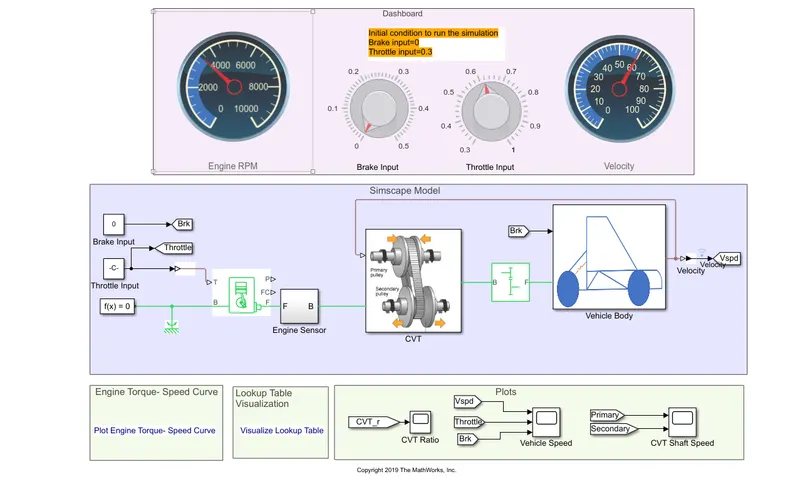
Simscape model of an ATV:
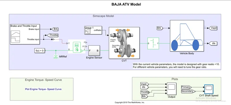
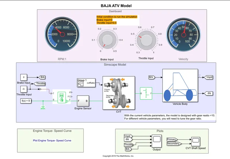
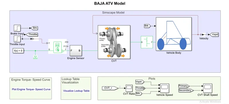
From the above image the components present are vehicle body,CVT,Generic Engine,Simple Gear,Input blocks.
INPUT BLOCKS:
Images:
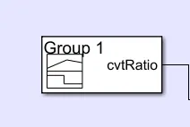
The CVT ratio is gained from data lookup table:
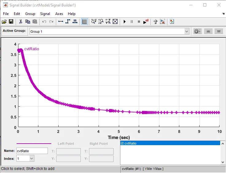
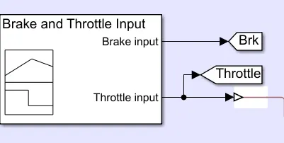
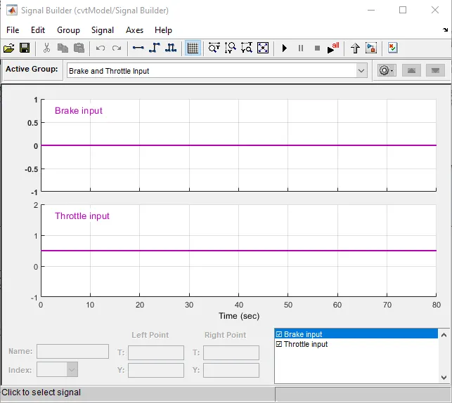
Two different signal builders are required in this ATV model. First one inputs the variable throttle and brake input as required to test the simulation. The second input is functioned to input the CVT ratio.
Input given from Signal builder:
Generic Engine:
Image:
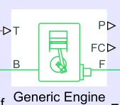
This block represents a system-level model of spark-ignition and diesel engines suitable for use at initial stages of modeling when only the basic parameters are available. There is a mechanical rotational reference connected to a generic engine in order to create the function of function.
The throttle input signal T lies between zero and one and specifies the torque demanded from the engine as a fraction of the maximum possible torque.Connections F and B are mechanical rotational conserving ports associated with the engine crankshaft and engine block.Connections P and FC are physical signal output ports through which engine power and fuel consumption rate are obtained.
Engine Specifications:
In this model we have specified the initial inertia of 1kgm^2 and initial velocity of 2100 rpm.
Engine RPM sensor:
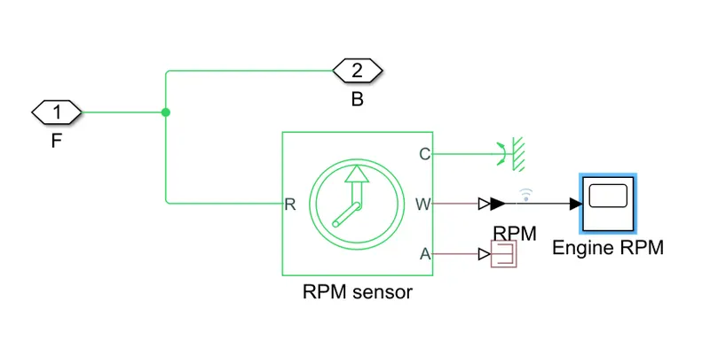
This block represents an ideal rotational motion sensor, this sensor converts a cross variable measured between two mechanical rotational nodes into a control signal proportional to angular velocity or angle. This sensor is ideal since it does not account for inertia,friction,delay,energy consumption.
Connections R and C are mechanical rotational conserving ports and connections W and A are physical signal signal output ports for velocity and angular displacement
CVT:
Image:
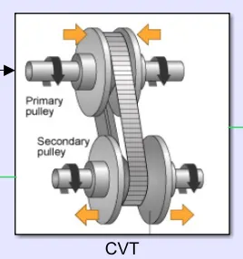
Here the two inertia blocks represent the primary pulley and output shaft inertia represents the secondary pulley inertia.
The variable gear ratio block is used for the model:
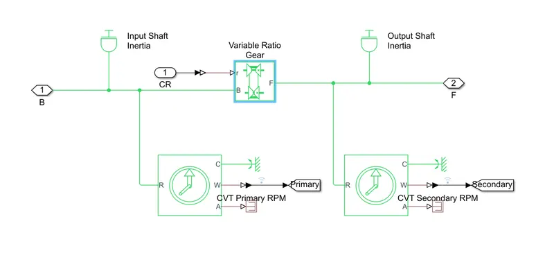
Represents a variable ratio gearbox such as implemented by mechanical belt CVT, electric, or hydraulic transmissions. The physical signal input r defines the ratio of input to output angular shaft velocities.
Connections B (base) and F (follower) are mechanical rotational conserving ports. Specify the relation between base and follower rotation directions with the Output shaft rotates parameter.
Here in the CVT system there are two blocks known as CVT primary RPM sensor and secondary RPM sensor which are basically an ideal rotational motion sensor, they denote the rpm of the driver shaft to the driven shaft.
By these two sensors there can be an instant ratio can be set up to a look-up table or connect it directly to CVT ratio configurator.
Simple Gear:
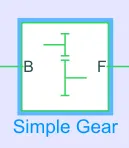
In this system simple gear is implemented because the power has to be transmitted from the output shaft of CVT transmission to the vehicle body. This block represents a fixed-ratio gear. Connections B (base) and F (follower) are mechanical rotational conserving ports. We can optionally add the meshing losses and viscous losses and fix the desired gear ratio.
Vehicle body: In this simscape model the vehicle body is framed by the below image. In which tires are included.
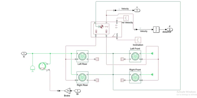
Block diagram for Vehicle body:
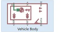
Represents a two-axle vehicle body in longitudinal motion. The block accounts for body mass, aerodynamic drag, road incline, and weight distribution between axles due to acceleration and road profile. The vehicle can have the same or a different number of wheels on each axle.
Connection H is the mechanical translational conserving port associated with the horizontal motion of the vehicle body. The resulting traction motion developed by tires should be connected to this port. Connections V, NF, and NR are physical signal output ports for vehicle velocity and front and rear normal wheel forces.
Here the body is connected to the wheels and the hub of the wheels according to the connections to simulate the working of the body. Here we can include the mass and carry out different simulations for the torque and velocity depending on mass given.Connections W and beta are physical signal input ports corresponding to headwind speed and road inclination angle.
Tire(Magic Formula):
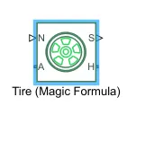
Represents the longitudinal behavior of a highway tire characterized by the tire Magic Formula. The block is built from Tire-Road Interaction (Magic Formula) and Simscape Foundation Library Wheel and Axle blocks. Optionally, the effects of tire inertia, stiffness, and damping can be included.
N-Normal Force, S- Slip , A - Axle, H-Hub
These 4 fitting coefficients are important based on their empirical equation. This block can model tyre dynamics under different conditions. When torque is applied to the wheel axle, tires create a motion to the ground in the backward direction of the wheel. This action results in wheel forward or backward motion.
It can only assume the longitudinal motion where camber,turning or lateral motions cannot be calculated.
Double shoe brake:
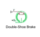
Represents a brake arranged as two pivoted rigid shoes symmetrically installed inside or outside a drum and operated by one actuator. The actuator force causes the shoes to exert a friction torque on a shaft connected to the drum.
Connection S is a conserving rotational terminal associated with the drum shaft. Connection F is a physical signal port representing the force input to the actuator. Positive force creates friction torque that resists shaft rotation.
OUTPUT FOR BAJA ATV MODEL:
In the below output velocity,distance,throttle,brake responses are shown.
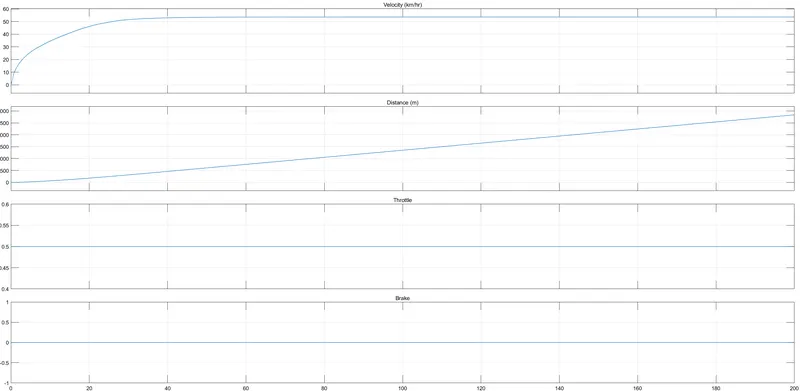
In the below output CVT input shaft vs output shaft is shown.
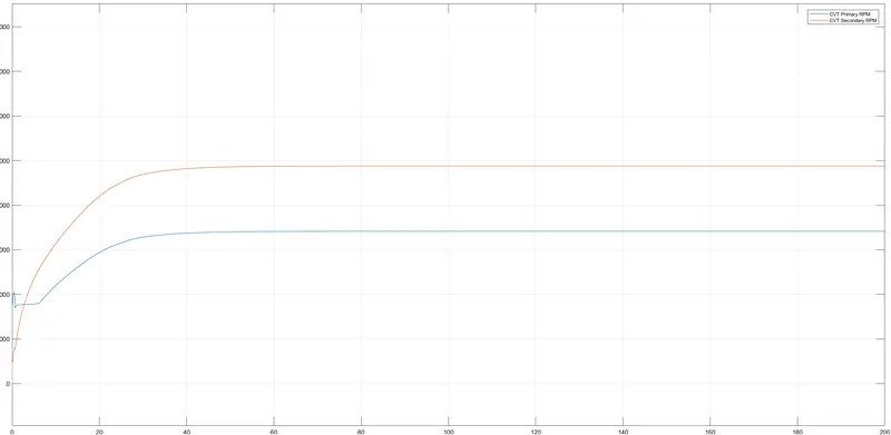
In the below graph Engine RPM is obtained:
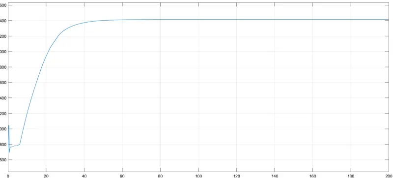
Simscape model of an ATV with mapped dashboard:
OUTPUT:
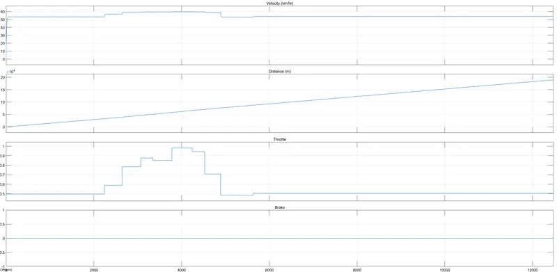
In the below output velocity,distance,throttle,brake responses are shown.
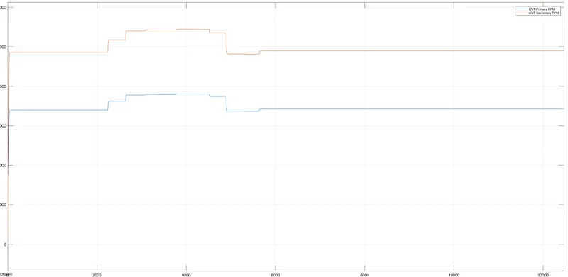
In the below output CVT input shaft vs output shaft is shown.
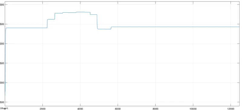
In the below graph Engine RPM is obtained:
Simscape model of an ATV with mapped CVT RATIO RPM:
OUTPUT:
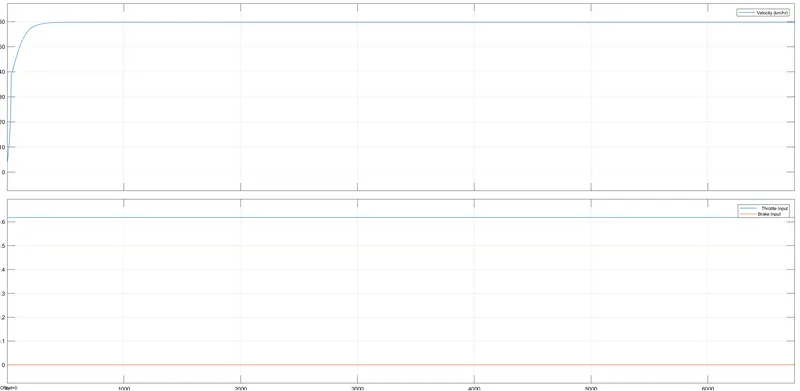
In the below output velocity,throttle,brake responses are shown.
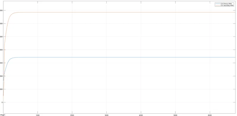
In the below output CVT input shaft vs output shaft is shown.
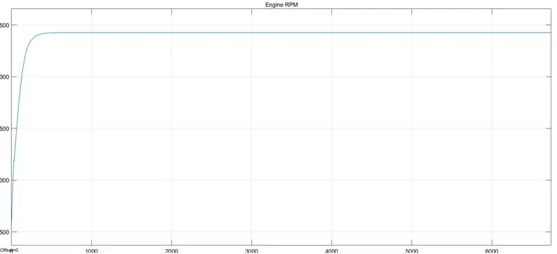
In the below graph Engine RPM is obtained:
In the below graph CVT Ratio has been obtained:

Simscape model of an ATV with mapped VELOCITY OF VEHICLE:
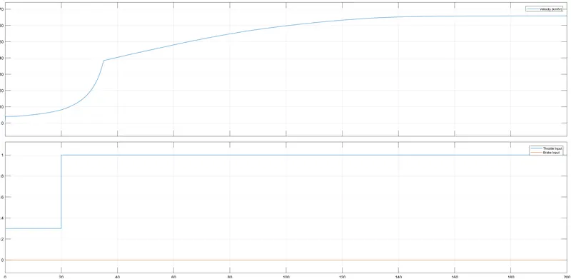
OUTPUT:
In the below output velocity,throttle,brake responses are shown.
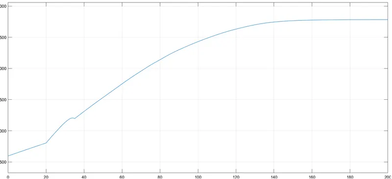
In the below output CVT input shaft vs output shaft is shown.
In the below graph Engine RPM is obtained:
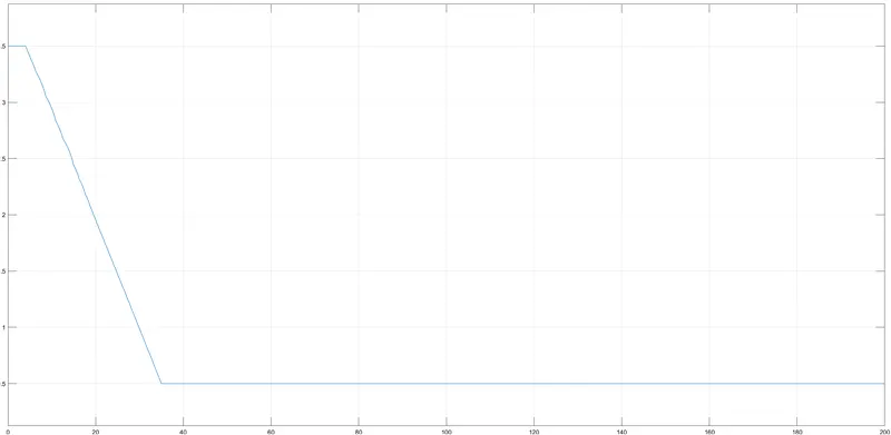
In the below graph CVT Ratio has been obtained:
CONCLUSION:
By the obtained outputs it has been cleared that CVT operations are carried out with 4 different ways in order to identify the best possible of efficiency and power are obtained. Based on this we can clearly say that the secondary CVT pulley has better rpm in all scenarios.