Stateflow for Washing Machine and Gear Shifting
Aim:
- To create a simulink model of washing machine using Stateflow as per squeence provided.
- To create a Simulink chart for the “Gear shift” logic as per conditions provided.
1. Washing Machine:
Conditions:
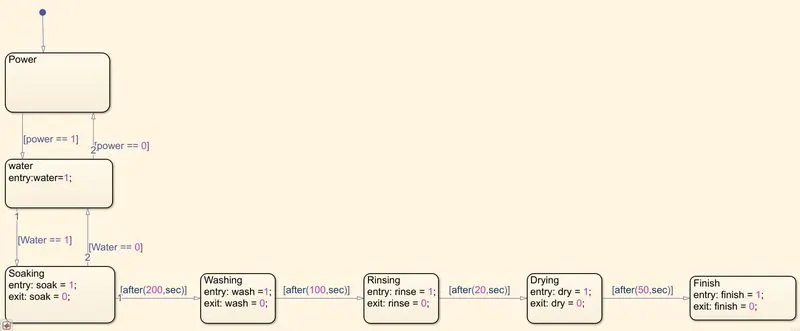
- When the power supply is available, the system gets activated.
- When the Water supply is not available, stop the process & indicate through LED.
- Soaking time should be 200s followed by Washing time of 100s.
- Then rinsing happens for next 20s & dryer runs for 50s.
Model:
Stateflow:
Explanation:
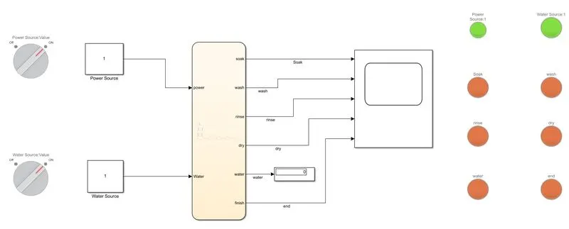
. ON/OFF Switch for turning on the power and water source is connected to a constant value as shown in the model.
. The source is connected to the state flow chart where the given conditons are set as shown in the above state flow.
. The ports are assigned if they are input or output data.
. The ports are connected to a scope to plot the process.
. Lamps indicate the current process as per the run time.
States:
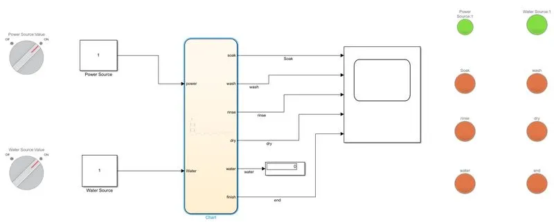
i. Power and Water source ON:
ii. Soaking:
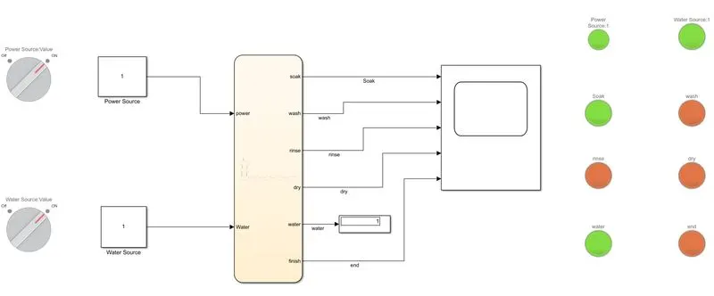
iii. Washing:
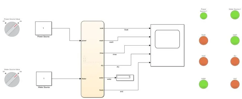
iv. Rinsing:
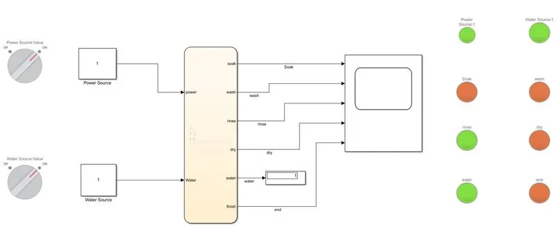
v. Drying:
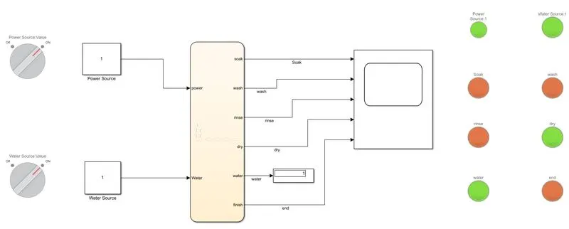
Plot:
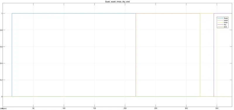
The above plot shows the cycle of washing machine as per the given conditions.
2. Gear Shift:
Conditions:
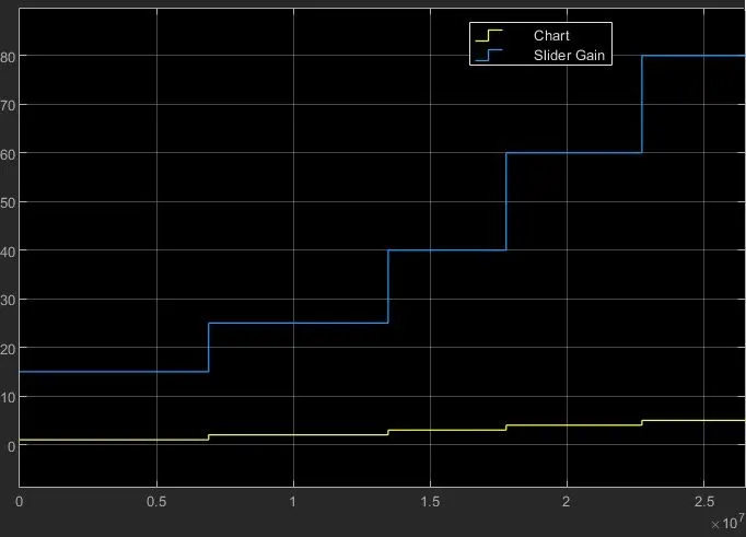
Speed Range(kmph) Gear
0 to 15 1
16 to 25 2
26 to 40 3
41 to 60 4
Above 61 5
Model:
Stateflow:

Explanation:
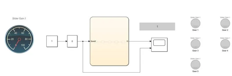
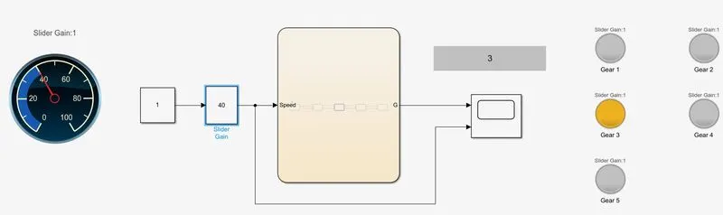
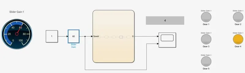
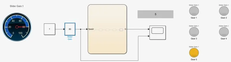
. A slider block is used to vary the speed for transmission and a constant block is required as an input for the slider block.
. The Slider block is connected to the chart in which the conditions are set as shown in the above stateflow.
. The output port is connected to a scope to plot the graph and the output from the slider gain is connected to the same.
. The Speedometer and lamps are connected to the slider gain to indicate the gear and speed.
Output:
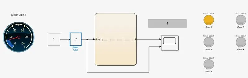
i. First Gear:
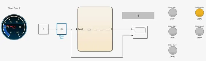
ii. Second Gear:
iii. Third Gear:
iv:
v. Fifth Gear:
Speed and Gear: