Week - 4
1.Implement control logic of a “washing machine” using Stateflow as per given sequence:
- If the power supply is available, the system gets activated
- If the Water supply is not available, stop the process & indicate through LED
- Soaking time should be 200s followed by Washing time of 100s.
- Then rinsing happens for next 20s & dryer runs for 50s
After all the processes have completed turn on the finished LED
Solution:
- If the power supply is available, the system gets activated
- If the Water supply is not available, stop the process & indicate through LED
- Soaking time should be 200s followed by Washing time of 100s.
- Then rinsing happens for next 20s & dryer runs for 50s
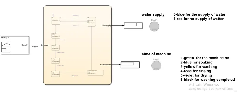
The simulink blocks used in the model are
- Signal builder
- Chart
- lamp
- Display
In order to achieve the condition ,the power and water supply designed the signal from the signal builder for both current and water is made a same signal, for some times the power and water is given and for some times the signal is stopped, it is designed in order to observe the fluctuation of led light.When the power and water is given the chart which is considered the washing machine .By using the control logics and condition ,the machine follows the logic like soaking for 200s, washing for 100s, rinsing for 20s, and drying for 50s. After following the soaking state ,washing state ,rinsing state,drying state,then it goes to the washing completed state.In this way the washing machine checks for the availability of water,electricity and proceeds the state also indicates the state of the machine through the lamp.
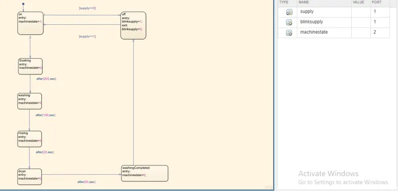
In this chart there are many states and transition they are :
- Default transition
- On,off state
- Soaking state
- Washing state
- Rinsing state
- Drying state
- Completed state
DEFAULT TRANSITION:
- The default transition comes with the first state when using in the chart
- The default transition gets the input from the signal builder
ON ,OFF STATES:
- When the control enters from the default transition goes to the on state and performs the entry action and checks condition for off state if satisfied goes to it ,if not checks the other condition.
- The same applies for the off state ,it does the entry action and continuously checks the supply signal.
- when returning to the on state is does the exit action
SOAKING STATE:
- If the off state condition is not satisfied then it goes to the soaking state.
- When is comes for the soaking state then it does the entry action and takes the delay of 200s and goes to washing state
WASHING STATE:
- After getting enter to the washing state it does the entry action and leaves the washing state
- When leaving the washing state the transition is delayed by the 100s and goes to the rinsing state
RINSING STATE:
- After getting enter to the rinsing state it does the entry action and leaves the rinsing state
- When leaving the rinsing state the transition is delayed by the 20s and goes to the drying state
DRYING STATE:
- After getting enter to the drying state it does the entry action and leaves the drying state
- When leaving the drying state the transition is delayed by the 50s and goes to the completed state
COMPLETED STATE:
- After getting enter to the completed state it does the entry action and leaves the completed state
- When leaving the completed state ,it is directly transmitted to the off state
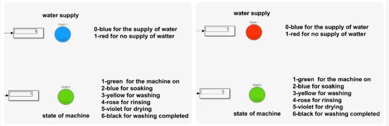
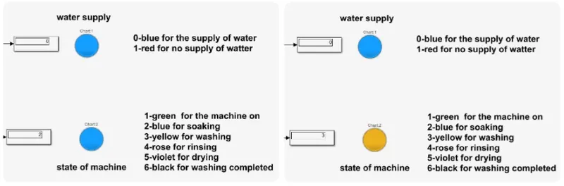
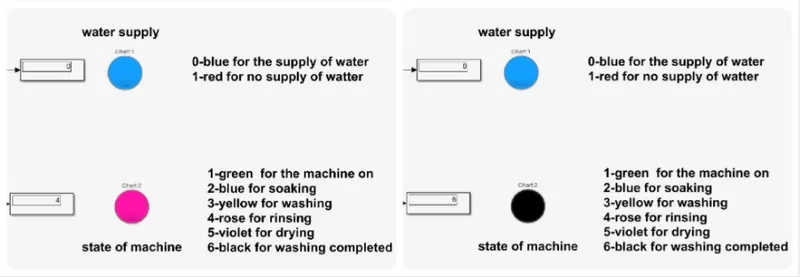
RESULT:
After performing various calculations the simulink model is submitted to give the accurate result.
Thus the control logic of the washing machine using the state flow is performed.
_______________________________________________________________________________________________
2.Make a Simulink chart for the “Gear shift” logic as per below conditions:
Speed Range(kmph) Gear
- 0 to 15 1
- 16 to 25 2
- 26 to 40 3
- 41 to 60 4
- Above 61 5
Give speed input while the simulation is running & display the gear number.
Solution:
To achieve the condition for the speed and gear given below
- 0 to 15 1
- 16 to 25 2
- 26 to 40 3
- 41 to 60 4
- Above 61 5
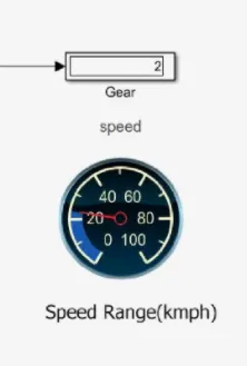
The slider gain is used for the purpose for changing the speed, at the time of running the simulation ,the supply from the slider gain is given to the state flow chart .The state flow chart is is working control logic of the speed and gearshift.It consists of the 6 different states and numbers of transition logic is used to achieve the required results. Also the state action is displayed as the gear in the display block . The custom gauge is used to indicate the speed given to the state flow chart so the custom gauge is connected to the slider gain.
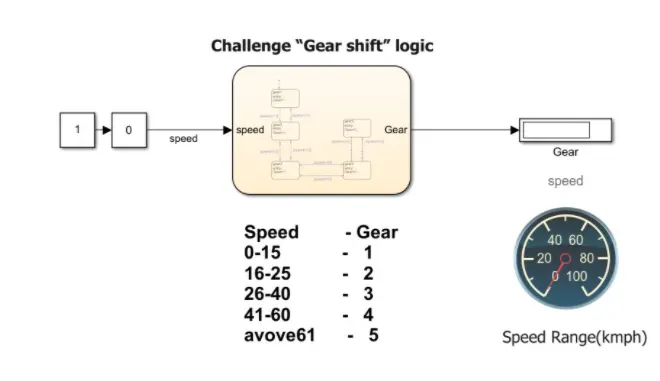
The simulink blocks used in the model are
- constant
- Slider gain
- State flow chart
- Display
- Custom gauge
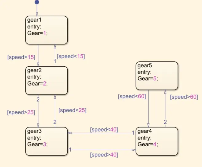
In this chart there are many states and transition they are :
- Default transition
- Gear 1
- Gear 2
- Gear 3
- Gear 4
- Gear 5
DEFAULT TRANSITION:
- The default transition comes with the first state when using in the chart
- The default transition gets the input from the signal builder
GEAR 1
- The default transition gets into the gear1 state first, and then does the entry action .
- The entry action gives the gear number as output to the display.
- It remains in the state till the condition is satisfied.
- While leaving the state it has to satisfy the necessary condition for the transition.(speed>15)
GEAR 2:
- There are 2 possibilities of reaching the state one is from state gear1 and other is from state gear2 .
- After entering the state it does the state action.
- The entry action gives the gear number as output to the display.
- It remains in the state till the condition is satisfied.
- While leaving the state it has to satisfy the necessary condition for the transition for either state gear1 or gear3.(speed <15 or Speed >25)
GEAR 3:
- There are 2 possibilities of reaching the state one is from state gear2 and other is from state gear4 .
- After entering the state it does the state action.
- The entry action gives the gear number as output to the display.
- It remains in the state till the condition is satisfied.
- While leaving the state it has to satisfy the necessary condition for the transition for either state gear4 or gear2.(speed <25 or Speed >40)
GEAR 4:
- There are 2 possibilities of reaching the state one is from state gear3 and other is from state gear5 .
- After entering the state it does the state action.
- The entry action gives the gear number as output to the display.
- It remains in the state till the condition is satisfied.
- While leaving the state it has to satisfy the necessary condition for the transition for either state gear5 or gear3.(speed <40 or Speed >60)
GEAR 5:
- There is only 1 possibility of reaching the state that is from state gear4 .
- After entering the state it does the state action.
- The entry action gives the gear number as output to the display.
- It remains in the state till the condition is satisfied.
- While leaving the state it has to satisfy the necessary condition for the transition for state gear4 (speed <60 ).
CUSTOM GAUGE:
- This block is used to indicate the speed given is the input to the state flow.
- This is connected to the slider gain ,so the value given will reflect in the custom gauge.
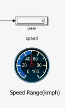
RESULT:
After performing various calculations the simulink model is submitted to give the accurate result.
Thus the Simulink chart for the “Gear shift” logic is made using state flow,and the results are shown below.
_________________________________________________________________________________________________
https://drive.google.com/drive/folders/1h2gm0oX_JVDCu0mzuqCqZKpiMdJGL3GJ?usp=sharing