Washing Machine and Gear Shift Logic
Aim:- Implement Control Logic of a 'Washing Machine' using Stateflow as per given sequence.
Objective:- As per given sequence
- If the power supply is available, the system gets activated
- If the Water supply is not available, stop the process & indicate through LED
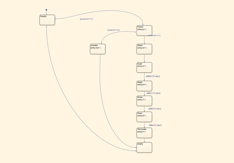
- Soaking time should be 200s followed by Washing time of 100s.
- Then rinsing happens for next 20s & dryer runs for 50s
After all the processes have completed turn on the finished LED.
Theory:-
Stateflow:- Stateflow provides a graphical language that includes state transition diagrams, flow charts, state transition tables and truth tables. Stateflow can be used to describe how MATLAB algorithms and Simulink models react to input signals, ebents and time based conditions.
Stateflow enables you to design and develop supervisory control, task scheduling, fault management, communication protocols, user interfaces, and hybrid systems.
State Machine:- A finite state machine is a representation of an event-driven (reactive) system. In an event-driven system, the system responds to an event by making a transition from one state (mode) to another. This transition occurs if the condition defining the change is true.
Chart:- A Stateflow Chart is a graphical representation of a finite state machine. These charts can be used to control a physical plant in response to events such as a temperature and pressure sensor, clocks and user driven events.
Control Logic used in "Washing Machine"
Procedure:-
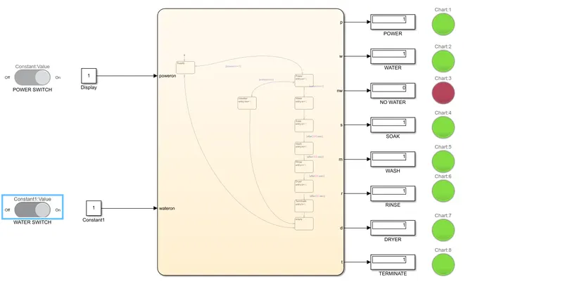
In this i have made the charts in which logics are provided to it which make it to take those logics and run it accordingly. These charts are thereafter connected to some inputs and through this some outputs are produced which is used to run the simulation.
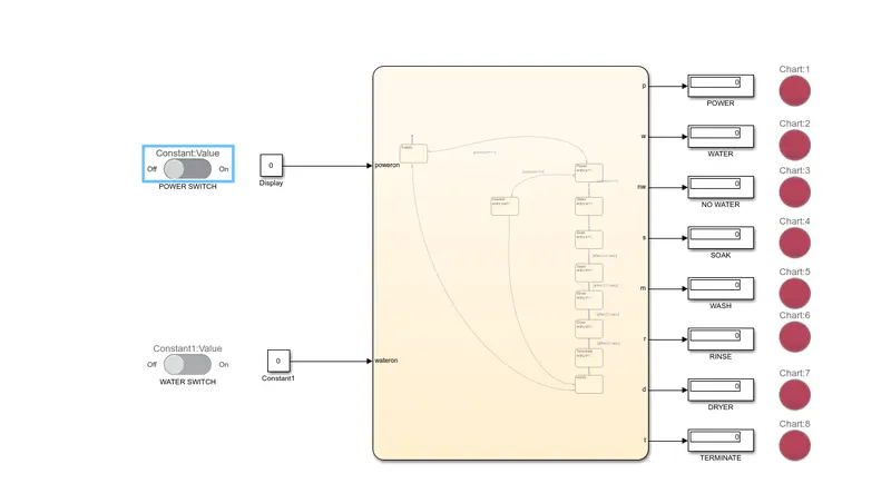
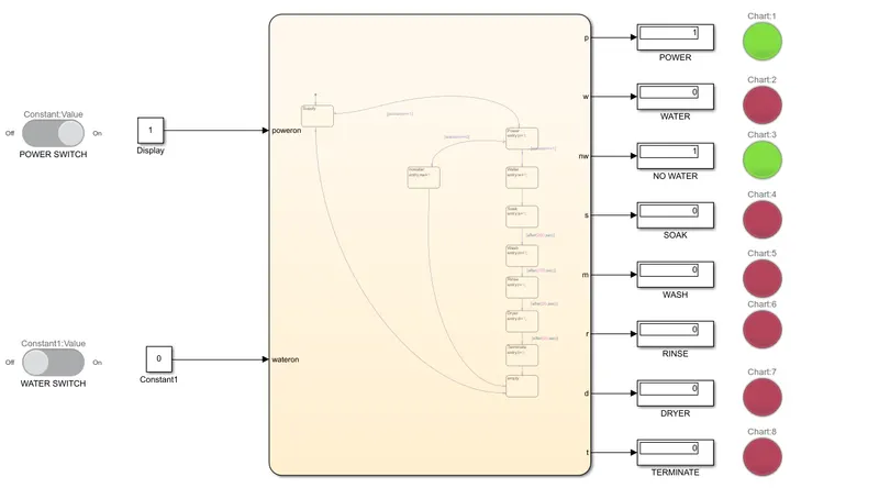
Display is connected to every output source which shows the value of that particular connection and each of these are too connected with the lightning lamp that indicate the value either the running condition is true or false. If the value displayed is 1, lamp will light green i.e. the condition is true and the further process will takes place. If the value displayed is 0, lamp will light red i.e. the condition is false and the further process wont take place as it tends to stop there.
Power Supply is given to them as poweron==1 which means power is on and is suppplied to do the other works and if poweron==0 means no power and its sent to empty block.
At the entry of Power one link is connected with the no water block which indicate no water in the tub and send to the empty block.
The blocks are connected through links and applied logics to it which can provide proper output.
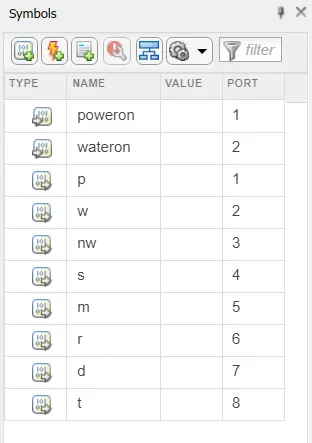
Simulink Model for Washing Machine
1) When Power Supply and Water Supply are OFF.
2) When Power Supply is ON and Water Supply is OFF.
3) When Power Supply and Water Supply are ON.
Aim:- Make a Simulink chart for the “Gear shift” logic.
Objective:- as per below conditions:
Speed Range(kmph) Gear
0 to 15 1
16 to 25 2
26 to 40 3
41 to 60 4
Above 61 5
Give speed input while the simulation is running & display the gear number.
Theory:-
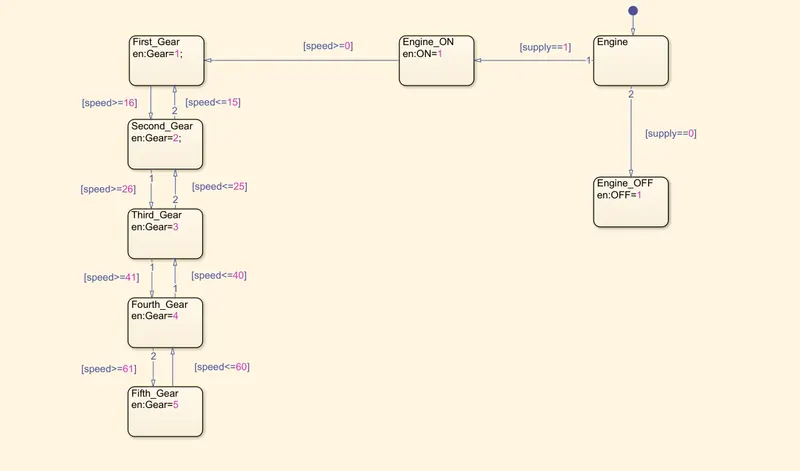
Control Logic for "Gear Shift" in car.
Procedure:-
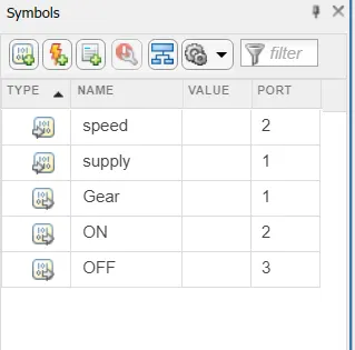
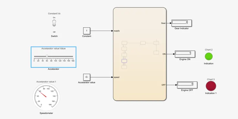
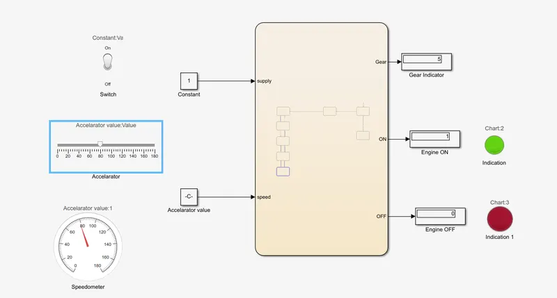
First i have taken chart block and into this control logic is provided which shows the proper working of the gear shifting. Engine block shows the teo conditions i.e. if [supply==1] it means Engine is ON and is in running condition and if [supply==0] it means Engine is OFF.
If the [speed>0] condition given that means the gear shifted in first and start moving the vehicle from speed 0 to 15kmpl and if speed reduces below 15 the vehicle will automatically reduces to 1st gear from 2nd and this thing goes on continuously for different gears too. This block is followed by the engine ON block. Afterall each and every block of gear shift is followed in the same category.
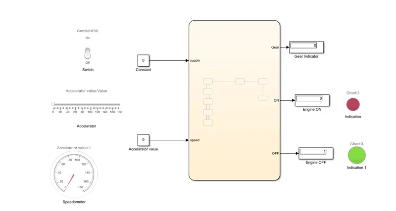
So the speed and supply are given inputs and the Gear, Engine ON, Engine OFF, conditions are provided output. Through the output a display block is attached to gear which shows the gear indication and to the ON/OFF to show their conditions. Lamp is connected with them so that it can indicate easily whether an engine is in ON/OFF state.
At the input ports Switch is given which shows whether an engine is switched ON/OFF. Slider Gauge is provided in this which acts as an Accelarator Pedal to increase the speed of vehicle and shows the indication of gear shipt simultaneously. Gauge block is provided which acts as an Speedometer, is also attached with that so that we can see in which speed the car is moving.
Conditions:-
1) When Switch is OFF.
2) When Switch is ON.
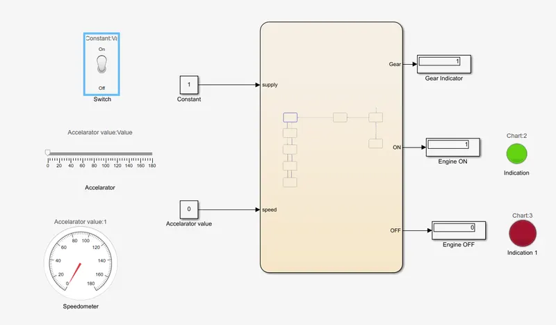
3) When Speed is 0 - 15 kmpl.
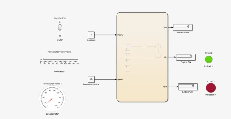
4) When Speed is 16 - 25 kmpl.
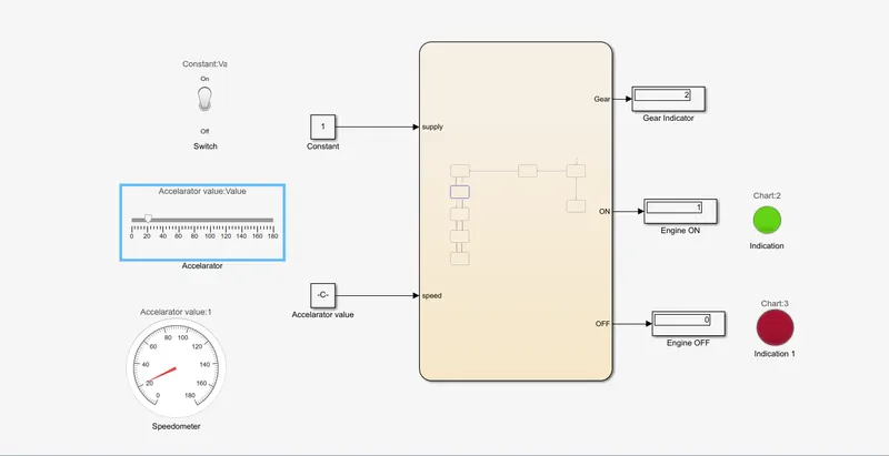
5) When Speed is 26 - 40 kmpl.
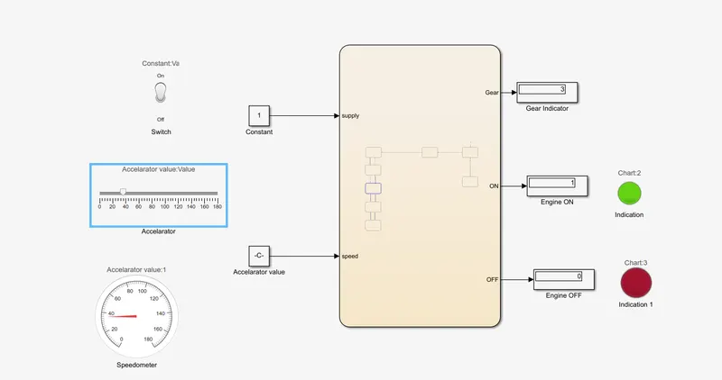
6) When Speed is 41 - 60 kmpl.
7) When Speed is above 61 kmpl.
Learning Outcome:-
Learn about Stateflow, Charts, Control Logic, State machine.
Learn how to make control logic of Washing Machine.
Learn how to make control logic of Gear Shift.