Simulink model of Door bell
Aim:- Make a simulink model of doorbell using solenoid block with the following details:
In the above arrangement, when the switch is closed the electromagnet receives electrical power from the battery and pulls the metal arm to hit the bell producing sound.
Create a situation where the switch is closed for 2 seconds and then released. Observe the physical movement of the plunger.
Theory:-
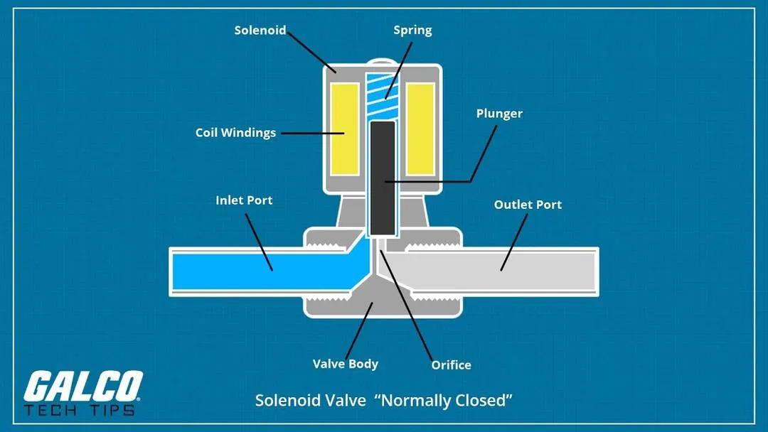
Solenoid:- A Solenoid is a device comprised of a coil of wire, the housing and a movable plunger(armature). Whenever an electric current is introduced a magnetic field forms around the coil which draws the plunger in. A Solenoid is a type of electromagnet that converts electrical energy to mechanical work.
Image of Solenoid Valve:-
Blocks used:-
1) Scope
2) Simulink-PS convertor
3) Battery
4) Electrical Reference
5) PS-Simulink Convertor
6) Solenoid
7) Solver Configuration
The above blocks were explained earlier but the remaining main blocks which are used into this are:-
Pulse generator:-
The Pulse Generator block generates square wave pulses at regular intervals. The block waveform parameters, Amplitude, Pulse Width, Period, and Phase delay, determine the shape of the output waveform.
Ideal Translational Motion Sensor:-
The Ideal Translational Motion Sensor block represents a device that converts an across variable measured between two mechanical translational nodes into a control signal proportional to velocity or position. You can specify the initial position (offset) as a block parameter.
Mechanical Translational Reference:-
The Mechanical Translational Reference block represents a reference point, or frame, for all mechanical translational ports. All translational ports that are rigidly clamped to the frame (ground) must be connected to a Mechanical Translational Reference block.
SPST Switch:-
The SPST Switch block models a single-pole single-throw switch:
-
When the switch is open, port p is connected to port n through a resistance with value equal to the reciprocal of the Open conductance parameter value.
-
When the switch is closed, port p is connected to port n through a resistance with value equal to the Closed resistance parameter value.
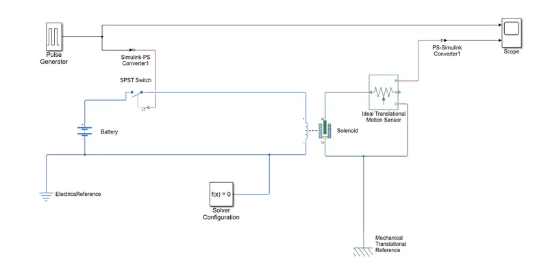
Block Diagram of Simulink:-
Procedure:-
1) Pulse generator generates square wave pulses at regular intervals. Its first created to sense the puse and is carry forward to the switch. The another part of this is connected to the scope.
2) The SPST Switch is connected to the battery terminals which is further connected to the Solenoid.
3) Solenoid is connected to the Ideal Translational motion sensor through the input and two output ports are connected i.e. one to scope and another to the terminal of solenoid which creates a closed loop.
4) Initial Position of Solenoid plunger is given 5mm. When the solenoid is active the rod position actives and comes to zero position and hits the bell.
5) the vibration of large amplitudes after hitting bell and reaching its initial position are reduced by adjusting the damping coefficient of the solenoid.
Output:-
Graph showing the signals
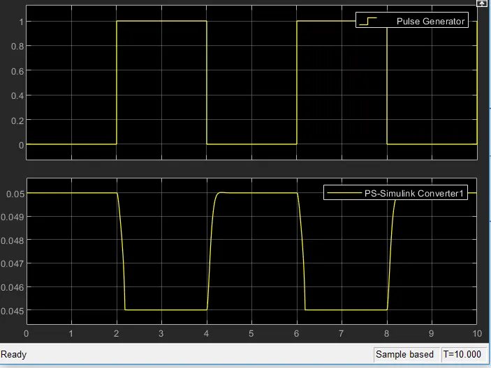
Initially the graph is at '0' position. When solenoid plunger gets active it goes upward and stay there for 2 seconds and then come to rest as if circuit is switched off.
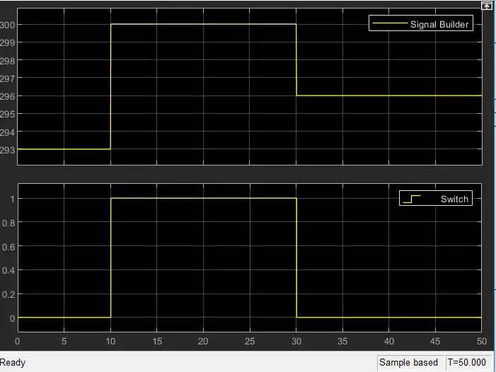
Aim:- Use a thermistor to sense the temperature of a heater and turn or turn off the fan as per below conditions:-
Temperature source: 20 °C from 0 to 10 seconds, 27 °C from 10 to 30 seconds, 23 °C from 30 to 50 seconds
Fan conditions: ON if the temperature above 25 °C, OFF otherwise
Theory:-
Main blocks used:-
1) Signal Builder block:-
This signal builder block is used to generate the signal according to the inputs provided. This could be used to build signals on own.
2) Controlled Temperature Source:-
The controlled temperature source block represents an ideal source of thermal energy that is powerful enough to maintain specified temperature difference across the source regardless of the heat flow consumed by the system.
3) Thermistor:-
A thermistor is a resistance thermometer or a type of resistor whose resistance is strongly dependent on temperature. The term is combination of thermal and resistor. It is made of metallic oxides, pressed into a bead, disk, or cylindrical shape and then encapsulated with an impermeable material such as epoxy or glass.
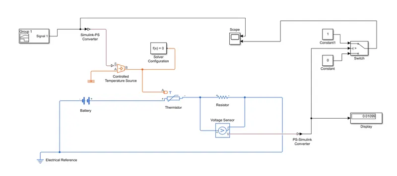
Block diagram of Heater and Fan:-
Procedure:-
1) First i build the signals from the signal builder and provide the inputs as per given criteria.
2) Now the signals are passed from Simulink-PS Convertor to the Controlled Temperature Source where these are further connected to the thermistor.
3) Thermistor are ahead connected to the battery terminals and to the resistor which is attached to the Voltage sensor.
4) Voltage sensor is provided to sense the voltage of current which is placed across the resistor.
5) A threshold value of voltage is provided corresponding to the temperature 25 degree celsius. If the value is above that the current flows through it and graphs are produced.
6) If a value is greater then threshold value it shows '1' otherwise '0'.
Output:-
Graph showing the signals builder
Learning Outcomes:-
1) I was able to make the model of dooe bell using Solenoid block.
2) I was able to make a block on thermistor to sense the temperature of a heater and turn on or turn off the fan.
3) This task helped me a lot in understanding the blocks and working of it.