Week - 4
AIM:
To implement control logic of a "washing machine" using stateflow as per given sequence
OBJECTIVE:
- If the power supply is available, the system gets activated
- If the water supply is not available, stop the process and indicate through LED
- Soaking time should be 200s followed by washing time of 100s
- Then rinsing happens for the next 20s and dryer runs for next 50s.
After all the process completed we have to turn ON the finished LED
STATEFLOW:
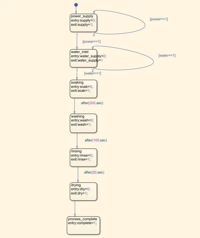
- State flow starts with the power supply state and the logic is that if power input is 1
- If the power supply is 0 (where no power supply)and a lamp can be used to indicate
- State flow chart of washing machine is used as inputs to be provided for the washing machine.
- The following process of washing machine are giving power more then water comes in where soaking starts with a given period of time 200secs.
- The washing in period of 100secs follows rinsing and drying of 20s and 50s before machine stops running.
- The fibnal state consist of a value of 1 at the entry and it allows for indicating the cycle completion lamp.
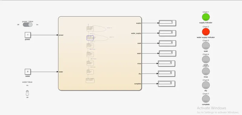
- where in the above simulation power supply is given ON
- So the LED indicates the green colour
- The water supply is not given so the LED so it is indicated in red which shows the error supplying of water.
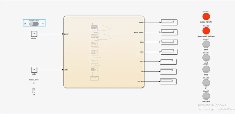
- This is the initial simiulation of washing machine before giving power and water supply
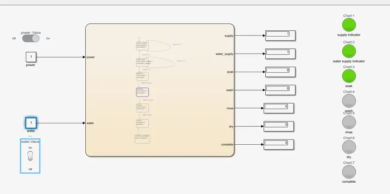
- Where the above simulation shows the working of model
- Where the power water is ON so the soaking process starts with the time period of 200secs which the soak LED indicated of soak process undergoes.
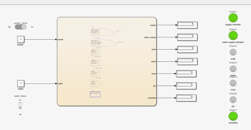
- The above simulation shows the completion of process involved in washing machine with the LED indication
GEAR SHIFT:
AIM:
To make a similink chart for the GEAR SHIFT logic as per the conditions.
OBJECTIVE:
Speed range (kmph) GEAR
0-15 1
16-25 2
26-40 3
41-60 4
Above 61 5
Give the speed input chart while the simulation is running and display the gear number
FLOW CHART:
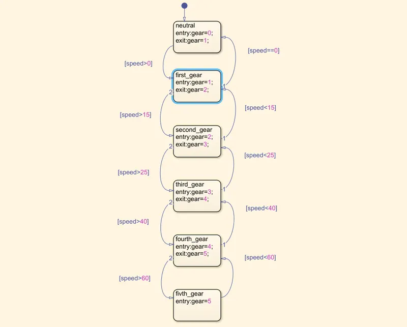
- State flow chart is used as the inputs to be provided for the gear shift simulation. where the command work on the speed range given for each block.
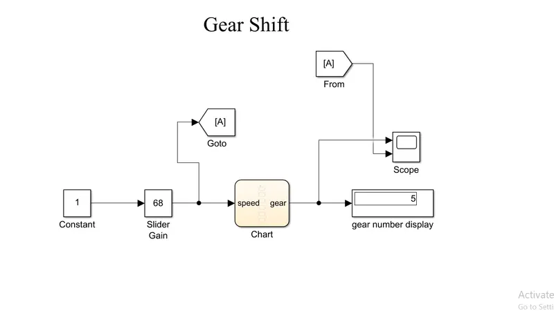
- Simscape model for gear shift .
- The blocks used are slider gain, chart, display, scope and gear.
- The slider gain is used to acclerating or deacclerating the vehicle with given values for a limit of low to high.
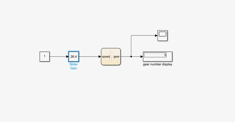
- where accleration is given as 26.4 in slider gain the output shows the 3 which is the vehicle running in 3rd gear at a accleration of 26.4.
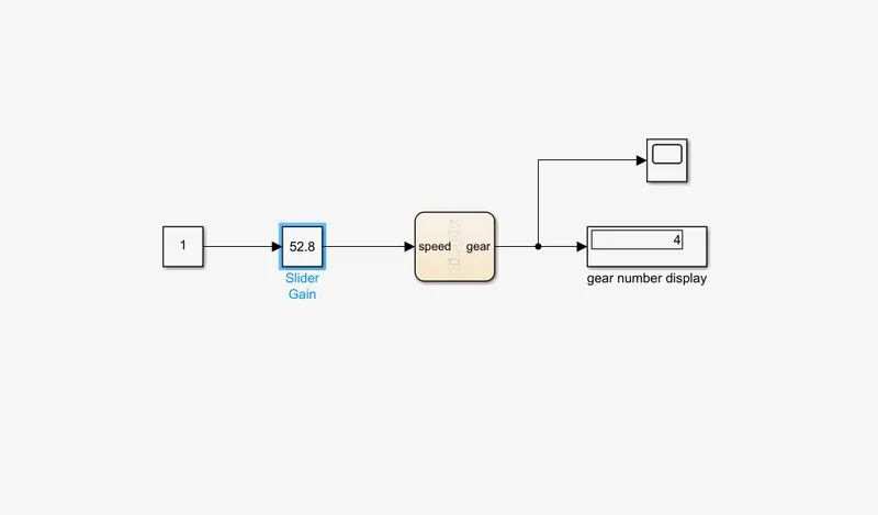
- where the accleration is given as 52.8 in slider gain the output shows 4 whih the vehicle is running in 4th gear at a accleration of 52.8.
GRAPH:
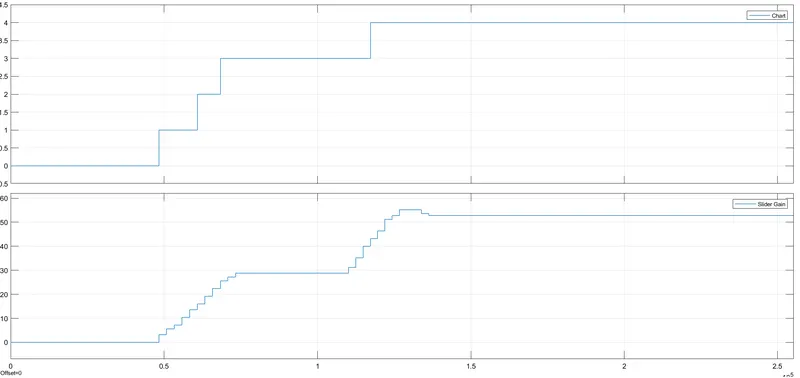
- The top plot shows the gear position indicator and the bottom plot denotes the speed input with respective time.
RESULT:
The control logic for washing machine and simulink chart for gear shif is moulded.