Week -2
AIM:
- To make a Simulink model of doorbell using the solenoid block.
OBJECTIVES:
- The model of doorbell is using the solenoid block, that we have to create a situation where the switch is closed for 2 seconds and then released and observe the position of the plunger.
THEORY:
Solenoid:
- A solenoid is a type of electromagnet, the purpose is to generate a controlled magnetic field through a coil wound into a tightly packed helix
- The coil can be arranged to produce a uniform magnetic field in a volume of space when an electric current is passed through it.
- In the study of electromagnetism, a solenoid is a coil whose length is substantially greater than its diameter.
In engineering, the term may also refer to a variety of transducer devices that convert energy into linear motion. The term is also often used to refer to a solenoid valve, an integrated device containing an electromechanical solenoid which actuates either a pneumatic or hydraulic valve, or a solenoid switch, which is a specific type of relay that internally uses an electromechanical solenoid to operate an electrical switch; for example, an automobile starter solenoid or linear solenoid. Solenoid bolts, a type of electromechanical locking mechanism, also exist. In electromagnetic technology, a solenoid is an actuator assembly with a sliding ferromagnetic plunger inside the coil. Without power, the plunger extends for part of its length outside the coil; applying power pulls the plunger into the coil. Electromagnets with fixed cores are not considered solenoids.
- The basic components used to set up a simple doorbell circuit are:
- Battery
- Switch
- Solenoid
- A bell with a plunger
MODEL:
WORKING:
Explanation:
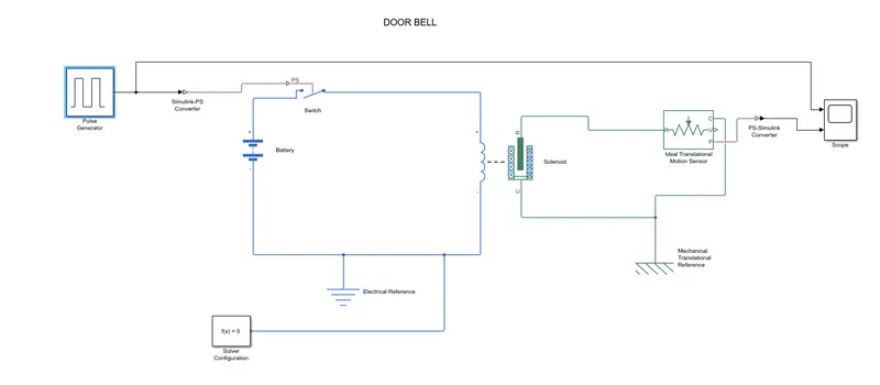
- From the above governing circuit of a doorbell, we know that we need a switch, battery and plunger.
- So, in order to get all these components in Simulink model we have to take the blocks which perform the same function as the above devices perform.
- Now first a ‘Solenoid block’ is taken to represent a solenoid in the model, then we take a ‘Battery block’ from the library browser.
- Then this ‘Solenoid block’ and ‘Battery block’ is connected through the positive and negative terminals.
- A ‘Switch block’ is used between the ‘Solenoid block’ and ‘Battery block’.
- Now for the switch to operate we must provide a physical signal through ‘PS’ port in the ‘Switch block’.
- The provided physical signal must be greater than the threshold of the switch, for the switch to be closed or else it will be opened.
- Now this whole battery, switch and solenoid path is connected to ‘Electrical Reference block’ which represents the earthing of the circuit.
- The ‘Electrical Reference block’ should be connected with the negative terminal of the ‘Battery block’
- Now we provide a physical signal for operating the switch we have used the ‘Pulse Generator block’ which generates a continuous square pulse
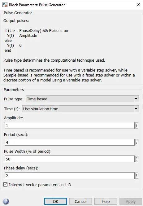
- From the above Figure we can observe that we have given period value as ‘4’, pulse width as ‘50’, phase delay as ‘2’ and amplitude by default is ‘1’ we have not changed it. This means that initially the pulse will be zero and at 2 secs the pulse width will half of periods
- so for the next two seconds the pulse will be at amplitude ’1’ only, then it will again come down to zero at 4thsecond and then it will at zero for next 2 secs thus completing the periods of 4 seconds.
- To this ‘Pulse Generator block’ a ‘Scope block’ is connected to see how the pulse is generated
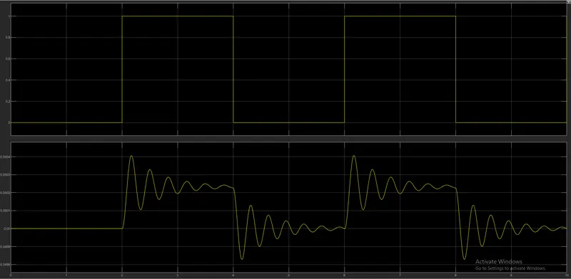
- As mentioned before, the pulse has started after 2 seconds, then for next two seconds it has amplitude of ‘1’ and then next 2 seconds the pulse is again zero.
- The pulse is starting from 2 seconds and ending at 6 seconds which nothing but a time period of 2 seconds.
- Since the pulse that is coming from ‘Pulse Generator block’ is a Simulink value, so to convert this value into physical value we have used ‘Simulink-PS Converter block’, since switch only takes physical value as inputs
- Now run the model and double click on the ‘Scope block’ which is connected to ‘Ideal Translational Motion Sensor block’ to get the results.
- We will get above graph as the result when we double click on the ‘Scope block’. Here x-axis represents the time in seconds and y-axis represents position of plunger in mm.
- Again, as the amplitude of the pulse becomes zero, the plunger returns to its initial position back again and as the pulse cycle goes on, plunger also changes its position and comes back to its initial position.
- We can also observe that when there is a change in position of the plunger, there are some wave forms at the start of changes in position. This is due to recoil of the spring, each time when the plunger is moving.
- So to reduce this, in the ‘Solenoid block’ we can reduce the spring constant value and increase the damping co-efficient. This will reduce the waves that are being formed and we will get a smooth graph.
RESULT:
CONCLUSION:
Thus, both the objectives were achieved successfully.
STUDY-2: SENSING TEMPERATURE OF A HEATER:
AIM:
- To make a Simulink model using a thermistor to sense the temperature of a heater and turn on and turn off the fan.
OBJECTIVES:
- For the model we must use a thermistor to sense the temperature of the heater and turn on and off the fan as per the below conditions:
- Temperature source:
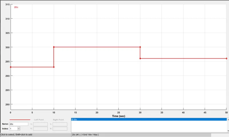
- 20 °C from 0 to 10 seconds.
- 27 °C from 10 seconds to 30 seconds.
- 23 °C from 30 seconds to 50 seconds.
- Fan conditions:
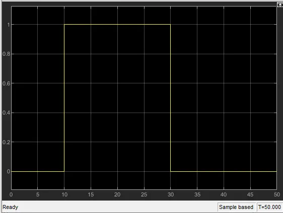
ON if the temperature is above 25 °C, OFF otherwise.
THEORY:
Thermistor:
- A thermistor is a type of resistor whose resistance is dependent on temperature, more so than in standard resistors. The word is a combination of thermal and resistor.
- Thermistors are widely used as inrush current limiters, temperature sensors (negative temperature coefficient or NTC type typically), self-resetting overcurrent protectors, and self-regulating heating elements (positive temperature coefficient or PTC type typically).
Thermistors are of two opposite fundamental types:
- With NTC thermistors, resistance decreases as temperature rises. An NTC is commonly used as a temperature sensor, or in series with a circuit as an inrush current limiter.
- With PTC thermistors, resistance increases as temperature rises. PTC thermistors are commonly installed in series with a circuit, and used to protect against overcurrent conditions, as resettable fuses.
Thermistors differ from resistance temperature detectors (RTDs) in that the material used in a thermistor is generally a ceramic or polymer, while RTDs use pure metals. The temperature response is also different; RTDs are useful over larger temperature ranges, while thermistors typically achieve a greater precision within a limited temperature range, typically −90 °C to 130 °C.
The basic components used to set up a simple cooling fan circuit are:
- Battery
- Thermistor
- Fan
- Transistor
Resistor
MODEL:
WORKING:
Explanation:
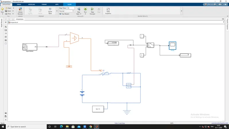
- To create a Simple Cooling Fan model using Thermistor we need a thermistor, battery, resistor, voltmeter, a logical switch which are basic components of the circuit we need in the Simulink model.
- To represent a thermistor, a ‘Thermistor block’ is taken and placed in the model.
- To represent a battery, a ‘Battery block’ is taken and the positive port of this block is connected to positive port of the ‘Thermistor block’.
- Now to represent a resistor, a ‘Resistor block’ is taken from the library browser and its positive port is connected to negative port of the ‘Thermistor block’.
- The negative port of ‘Resistor block’ is connected to the negative port of the ‘Battery block’. Now an ‘Electrical Reference block’ is connected near the negative terminal of the ‘Battery block’ which represents the earthing of the real time circuit.
- Now to represent a voltmeter a ‘Voltage Sensor block’ is connected parallel to the ‘Resistor block’, because to measure to voltage across a component, voltmeter should be always connected parallel to that component.
- In this case we need the fan to get ON and OFF at different temperatures. So, to provide temperature, we have used ‘Controlled Temperature Source block’ which only gives a specified temperature as output even though heat flow is more.
- Now to give different temperatures to this ‘Controlled Temperature Source block’ we need to send temperature signals.
- To send these signals we have used a ‘Signal Builder block’ which allows use to send any type of signals as inputs.
- We have to double click on the ‘Signal Builder block’ to set the signal according to our requirement.
- When we open the ’Signal Builder block’. As this dialogue box opens, first we have to click on the ‘Signal’ at the top and then select ‘New’ ten select ‘Custom’ option. Now it will ask to give values of y-axis and x-axis.
- We can see that how different temperature are given at different time. So, thus we have created our signals and before connecting it to the ‘Controlled Temperature Source block’ we have to convert these signals into a physical value.
- So now the port ‘B’ of ‘Controlled Temperature Source block’ is connected to port ‘A’ of the ‘Thermistor block’ and port ‘A’ of ‘Controlled Temperature Source block’ is connected to the a ‘Thermal Reference block’.
- In ‘Controlled Temperature Source block’ a positive temperature difference causes the temperature at port B to be greater than the temperature at port A.
- Now the output of the ‘Voltage Sensor block’ is connected to ‘Display block’ first, and before connecting to the ‘Display block’ a ‘PS-Simulink Converter’ is used to convert physical values to Simulink values.
- Now when we run the simulation and double click on the ‘Display block’ and we will get the voltage at 25 °C, using this information we can set conditions for fan to ON and OFF.
- As mentioned in the objective fan should be ON when temperature is more than 25 °C, i.e. when the voltage is more than 5.665e-22 then fan should ON and when the voltage is below 5.665e-22 the fan should be OFF.
- The above logic used to ON and OFF the fan. To do this we have used a ‘Switch block’ that routes the signals according to the conditions provided.
- The center port of ‘Switch block’ is connected to the output of ‘PS-Simulink Converter’ which gives the voltage values. The top port of the ‘Switch block’ is connected to a ‘Constant block’ of value 1 and bottom port of the ‘Switch block’ is connected to another ‘Constant block’ of value 0.
- The center port of ‘Switch block’ is the condition input which means that when the value from ‘Voltage Sensor block’ is more than the threshold value in the ‘Switch block’ then it will pass the value 1 which we have specified in the top port of the ‘Switch block’.
- If the voltage from ‘Voltage Sensor block’ is less than the threshold value in the ‘Switch block’. Here it acts like a transistor in a real time circuit.
- To set the threshold value of ‘Switch block’, we have to double click on the ‘Switch block’ and then we can change the value of threshold. Since we want switch to be ON only when temperature is 300K so the threshold is given as 5.665e-22. So when voltage gets more than 5.665e-22 the switch will give value 1 as output which means fan will be ON and when voltage gets less than 5.665e-22 the switch will give value 0 as output which means fan will be off.
Now the output of the ‘Switch block’ is connected to another port to get the results.
RESULT:
CONCLUSION:
- A similar approach can be used for simulating other physical devices using Simulink.