Week 4.1: Project Steady state simulation of flow over a throttle body
Week 4.1: Project Steady State Simulation of Flow over a Throttle body.
Aim:
- The main aim of the project is to simulate a flow over a throttle body in steady state condition.
- To post process the results and show pressure and velocity contours.
- To display the mesh.
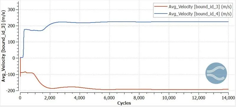
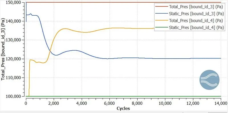
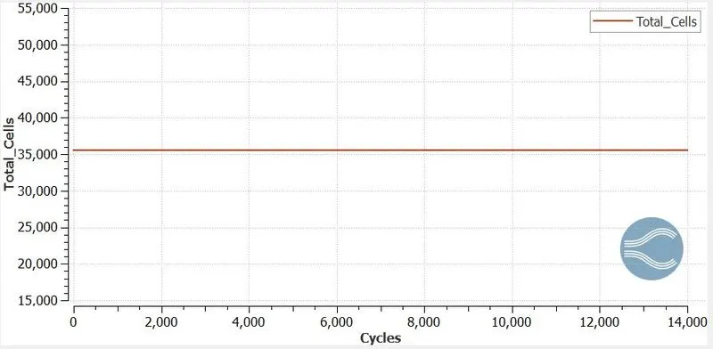
- To display the plots for pressure, velocity, mass flow rate and total cell count.
Introduction:
Throttle Body:
- The amount of air that flows into an engine’s combustion chamber is controlled by throttle body which is a part of the air intake system.
- It consists of housing unit that contains a throttle plate that rotates on a shaft.
- Throttle body is located between the air filter and the intake manifold.
Geometry Setup:
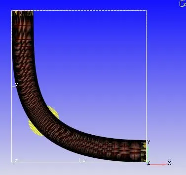
- As the geometry was provided in STL format it is imported in the CONVERGE studio software by using the file--> import --> import STL command.
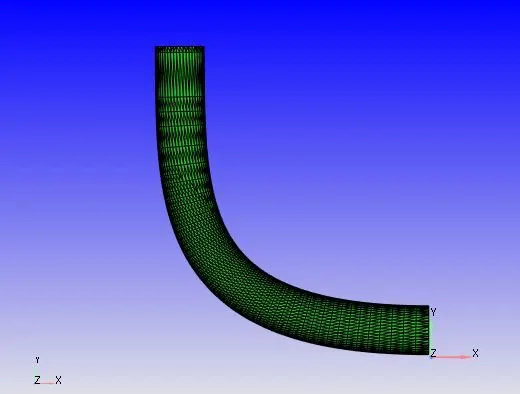
- Diagnosis toolbar is used for geometry check-up.
- The effect of thickness which is responsible for conjugate heat transfer are neglected for this flow over throttle body case.
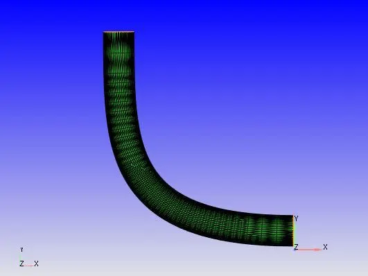
- Then as the geometry as open edges it is closed by using the Geometry dock--> Repair--> Patch--> Free edge loop--> select the open edge and click on apply.
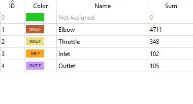
- In the next step the boundaries flag with names.
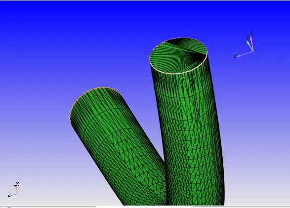
- Then the normal are checked whether they are pointing inside the geometry where does the flow passes.
Case Setup:
- The application type is fixed with time based.
- Then click on Materials which is present in the right side of the window that is case setup tree and select the Predefined mixtures as Air.
- Click on the Gas simulation and Global Transport parameter and retain the same values.
- Click on Species and then add O2 and N2.
- Click on Run Parameters and under the solver tab choose the solver as Steady-State Solver. Set the simulation mode to Full Hydrodynamic and the gas flow solver as compressible.
- Then under "Misc" tab check the Steady-state monitor and uncheck the use shared memory boxes.
- Then coming to Boundary Conditions click on Boundary--> Inlet -->Specify the inlet pressure value as 1.5e5 Pa and select the predefined mixture as Air which contains N2 of 77% and O2 of 23% and then under the Temperature boundary condition choose specified value and allocate the temperature value with 300k.
- Then in Outlet--> Specify the static pressure as 1e5 Pa and select the predefined mixture as Air.
- Then assign the Elbow and Throttle boundary condition as Wall.
- Then under the Simulation Parameter --> Run Parameters select the Steady-state monitor --> add config and then click on add option to add the variables to be monitored.
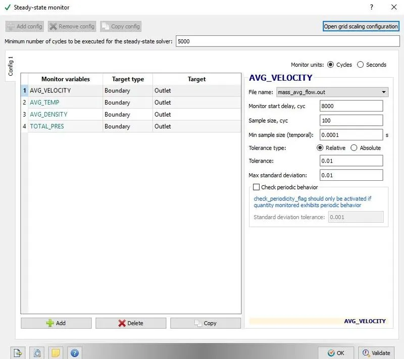
- The Monitor start display is a parameter that ensures that the simulation runs for a certain number of cycles before the variable can be monitored. This is especially useful in transient simulations when we want the solution to run for a particular amount of time before checking the convergence, if the steady state results are also required.
- Sample size denotes the number of cycles or seconds over which the variable is checked to see if the solutions have converged.
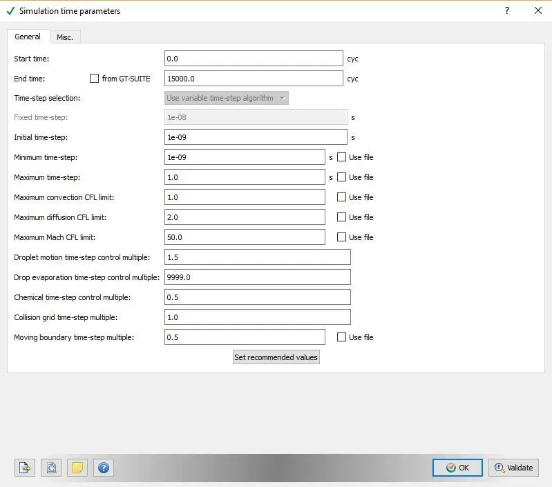
- Then under the Simulation Time Parameters assign the End time and look after the Maximum Convection CFL limit and assign with 1.
- Then click on Solver Parameters [Steady-state] --> Equations --> Pressure --> Make sure that the Preconditioner is set to None. Then under the Steady-state solver control assign the maximum convection CFL limit (final stage) to less than 1 --> Click on Validate --> Click on OK.
- Then under the Initial conditions and Events --> Regions and Initialization --> add a region and rename it as Volumetric Region User Defined by using the F2 option
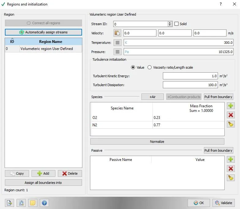
- Then under the boundary conditions assign the region names to the named boundary regions.
- Then under the physical models check the turbulence modelling and set with Reynolds Averaged Navier-Stokes (RANS) and set the turbulence model with RNG K-epsilon.
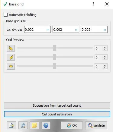
- Then in the Grid Control parameter --> Base Grid --> Enter the size of the grid.
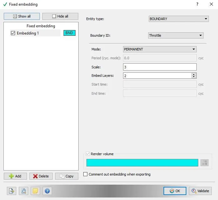
- Then in the Grid control parameter check the "Fixed Embedding" option.
- Enter the values for fixed embedding.
- Then under Output/Post-Processing --> Post Variable Selection --> Add the Mass fraction with O2 and N2
- Then under the Output files --> Writing time intervals --> set the time interval for writing 3D output data files and time interval for writing restarting output.
- Then use CYGWIN to execute the CFD solver.
- Then with the help of Converge CFD the post converting the output files to paraview format is done.
- Paraview is used for Post processing the results.
Results:
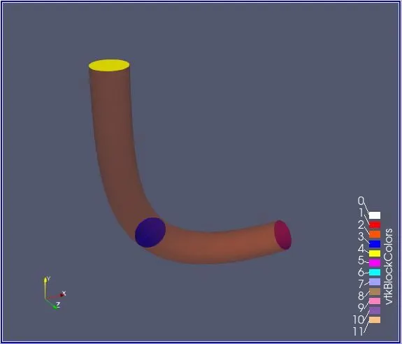
Mesh:
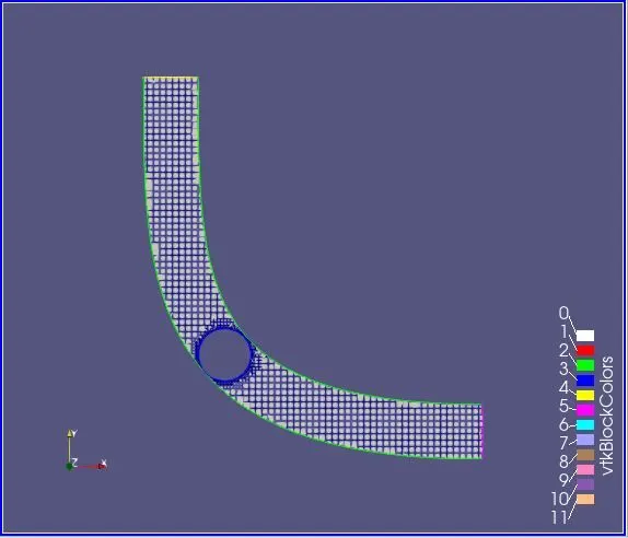
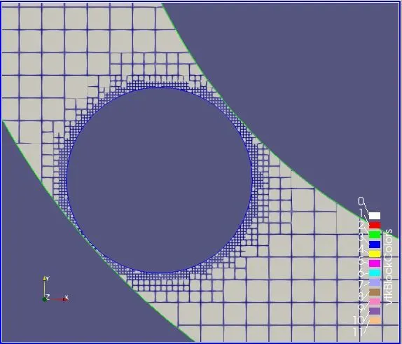
In order to make the mesh really fine near the throttle Fixed embedding is done so that the amount of fluid flow near the throttle leaks through the passages can be accurately calculated.
Velocity Contour:
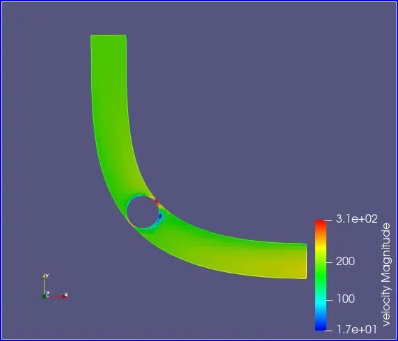
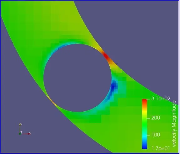
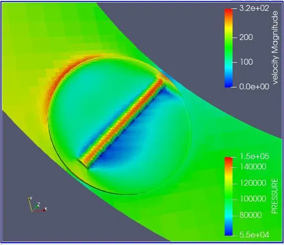
In this velocity contour we could predict that the velocity drastically increases at the throttle stage and decreases after the throttle.
Pressure Contour:
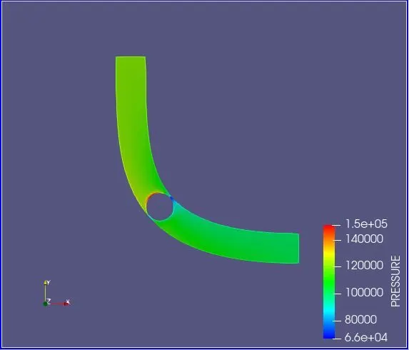
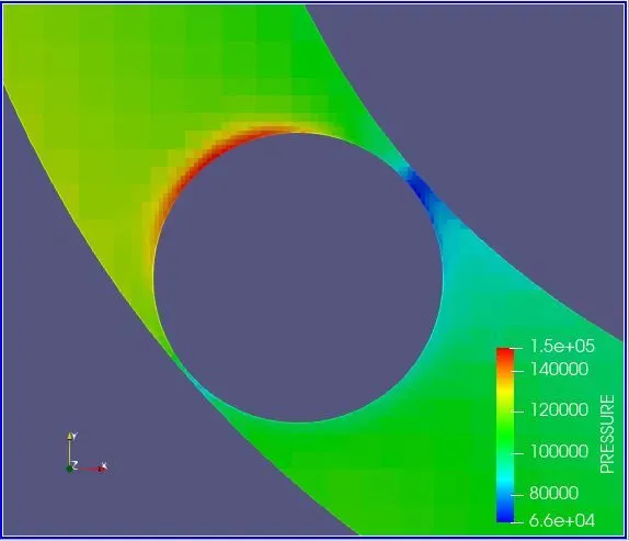
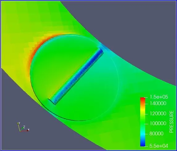
Through this pressure contour we could predict that the pressure increases drastically when the air hits the throttle and it decreases near the elbow walls. The increase in pressure is due to the stagnation and the pressure become normal after the throttle stage.
Mass flow rate plot:
Velocity plot:
Pressure plot:
Total Cell Count:
Velocity Animation:
Conclusion:
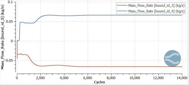
- The flow over the throttle body simulation have ran successfully showing the steady state flow behaviour.
- Due to restriction of the throttle, there are area of low velocity around the throttle body where as there are areas of high velocity and low pressure just below the throttle body.
- Fixed embedding around the throttle body increased the total cell count.