Week 4.1: Project - Steady state simulation of flow over a throttle body
Assignment number 03
Assignment Name- Steady State Simulation of flow over throttle body using converge
Objective
- Simulate flow over throttle body
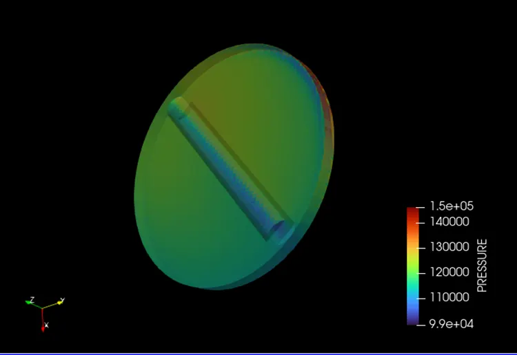
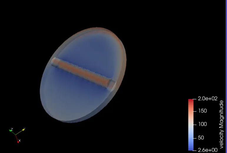
- Post process results and show Pressure contours and velocity contours
- Show Mesh (Surface with edge)
- Create the animation in which throttle movement should be visible
Steps
- Imported STL file in converge studio
- Setup the case
- Run the simulation in Cygwin
- Post process the results in PARAVIEW
Theory
Throttle:
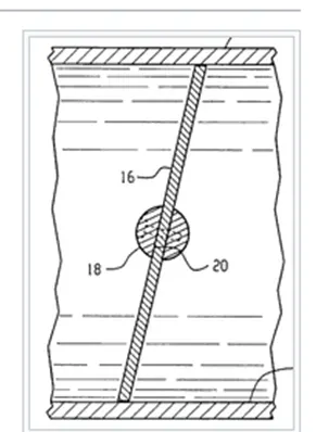
A Throttle is a mechanism by which fluid flow is managed by constriction or obstruction.Engine power can be increased or decreased by the restriction of inlet gases. Term throttle has come to refer, informally to any mechanism by which the power or speed of an engine is regulated such as car accelerator pedal. Throttle is a device controlling the flow of fuel or power to an engine
Geometry
- Import STL files
- Cad cleans up means we don’t need thick pipe wall because it is nowhere useful to participate in the simulation. So, we will delete outer surface
- Then we used patch command for closing the open edges
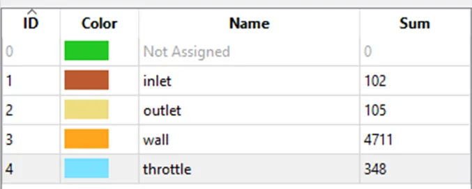
- Then give boundary flagging
- Then check normal transformation, all the face normal direction should be facing towards the flow region
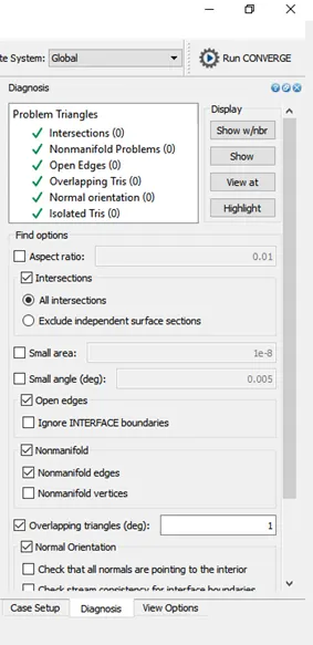
- And finally, diagnosis
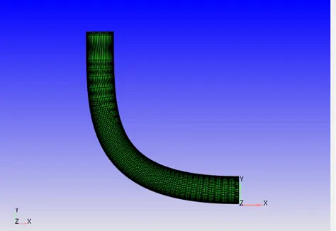
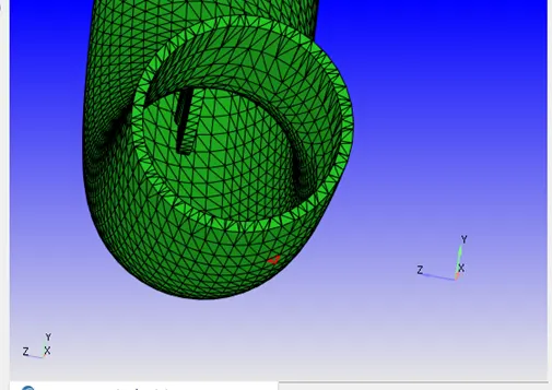
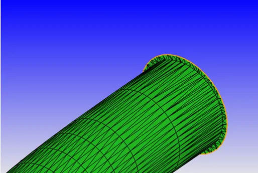
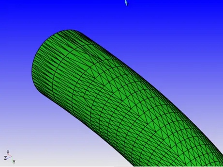
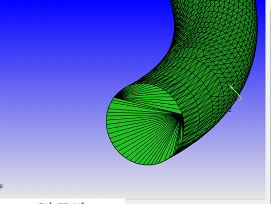
Click on boundary and Create boundary
Checking normal
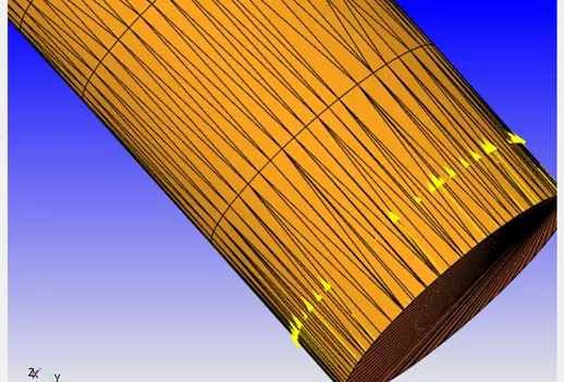
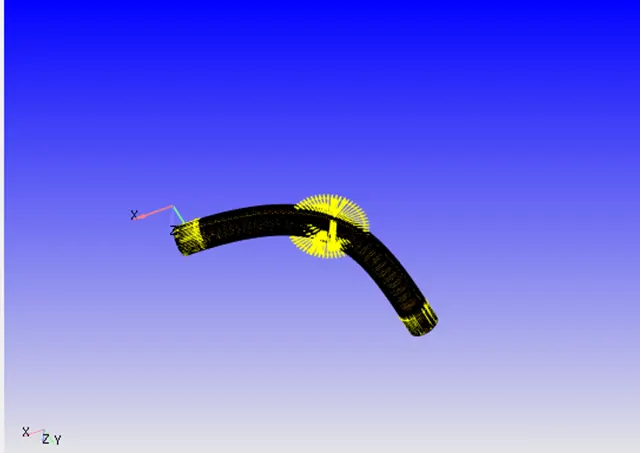
Before proceeding the error in geometry for that
View tab-diagnosis dock-default setting-select the find
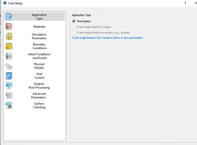
Case Setup
Application Type = Time-based
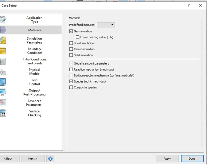
Materials -
Predefined mixtures = Air
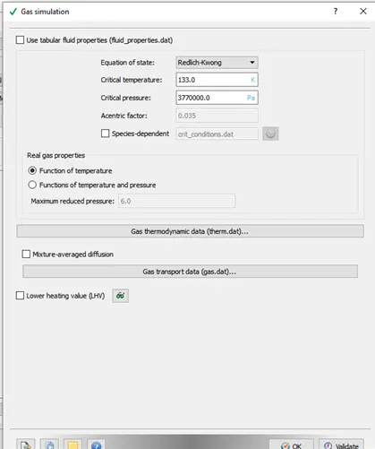
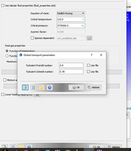
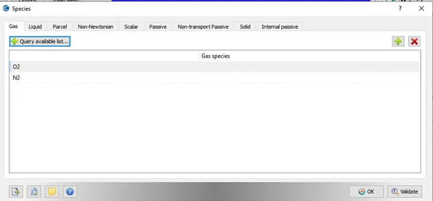
Simulation Parameters-
In Run Parameters two main things to be considered: -
select the following solver settings.
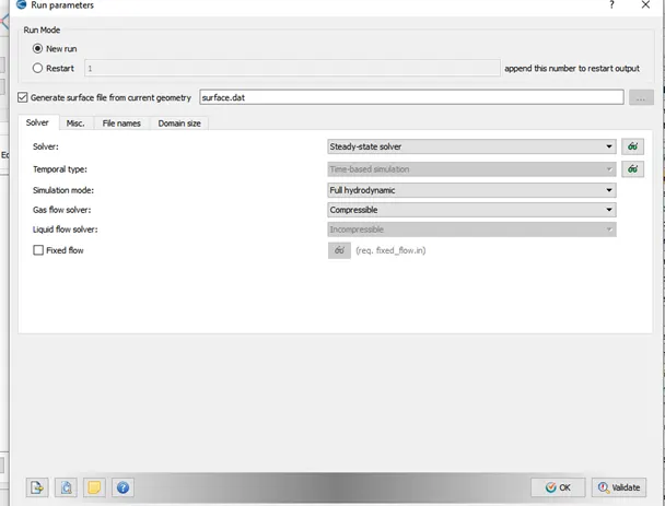
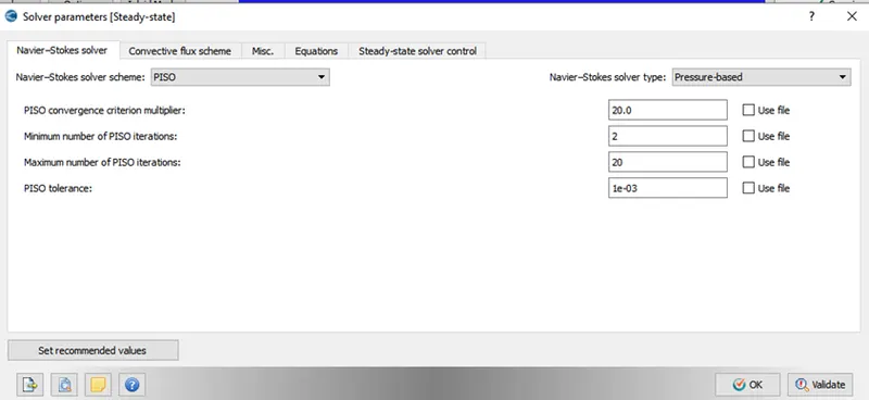
Solver Parameters [Steady-State]-
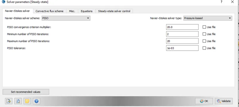
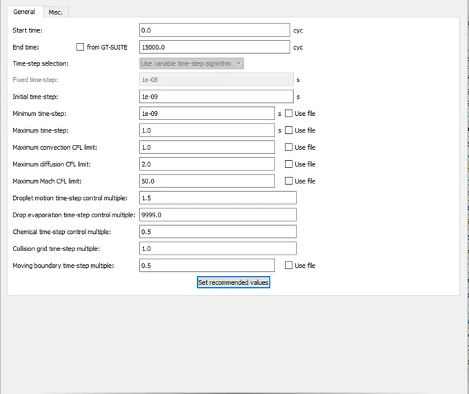
Simulation Time Parameters: -
Pressure based steady state solver
Start time-0
End time-15000 cycle
Initial time step-1e-09s
Minimum time step-1e-09s
Maximum time step-1s
Navier-Strokes Solver type- pressure based
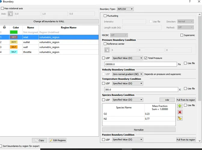
Boundary condition
Inlet-inflow-total pressure-150000 pa
Outlet-outflow-total pressure-100000 pa
Elbow wall-wall
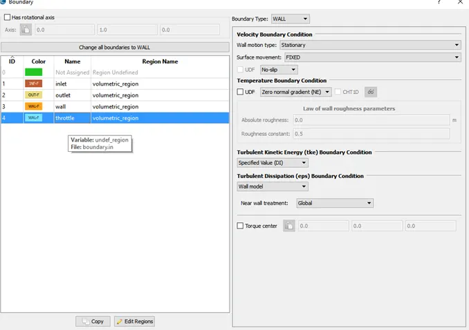
Throttle-wall
inlet
outlet
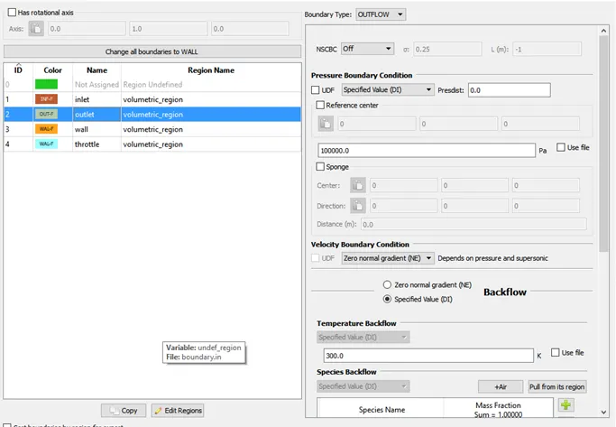
Elbow wall
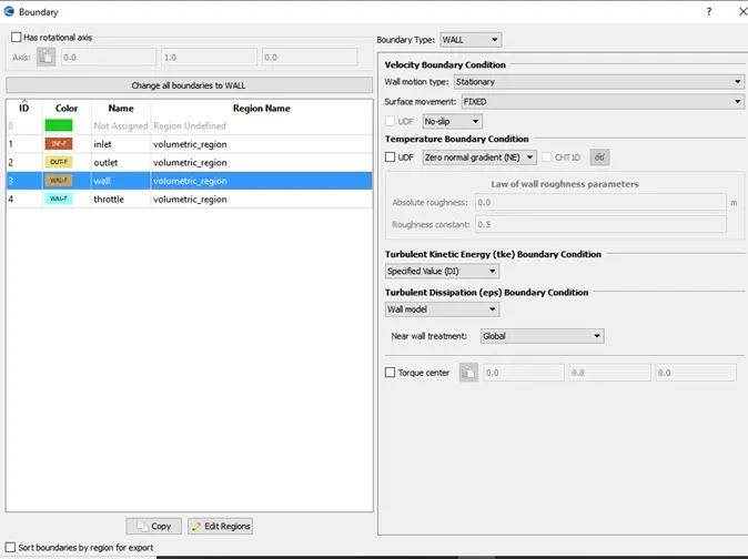
Throttle wall
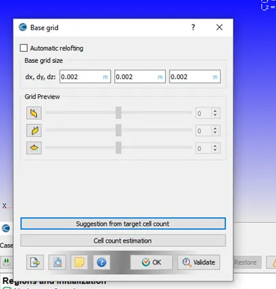
Base grid
Fixed embedding
At throttle
Type-boundary, mode-permanent
Scale-3, embed layer-2
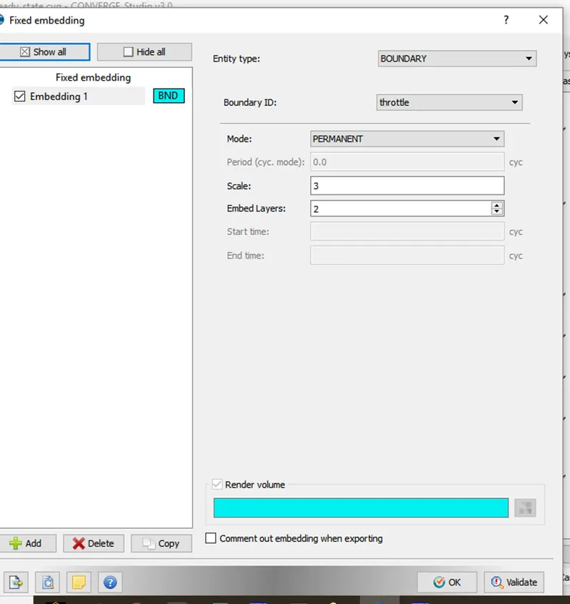
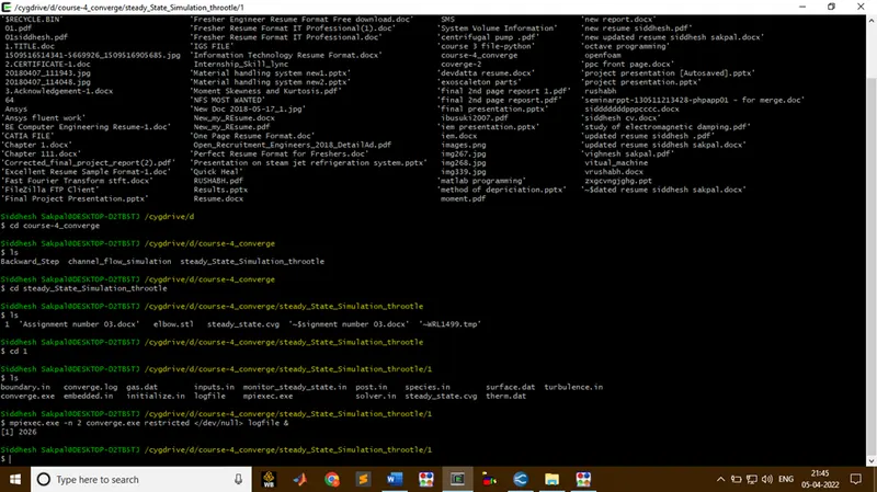
Note: check green tick mark on each option in case setup
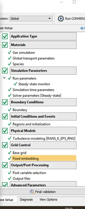
Cygwin Window
Results
Mesh
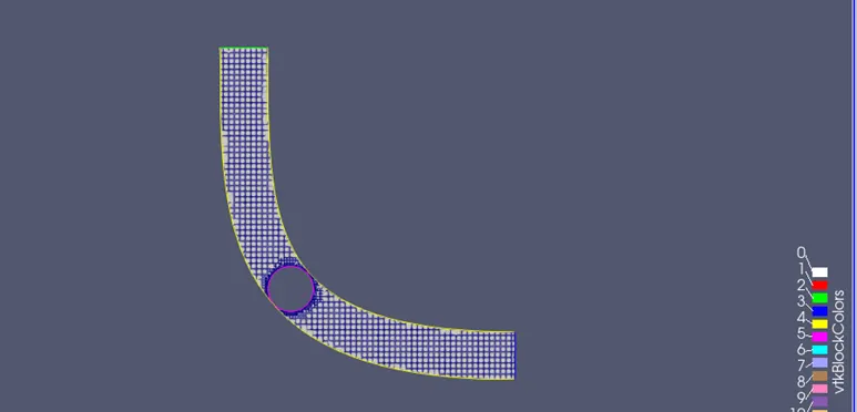
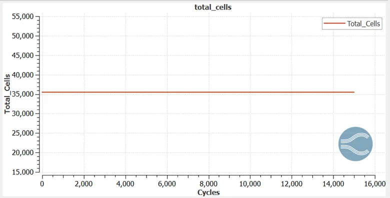
Total of cells
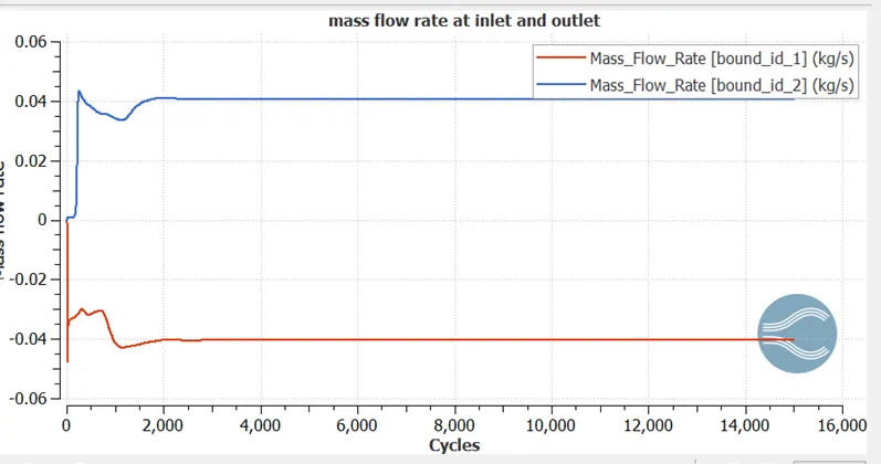
Mass Flow rate
Inlet And Outlet
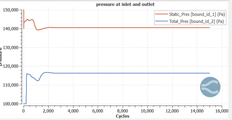
Pressure plot
Inlet and Outlet
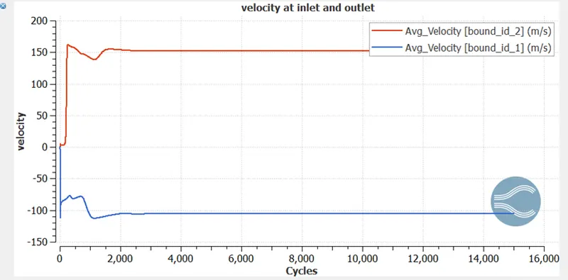
Velocity plot
Inlet and Outlet
Pressure contour
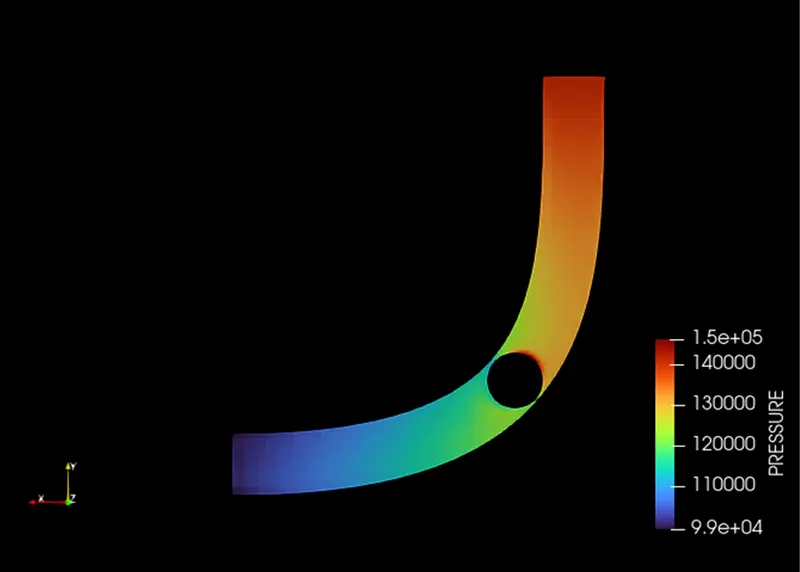
Pressure contour at throttle
Velocity contour
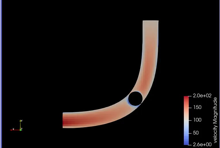
Velocity contour at throttle
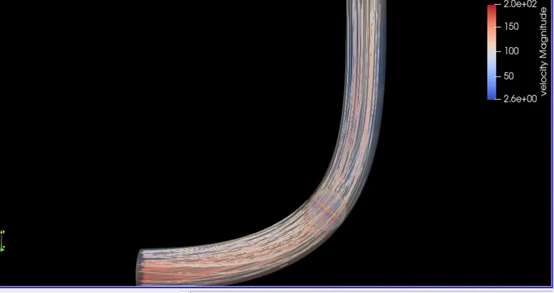
Stream trace:
Video link-https://www.youtube.com/watch?v=FF6grUYGR5M
Conclusions
- In these assignments we perform steady state simulation of flow over throttle body
- We observe the red zone near the throttle wall it is because of high pressure air coming from inlet
- Embedding is given because it ensured detailed physics near the wall