Week 4.1: Project Steady state simulation of flow over a throttle body
AIM:
To simulate flow over a throttle body as steady-state simulation.
FLOW OVER THROTTLE BODY:
Here inflow over a throttle body, we find the pressure difference over the throttle body using steady-state simulation.
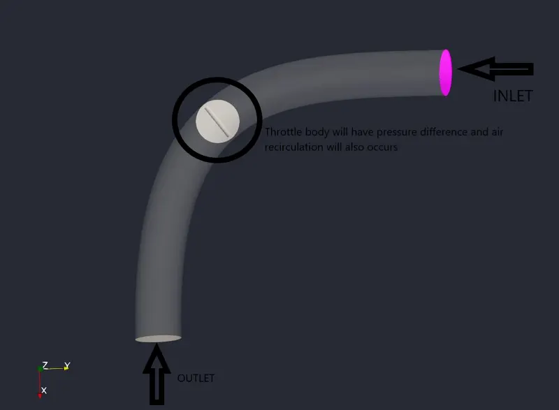
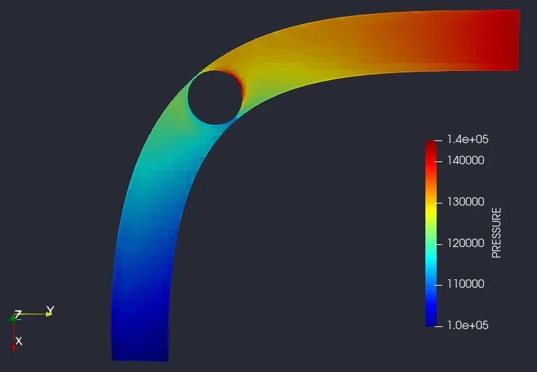
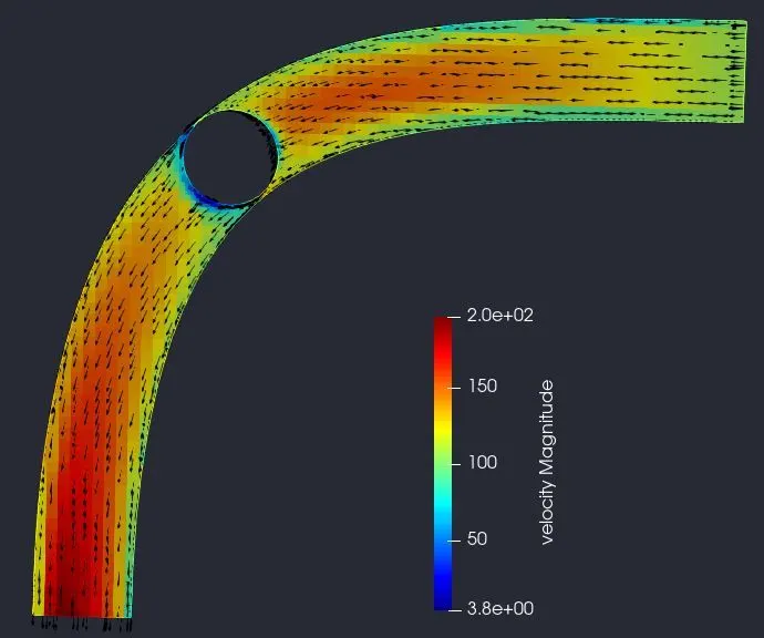
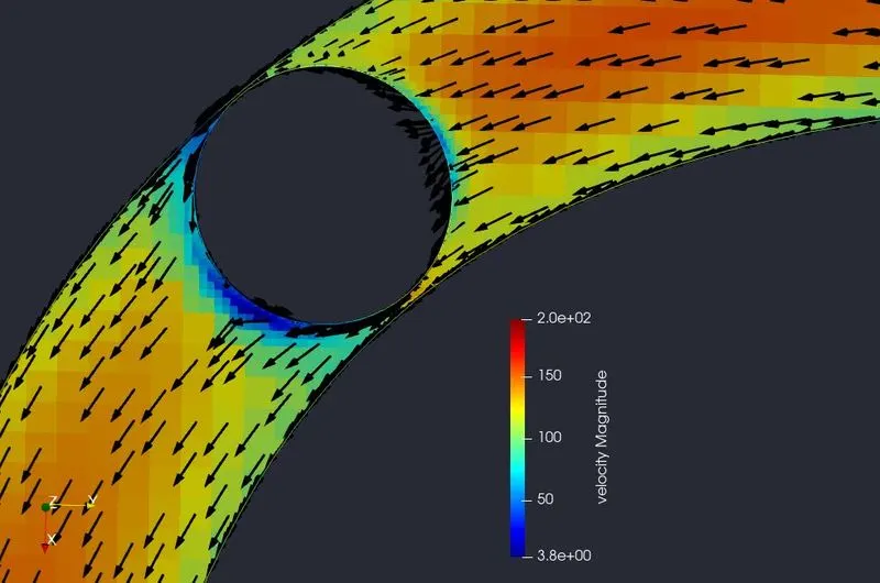
In throttle body due to pressure difference in flow turbulence occurs. Due to turbulence, flow air is recirculated in this region. Pressure is high at the inlet portion of the throttle body and low pressure at another end of the throttle body. If there is a change in pressure then velocity also changes in this region as vice-versa.
CASE STEUP FOR SIMULATION:
Case set-up :
- The application type is Timebase.
- A predefined air mixture is used.
- Using turbulent Prandtl number 0.9.
- Using turbulent Schmidt number 0.78.
- O2 and N2 are species of air.
Simulation Parameters:
- A steady-state solver is used.
- Starting cycle is 0 and the ending cycle is 15000.
- The initial time step is 1e-9s.
- The minimum time step is 1e-9s.
- The maximum time step is 1s.
- A pressure-based solver is used.
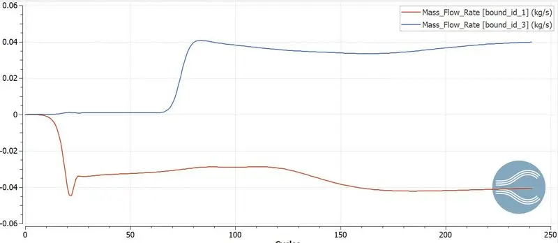
- The steady-state monitor is turned on, Mass flow rate is selected.
- The minimum number of cycles to execute for the steady-state monitor is 5000 cycles.
Boundary Condition and Region Initialization:
- Inlet, Outlet, throttle, and elbow wall total of four boundaries are used.
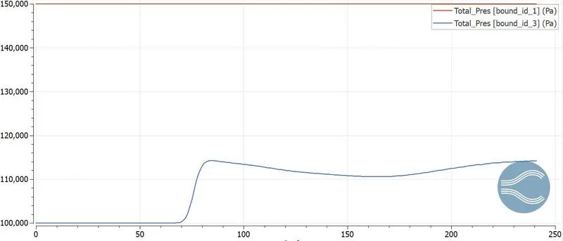
- Inlet is considered as Inflow and has a pressure of about 1.5e5 pa, in species we have air.
- The outlet is considered as Outflow and has a pressure of about 1e5 pa, if we have backflow then we have air as species.
- The elbow wall is considered a No-slip condition.
- The throttle body is also considered a No-slip condition.
- In region initialization, we will a region where the fluid should flow and we assign this in the boundary condition.
- Species in region initialization is also air.
Physical Model:
- We are using RANS_K_EPS_RNG ( Re-Normalisation Group) turbulence model.
Grid Control:
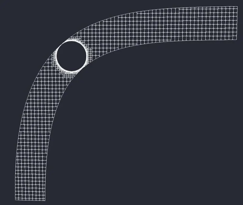
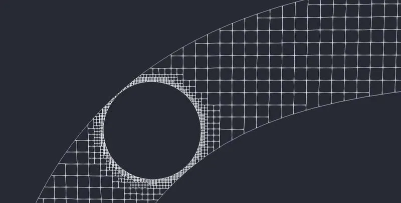
- In grid control, we will be defining the mesh size for the domain (0.002 m is the mesh size).
- Now we are going to enable Fixed embedding.
- In fixed embedding, we are going the define where the mesh is to be refined so we can capture the flow properties very accurately without decreasing the mesh size.
Output and Post-processing:
- In the post-variable selection, we can select the output that we need for post-processing.
- In output files, we can set time intervals for writing the 3D output.
- We can also set time intervals for writing, restarting files.
Running Simulation:
- After finishing setting up the simulation case we need to export the input files in a folder.
- Now open the Cygwin terminal and navigate to the folder where you exported the input files.
- Now run the executable mpiexec.exe -n 2 converge.exe restricted.
- After finishing the simulation we need to convert the output file to paraview format.
- mpiexec.exe -n 2 post_convert_30_msmpi_64.exe command is used to convert the file as ParaView format.
RESULT:
MESH GENERATION:
PRESSURE CONTOUR:
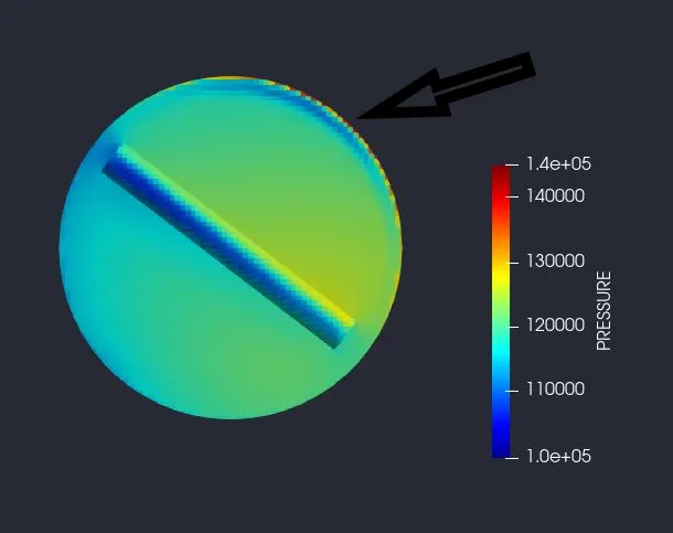
Stagnation point:
The point where pressure is too high and velocity is zero is called the Stagnation pressure point. (This is vice-versa for velocity)
VELOCITY CONTOUR:
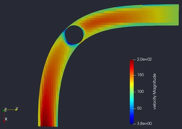
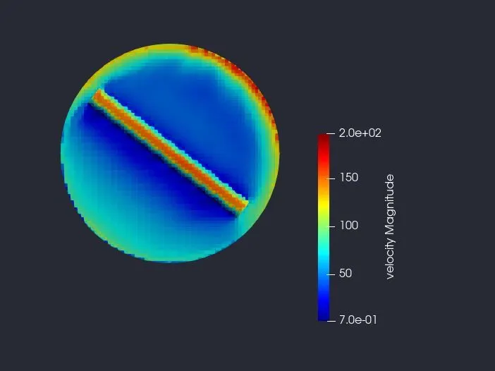
VECTOR PLOT OVER THE THROTTLE BODY:
MASS FLOW RATE PLOT:
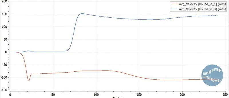
AVERAGE VELOCITY PLOT:
TOTAL PRESSURE PLOT:
ANIMATION OF VELOCITY CONTOUR:
ANIMATION OF PRESSURE CONTOUR:
CONCLUSION:
- From this simulation, we understand flow over the throttle body in steady-state simulation.
- Understanding the concept of stagnation point over the throttle body.