Week 4.1: Project - Steady state simulation of flow over a throttle body
AIM
Simulate the steady-state flow over a throttle pipe using converge and discuss the results obtained for velocity, pressure and mass-flow rate contour.
INTRODUCTION
In this project, I used a steady state solver for simulation of throttle valve using CONVERGE cfd.
For turbulent model Pressure based solver with RNG k-epsilon is used for simulation.
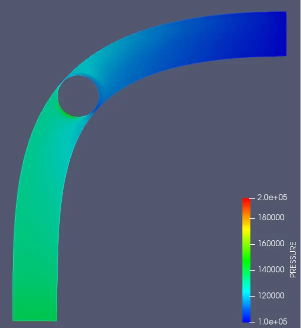
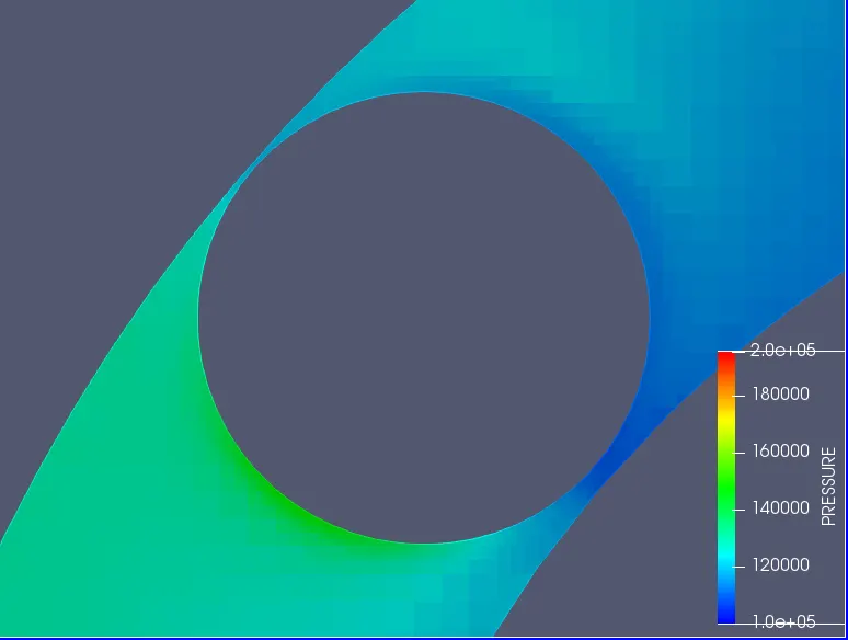
Parameters like mass flow rate, velocity distribution, pressure variation across the throttle region is observed and analyzed.
Embedded scaling is done to refine the mesh around the throttle interface regions to achieve and capture the physics of flow accurately where the main flow disturbance is held.
At last I have created animation for my result for velocity contour at different time-steps.
THEORY
A throttle is a very fundamental intrument in fluid applicatio working on a mechanism by which fluid flow is managed by constriction or obstruction.
In an IC engine the throttle is a means of controlling an engine's power by adjusting the amount of fuel or air entering the engine. In a motor vehicle the control used by the driver to manage power is sometimes termed the throttle, accelerator, or gas pedal.
With a gasoline engine, the throttle most often adjusts the amount of air and fuel permitted to enter the engine. Recently, for a GDI engine, the throttle governs the amount of air allowed to enter the engine. The throttle of a diesel, when present, regulates the air flow into the engine.
But in modern engines of both types (gas and diesel) are commonly driven by the wire systems where sensors monitor the driver controls and in response a computerized system controls the flow of fuel and air.
The throttle on a gasoline engine is typically a butterfly valve. In a fuel injected engine, the throttle valve is placed on the entrance of the intake manifold, or housed in the throttle body.
In a carbureted engine, it is found in the carburetor. When a throttle is wide open, the intake manifold is usually at ambient atmospheric pressure. When the throttle is partially closed, a vaccuum develops as the intake drops below ambient pressure.
PREPARING GEOMETRY
1) Load the downloaded geometry and delete the extra unnecassary surfaces
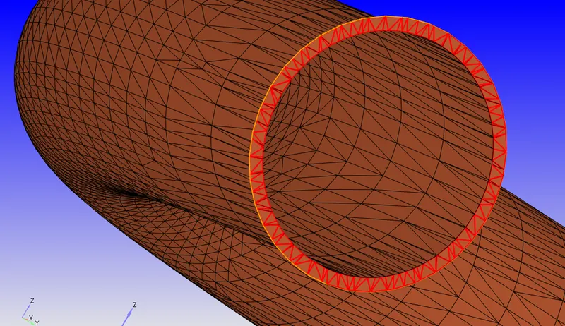
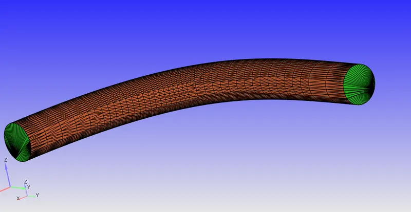
2) Close the geometry by patching the inlet and outlet surfaces
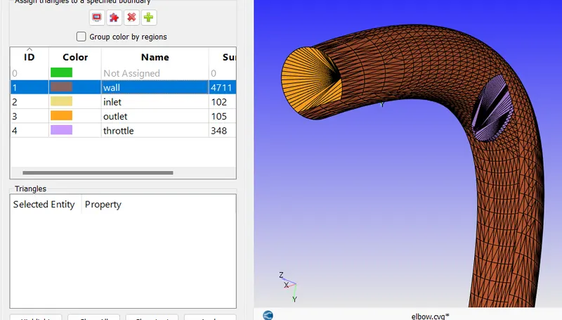
3) Assign the boundaries to surfaces as suitable
CASE SETUP
We need to achieve the following results at the end of setup
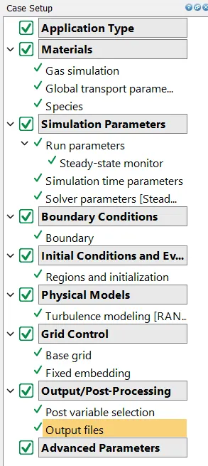
Choose the time based solver
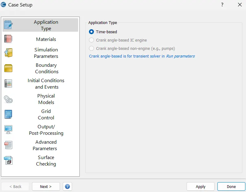
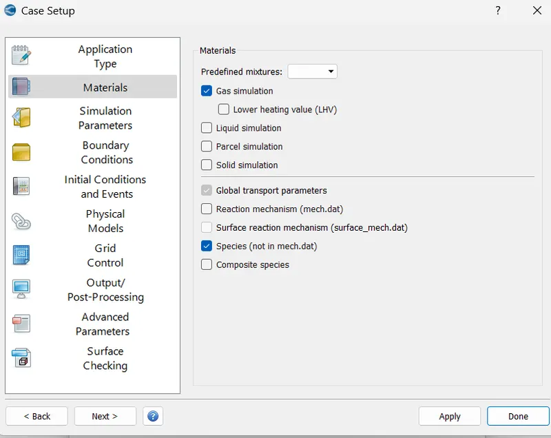
Set the follwing material type
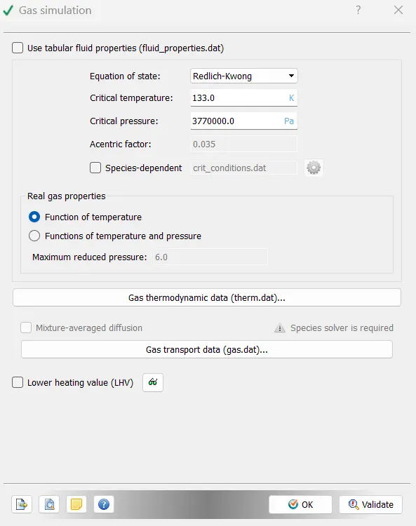
Gas simulation
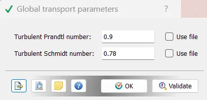
Set the parameters
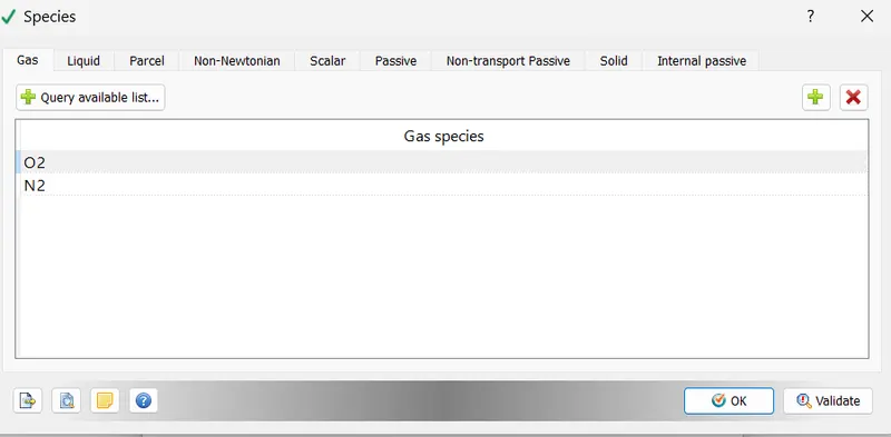
Define the following species
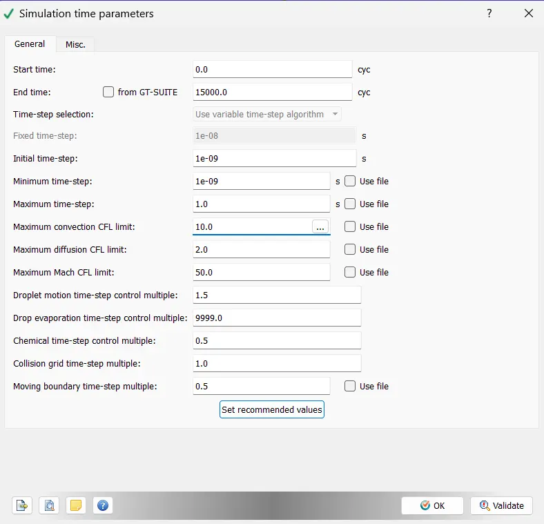
Define simulation para
Define the boundaries
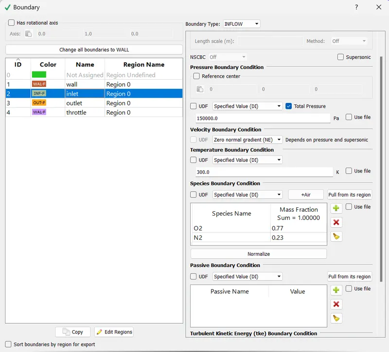
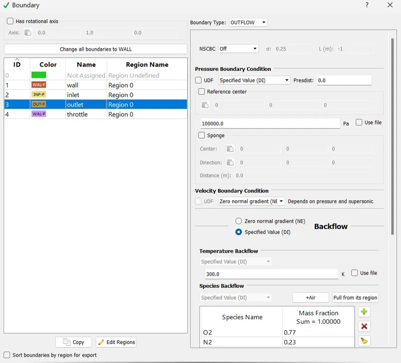
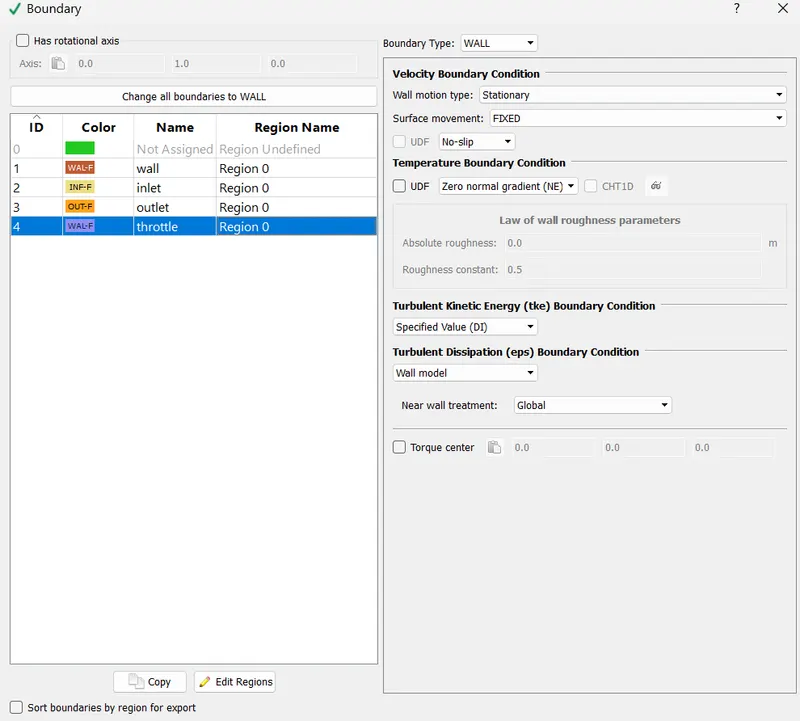
Define the regions
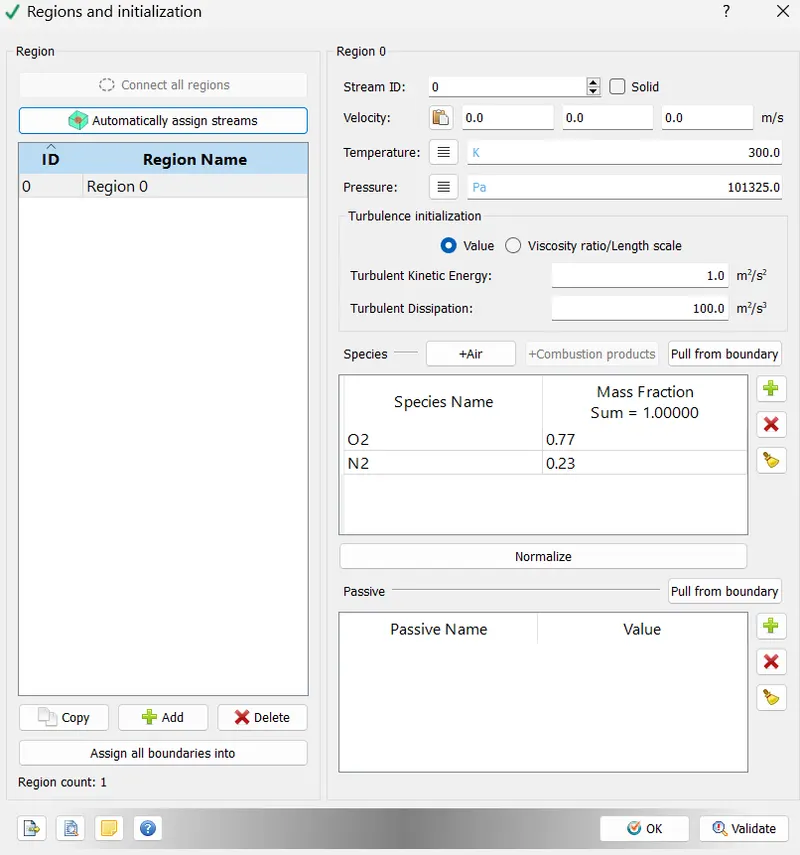
Give the following mesh properties
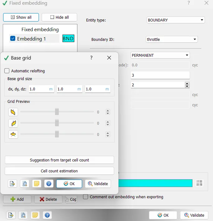
Dump the output files after every 100 cylcles
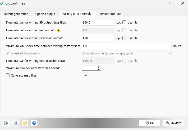
RESULT
Mesh near the throttle

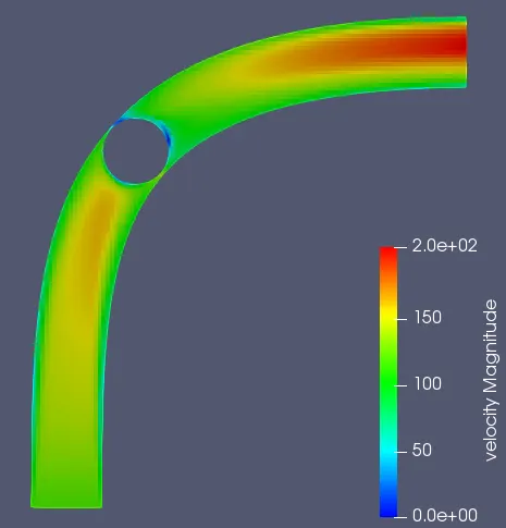
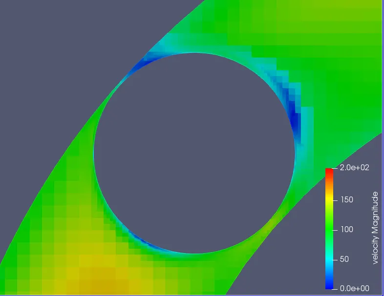
Velocity behaviour
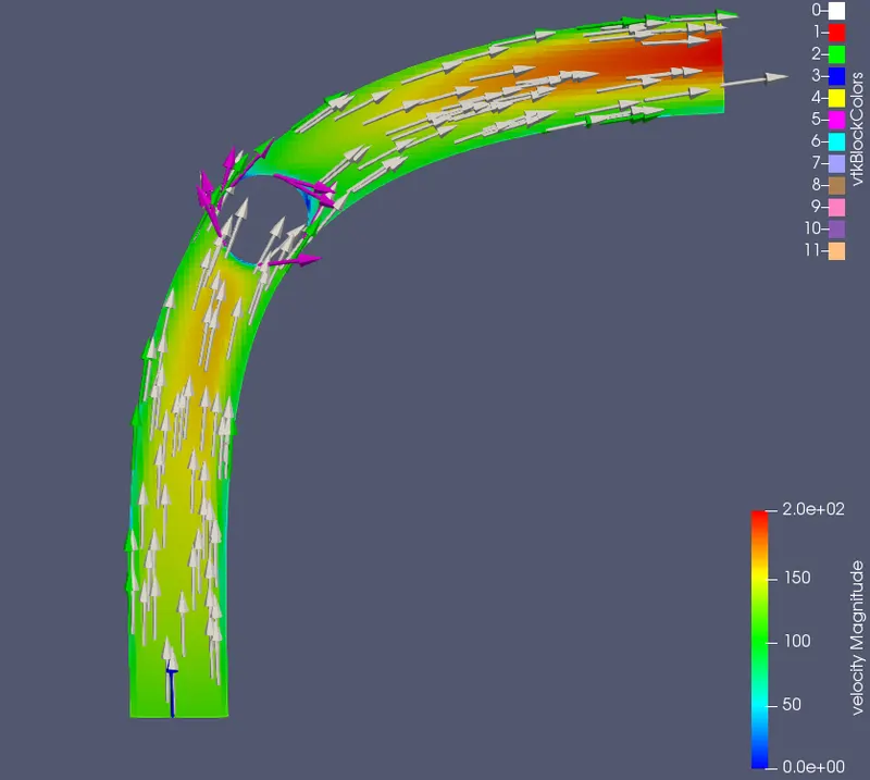
Vector Reprresentation
Pressure behaviour
PLOTS
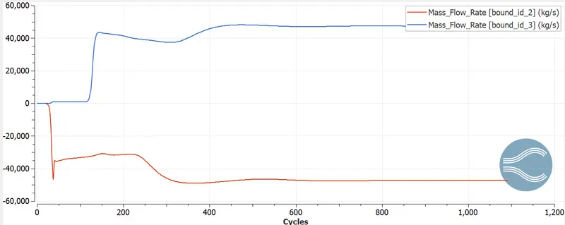
Mass-flow rate
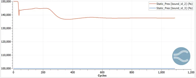
Pressure
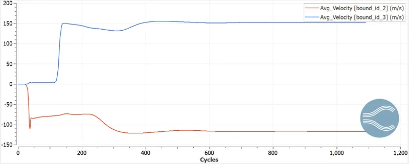
Velocity
CONCLUSION
FRom the result obtained we can conclude the following observations:-
1) Mass-flow variation is observed around the throttle region.
2) Regions with difference in velocity magnitude around the throttle body is observed.
3) After good number of cycles, steady state is achieved for all observed parameters.
4) Grid refinement gives us better and accurate results for parameters around throttle too.
VELOCITY ANIMATION