Week 3 Verification of Weld Joints
AIM: The aim of this week challenge is to perform a weld joint test on the given model for different material for welds and explain the result for various stress and strain plots.
PROCEDURE:
CASE 1:
step 1: Open the ansys workbench module and select the static structural analysis.
step 2: Now open the engineering data for material and add stainless steel,aluminium alloy and also manually add bronze material
step 3:After adding all the three material, right click the geomentry tab and select import geomentry --> browse --> select the file --> open.
step 4: After importing the model open the mechanical model in ansys.
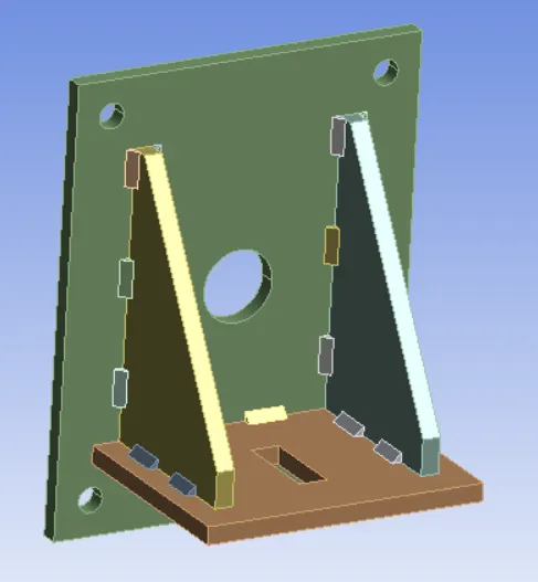
step 5: Now assign the material for all the plates, ribs and welds.
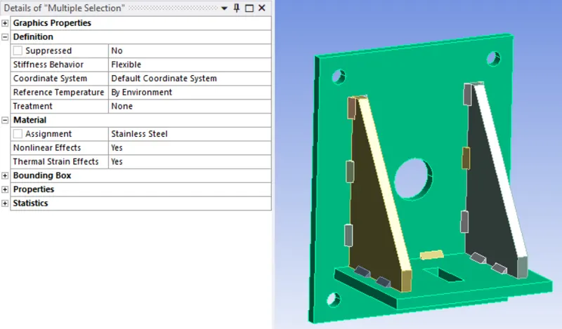
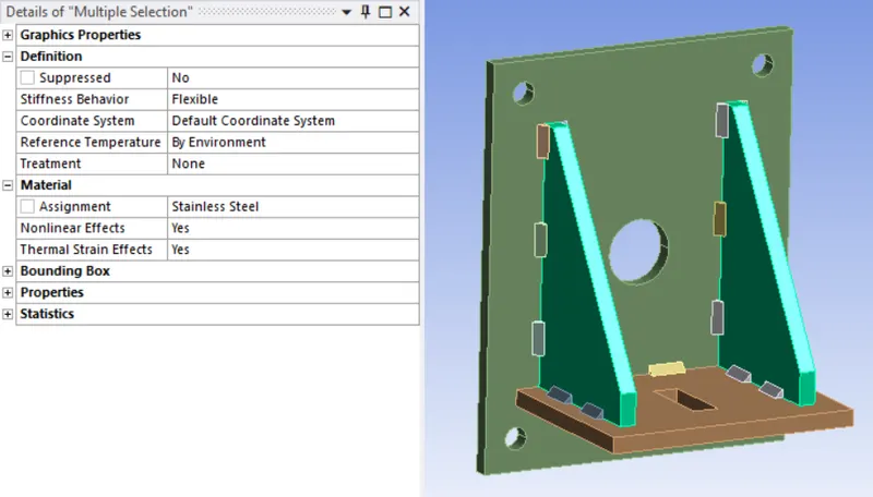
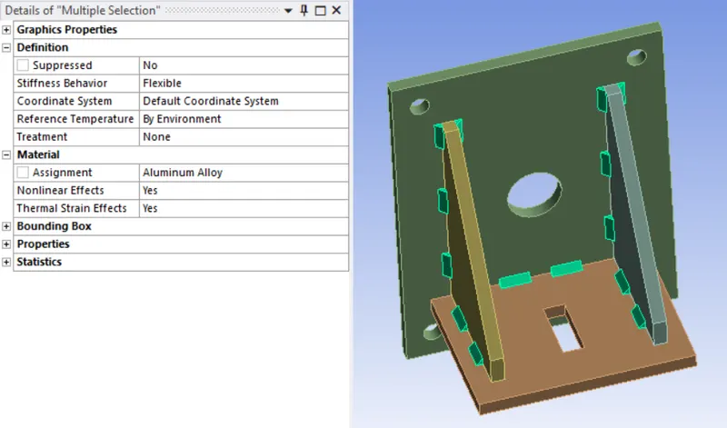
step 6: Now change the mesh size of the plates and ribs to 7mm and for the welds give the mesh size as 4mm.
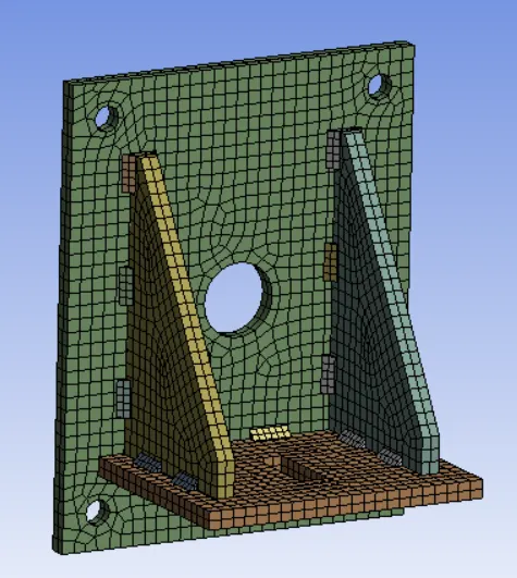
step 7: Now create bonded contact for all the weld elements and frictional contact for all the other plate and ribs contacts.
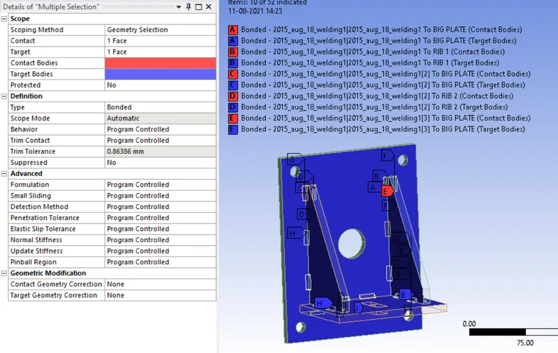
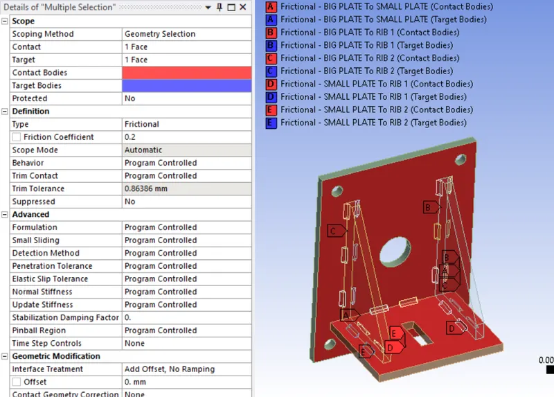
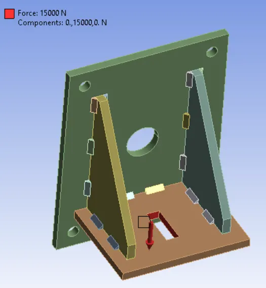
step 8: Now create fixed support on all the bolt position on the big plate.
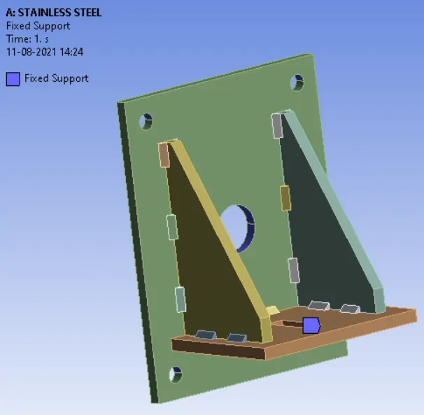
step 9: Now apply a load of 15000N on the rectangular hole in the small plate.
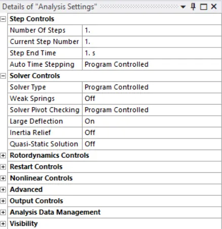
STEP 10: Now change the analysis settings and ON the large deflection.
step 11: Now run the simulation.
step 12: Now include the total deformation,Equivalent stress and strain in output files.
step 13: Now increase the bearing load and run the simulation.
Step 14: Compare the result plot and give a detailed explanation.
OUTPUT FILE:
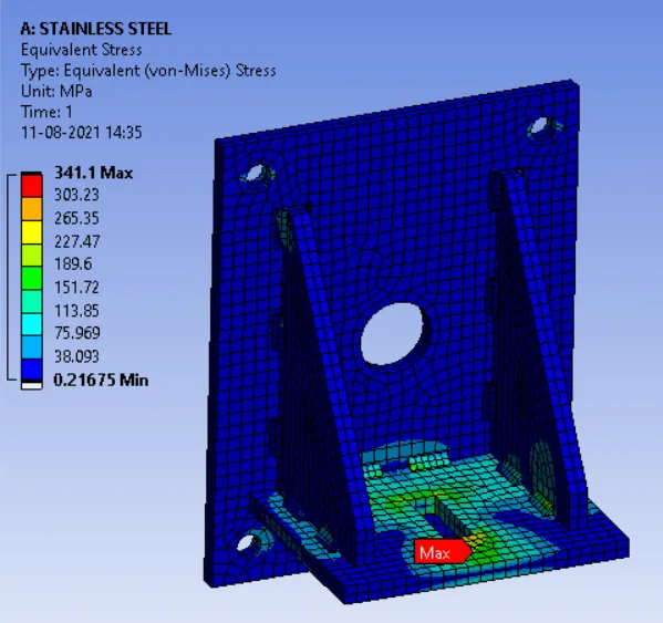
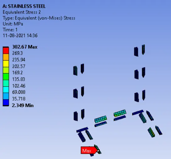
EQUIVALENT STRESS:
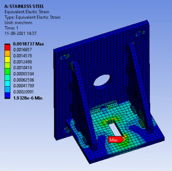
EQUIVALENT STRAIN:
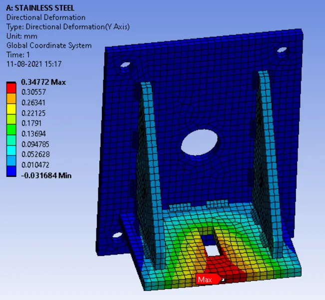
DIRECTIONAL DEFORMATION:
CASE 2:
step 1: Open the ansys workbench module and select the static structural analysis.
step 2: Now open the engineering data for material and add stainless steel,aluminium alloy and also manually add bronze material
step 3:After adding all the three material, right click the geomentry tab and select import geomentry --> browse --> select the file --> open.
step 4: After importing the model open the mechanical model in ansys.
step 5: Now assign the material for all the plates, ribs and welds.
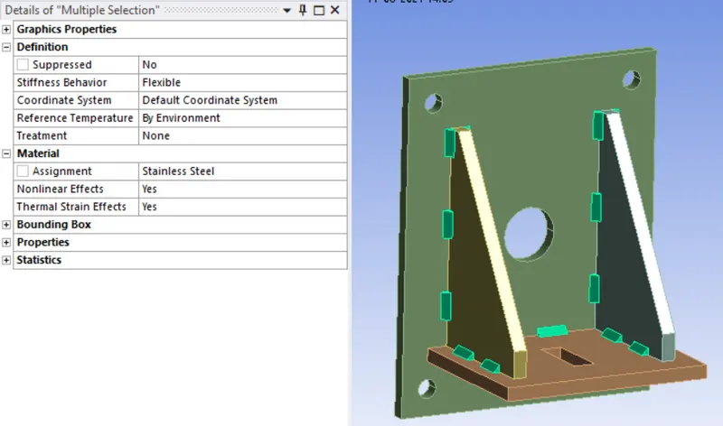
step 6: Now change the mesh size of the plates and ribs to 7mm and for the welds give the mesh size as 4mm.
step 7: Now create bonded contact for all the weld elements and frictional contact for all the other plate and ribs contacts.
step 8: Now create fixed support on all the bolt position on the big plate.
step 9: Now apply a load of 15000N on the rectangular hole in the small plate.
STEP 10: Now change the analysis settings and ON the large deflection.
step 11: Now run the simulation.
step 12: Now include the total deformation,Equivalent stress and strain in output files.
step 13: Now increase the bearing load and run the simulation.
Step 14: Compare the result plot and give a detailed explanation.
OUTPUT FILE:
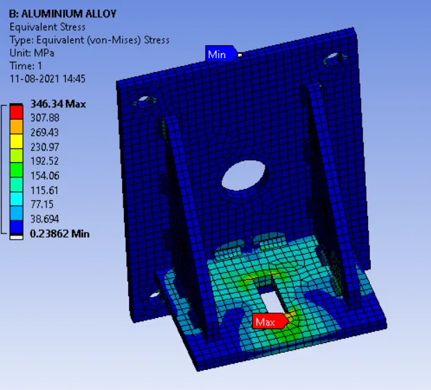
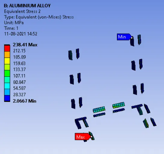
EQUIVALENT STRESS:
DIRECTIONAL DEFORMATION:
CASE 3:
step 1: Open the ansys workbench module and select the static structural analysis.
step 2: Now open the engineering data for material and add stainless steel,aluminium alloy and also manually add bronze material
step 3:After adding all the three material, right click the geomentry tab and select import geomentry --> browse --> select the file --> open.
step 4: After importing the model open the mechanical model in ansys.
step 5: Now assign the material for all the plates, ribs and welds.
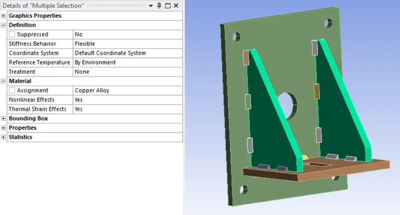
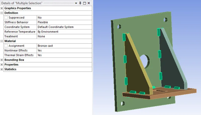
step 6: Now change the mesh size of the plates and ribs to 7mm and for the welds give the mesh size as 4mm.
step 7: Now create bonded contact for all the weld elements and frictional contact for all the other plate and ribs contacts.
step 8: Now create fixed support on all the bolt position on the big plate.
step 9: Now apply a load of 15000N on the rectangular hole in the small plate.
STEP 10: Now change the analysis settings and ON the large deflection.
step 11: Now run the simulation.
step 12: Now include the total deformation,Equivalent stress and strain in output files.
step 13: Now increase the bearing load and run the simulation.
Step 14: Compare the result plot and give a detailed explanation.
OUTPUT FILE:
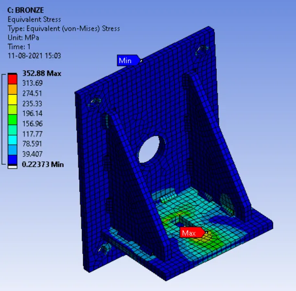
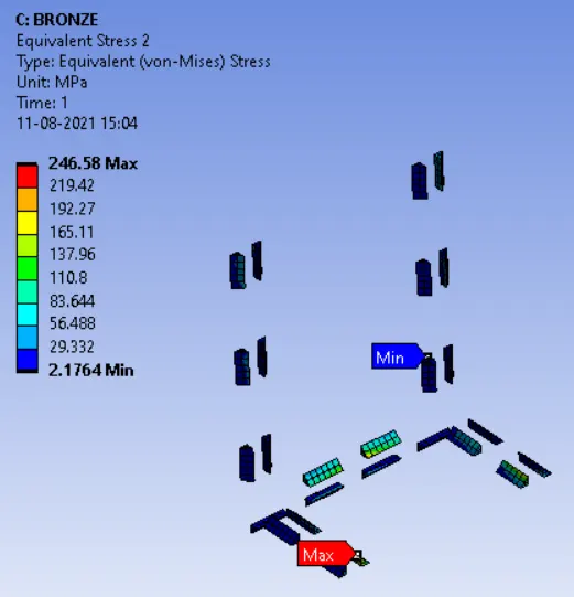
EQUIVALENT STRESS:
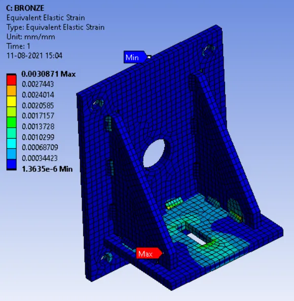
EQUIVALENT STRAIN:
DIRECTIONAL DEFORMATION:
CONCLUSION:
| Equivalent stress in Mpa | Equivalent stress in weld in Mpa | Equivalent strain in mm | |||||
| min | max | min | max | min | max | ||
| Stainless steel | 0.216 | 341.1 | 2.349 | 302 | 1.90E-06 | 0.00187 | |
| Aluminium alloy | 0.238 | 346.34 | 2.0667 | 238.41 | 1.94E-06 | 0.00323 | |
| Bronze | 0.22373 | 352.88 | 2.176 | 246.58 | 1.36E-06 | 0.00308 | |
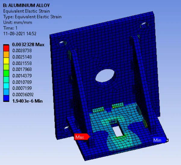
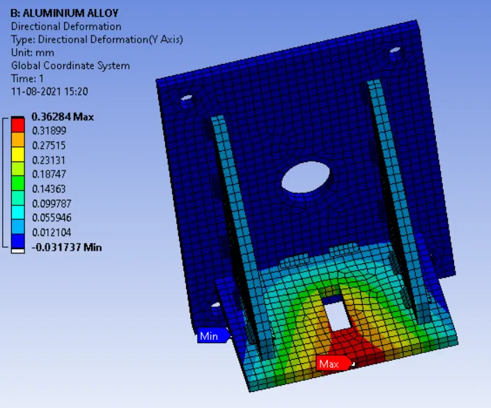
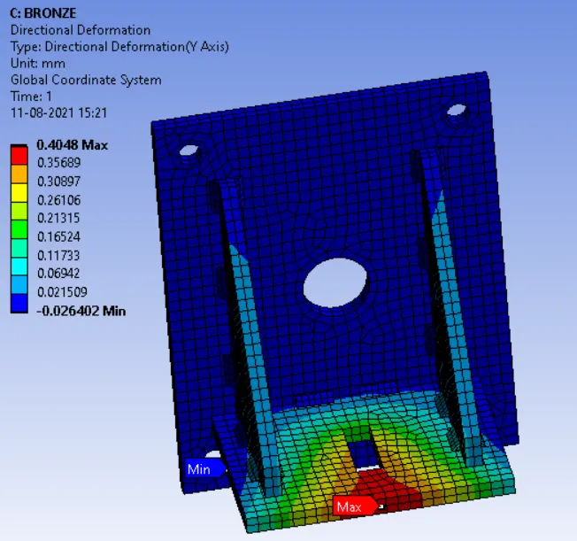
Based on the above result, the maximum stress is created in the third case and the stress is minimum in case 1.For all the three cases the stress is maximum at the same location.Then for the stress created at the weld alone, stainless steel has the maximum stress created and aluminium has the least stress. In this case also the maximum stress location is same for all the three cases. The strain rate is maximum for case 2 and for case 3 it is almost similar to case 2 and for case 1 it has only half the strain as other two cases.The directional deformation is maximum in case 3 and minimum in case 1.