Week 3 Verification of Weld Joints
Objective:
Static Structural Analysis simulation of Weld Joint structure including welds are analysed by Ansys software. There are 3 case studies and these are defined below.
Case 1. Stainless Steel: In this case, the material of the plates must also be the same. Use Stainless steel for both weldments and plates. No need to add flux to the weldments.
Case 2. Aluminium Alloy: The material to be chosen for this case is Aluminium alloy (high strength, wrought). [Plate material to be used is stainless steel]
Case 3. Bronze: In order to simulate "Brazing", you should be using bronze as the weld material. Assign Stainless Steel to both plates and Copper to the "Ribs".
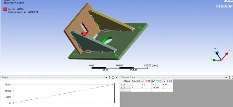
Run the simulation for a load of 15000N that is to be applied at the rectangular hole in the small plate (Same as in the video).
For each case, find out the Directional Deformation and equivalent strain experienced by the setup. Identify the weld joint that experiences the highest equivalent stress in each case and compare the results for all three cases.
Analysis Set Up:
Static Structural Analysis is carried for verifications of weld joints set up. The materials used are as per table given below and analysis is carried out in Ansys Workbench.
|
Plates |
Rib |
Weld |
|
|
Case 1 |
Stainless Steel |
Stainless Steel |
Stainless Steel |
|
Case 2 |
Stainless Steel |
Aluminium Alloy high strength wrought |
Aluminium Alloy |
|
Case 3 |
Stainless Steel |
Copper Alloy |
Bronze, Cast |
The Bracket welded structure set up geometry is imported and shown in figure below. The system consists of 2 Plates welded together and strengthened by ribs, each welded to both plates. Load of 15000 KN is applied in Y direction at the rectangular holes. Analysis is done for conditions required in Challenge Objectives. The analysis is required for 3 types of materials of weld and ribs with stainless plates.
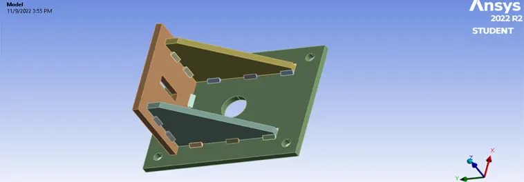
The analysis is done for one combination of materials and parametric for other materials. Analyses is done by Ansys software.
Materials Specifications: The following materials and specifications are used.
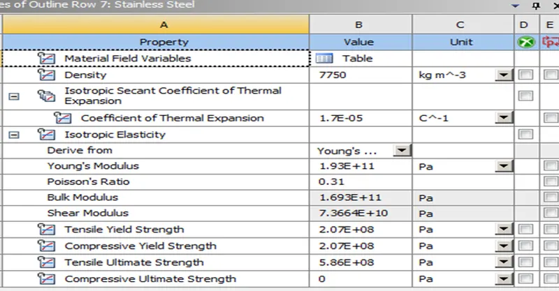
Stainless Steel: (Plates for all 3 cases, Ribs and weld material for Case 1)
Aluminium Alloy: (For weld of Case 2)
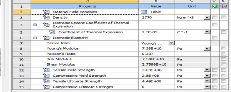
Aluminium Alloy:(High Strength, Wrought) for ribs of Case 2
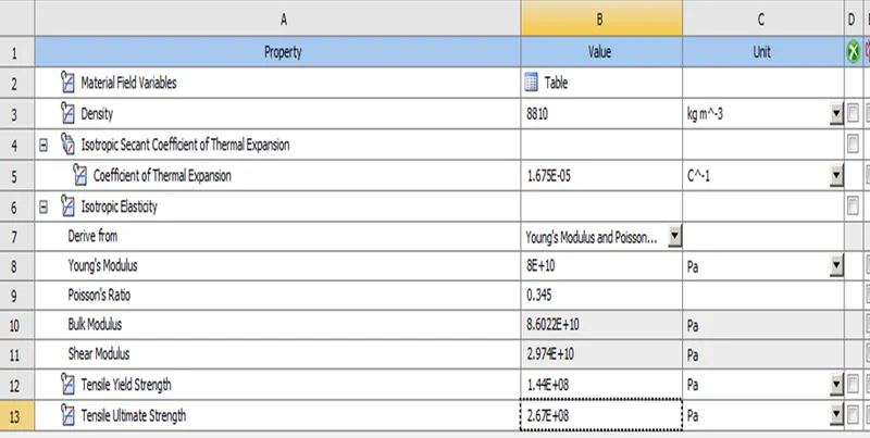
Bronze (cast) for Weld of Case 3
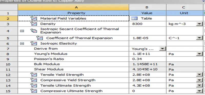
Copper Alloy for Ribs of Case 3
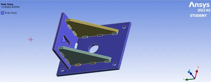
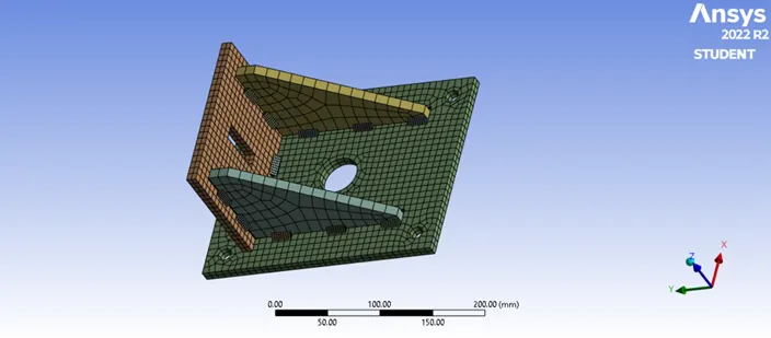
Mesh: The Body mesh size of the plates are 7 mm.
Nodes: 25090
Element: 3994
Body sizing for mesh of 7 mm of 2 plates
Meshing
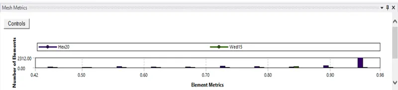
Mesh Metrics: are good as it is concentrated above 90 and are acceptable
Contact Settings:
Each weld is connected to the rib or plate (small or big) and are bonded. Selection is made accordingly.
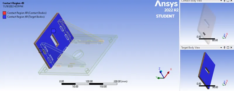
The Small and Large plate are in Frictional Contact with the 2 ribs. The Coefficient of Friction is taken as 0.2.
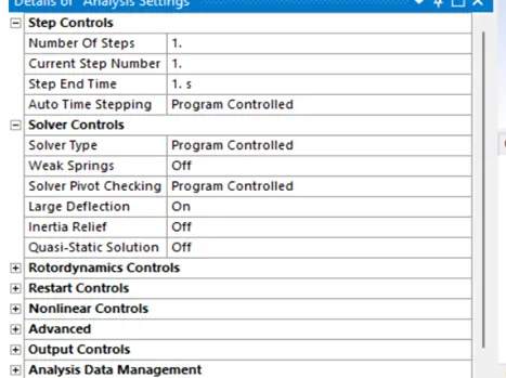
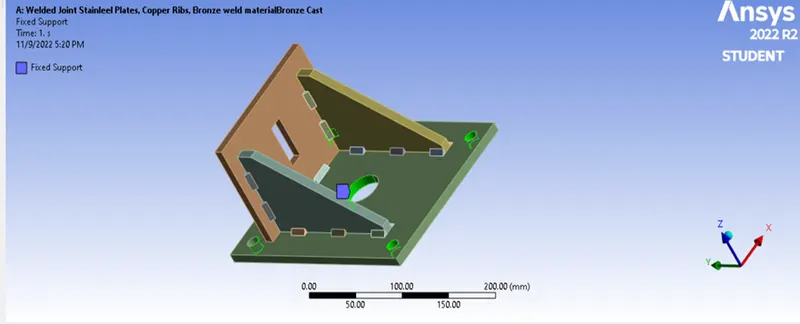
Analysis Settings: The Large Deflection is activated (on). The fixed support are the 5 holes in Large Plate. The load of 15000 KN is applied in Y direction.
Fixed Support:
Force:
Solutions:
- Directional Deformation
- Equivalent Strain
- Equivalent Stress for weld joint having maximum stresses
- Safety Factor
- Weld Stress
Results:
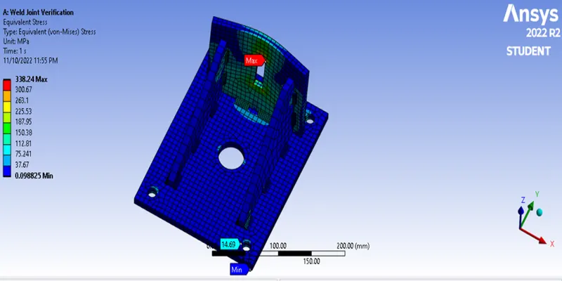
- Case 1 (Maximum Stress for weld simulation shown separately for comparison)
Equivalent Stress
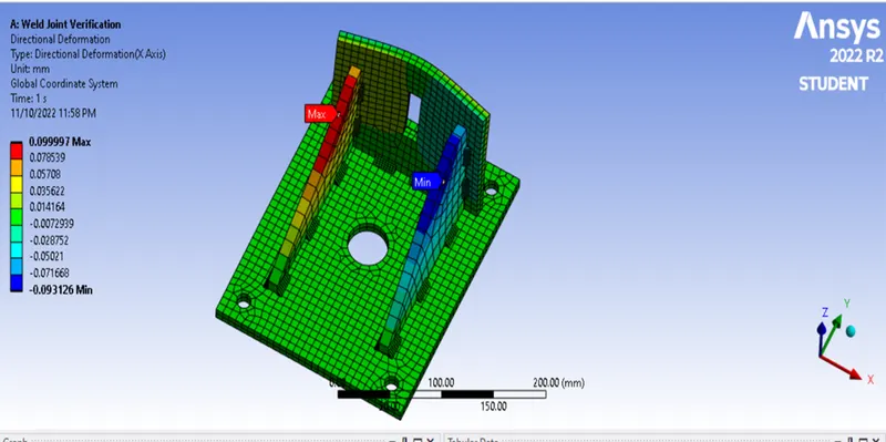
Case 1 (Directional Deformation)
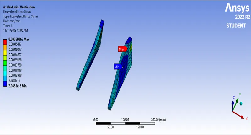
Case 1 (Elastic Strain Ribs)
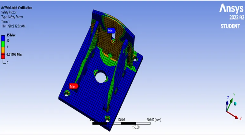
Case 1 Safety Factor
Case 1 Pressure
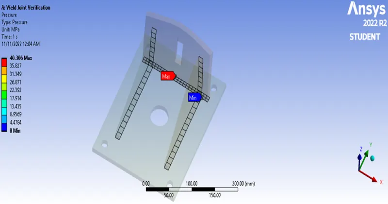
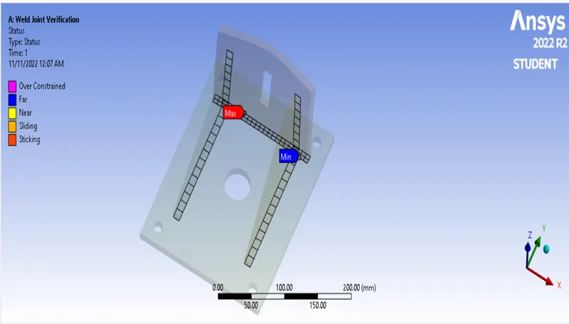
Case 1 Status
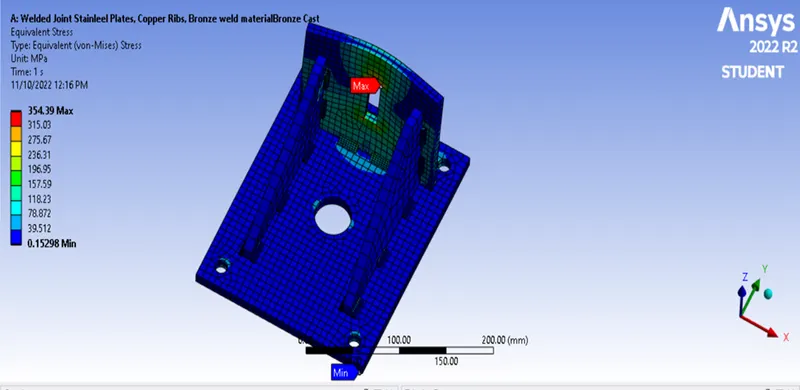
Case 2
Equivalent Stress-All
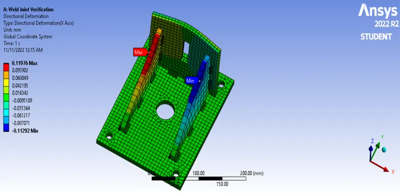
Case 2: Directional Deformation
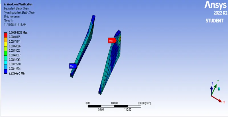
Case 2: Equivalent Strain: (for ribs)
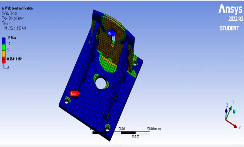
Case 2 Safety Factor
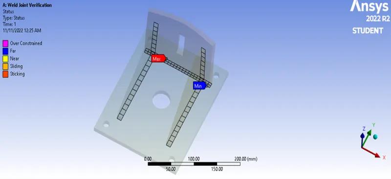
Case 2 Contact Status
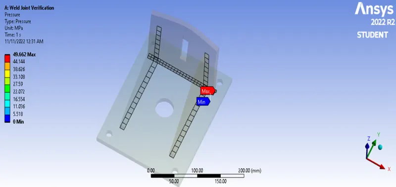
Case 2 Contact Pressure
Case 3
Equivalent Stress
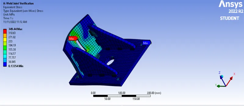
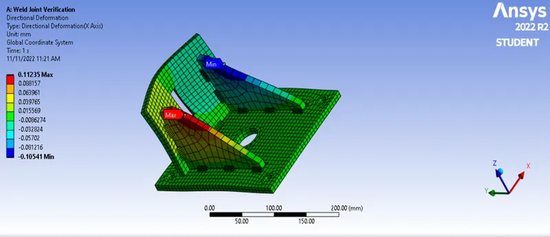
Case 3 Directional Deformation
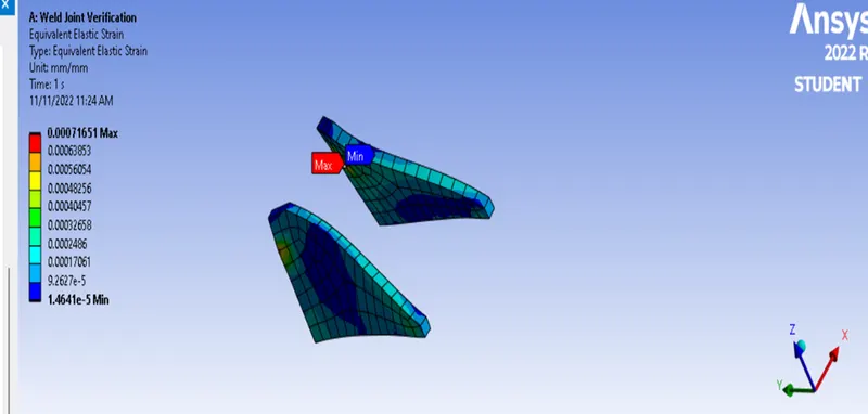
Case 3 Elastic Strain- Ribs
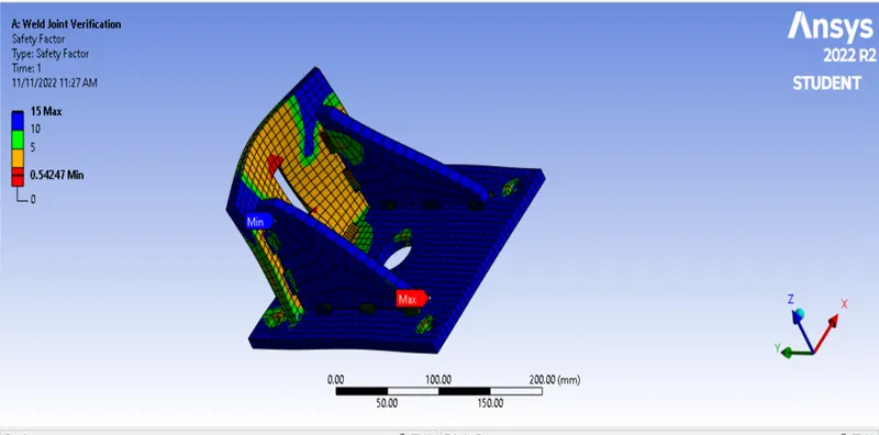
Case 3 Safety Factor
Case 3 Status
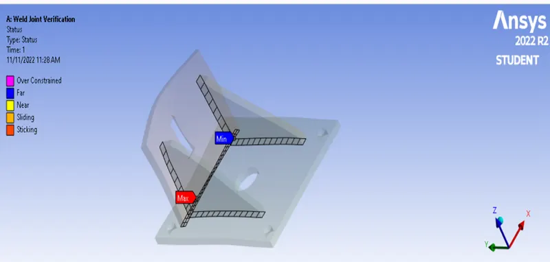
Case 3 Pressure
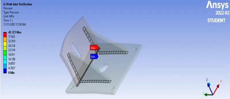
Locations of Highest weld stresses in all cases
Maximum Stress for Welds: (Showing maximum and minimum stress zone): Case 1
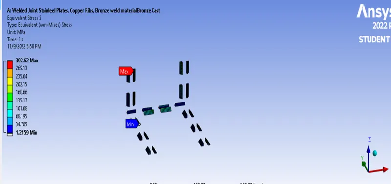
Maximum Stress for Welds: (Showing maximum and minimum stress zone): Case 2
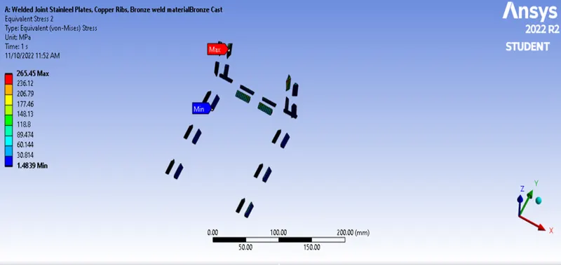
Maximum Stress for Welds: (Showing maximum and minimum stress zone): Case 3
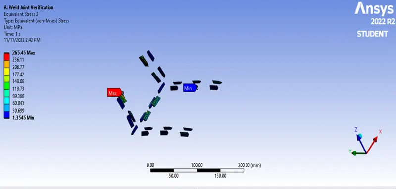
It is seen that in all cases the weld locations for highest stresses are at same location.
Conclusion:
- The Directional Deformation, equivalent Strain, highest equivalent Stress in each case is as per table below. (This is from Parametric chart). The material properties are given below also to compare the stresses.
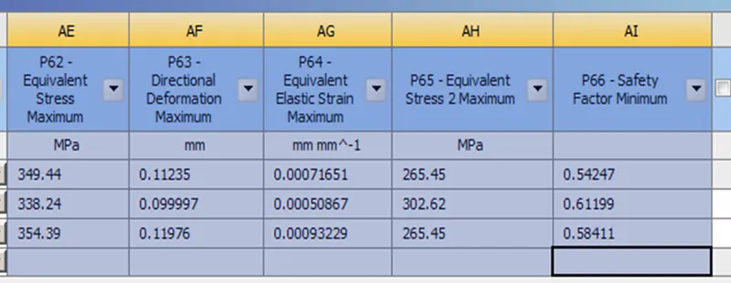
Row 1 Case 3
Row 2 Case 1
Row 3 Case 2
|
Weld Metal |
Rib Material |
Equivalent Stress Max. |
Directional Deformation by set up Max. |
|
|
MPa |
mm |
|||
|
Case 1 |
Stainless Steel |
338.24 |
0.099997 |
|
|
Case 2 |
Aluminium Alloy |
Aluminium Alloy (high strength wrought) |
354.39 |
0.119765 |
|
Case 3 |
Bronze cast |
Copper Alloy |
349.44 |
0.11235 |
|
Equivalent Elastic Strain by set up (mm mm^-1) |
Equivalent Stress in weld Max. MPa |
Safety Factor Min. |
|
|
Case 1 |
0.00050867 |
302.62 |
0.61199 |
|
Case 2 |
0.00093229 |
265.45 |
0.584 |
|
Case 3 |
0.00071651 |
265.45 |
0.54247 |
|
S. No. |
Material |
Youngs Modulus Pa |
Yield Strength Pa |
Tensile Strength Pa |
|
|
1 |
Stainless Steel |
1.93E+11 |
2.07E+08 |
5.86E+08 |
|
|
2 |
Aluminium Alloy |
7.10E+10 |
2.8E+08 |
3.10E+08 |
|
|
3 |
Aluminium Alloy (high Strength, wrought) |
7.38E+10 |
3.63E+08 |
4.49E+08 |
|
|
4 |
Bronze, Cast |
8.00E+10 |
1.44E+08 |
2.67E+08 |
|
|
5 |
Copper Alloy |
1.1E+11 |
2.8E+08 |
4.30E+08 |
- The weld with high stresses must be reinforced by size or length to take the load. The highest weld stresses are at same locations in all 3 cases.
- The safety factors are below 1. Safety factors have to be as per International/national standards. Therefore, in all cases the setup is unsafe.
- The maximum stress is occurring in Plate near rectangular hole. Use alternative material or set up to reduce the stress.
- The above comments are based on design in elastic zone.