Week 3 Verification of Weld Joints
Verification of Weld Joints
Objective:
Simulate three different types of welding using three different types of weld materials
Case 1. Stainless Steel. Use Stainless steel for both weldments and plates
Case 2. Aluminium Alloy (high strength, wrought) as Weldments. The plate material to be used is stainless steel
Case3. Bronze: In order to simulate "Brazing", you should be using bronze as the weld material. Assign Stainless Steel to both plates and Copper to the "Ribs".
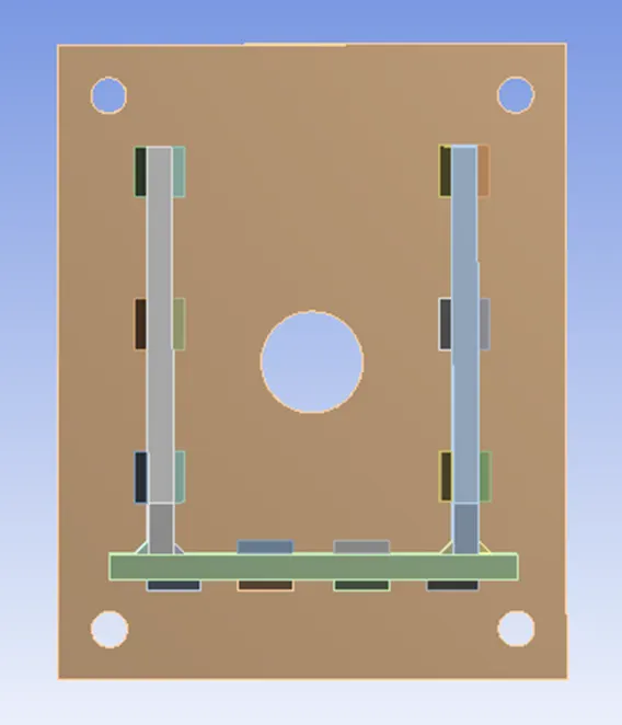
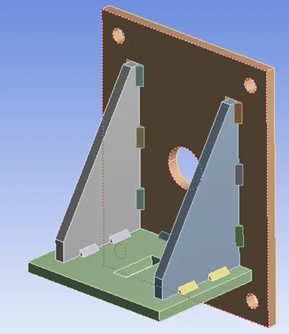
CAD Model of the Plates, Ribs and Weldments is incorporated for Analysis (Front view & Isometric view)
Material Properties have been taken from Engineering Data Sources of Ansys Workbench
|
Material Specifications for |
Density (Kgm^-3) |
Young’s Modulus [MPa] |
Bulk Modulus [MPa] |
Shear Modulus [MPa] |
Yield Strength [MPa] |
Ultimate Strength [MPa] |
|
Case I Stainless Steel |
7750 |
1.93E11 Pa or 193000 MPa |
1.693E11 Pa or 169300 MPa |
7.3664E10 Pa or 73664 MPa |
2.07E8 Pa or 207 MPa |
5.86E8 Pa or 586 MPa |
|
Case II Aluminium Alloy High Strength Wrought |
2770 |
7.38E10 Pa or 73800 MPa |
7.546E10 Pa or 75460 MPa |
2.7599E10 Pa or 27599 MPa |
3.63E8 Pa or 363 MPa |
4.49E8 Pa or 449 MPa |
|
Case III Bronze cast |
8810 |
8E10 Pa or 80000 MPa |
8.6022E10 Pa or 86022 MPa |
2.974E10 Pa or 29740 MPa |
1.44E8 Pa or 144 MPa |
2.67E8 Pa or 267 MPa |
Case 1. Stainless Steel. Using Stainless steel for both weldments and plates
Material Used: Stainless Steel for Big Plate, Small Plate, Rib1, Rib2 and Weldments together.
Connections
Contact Settings:
Initiating contact settings is crucial for the designer and end-user since the setting of contact surfaces is discretionary of the designer as to what to ignore and which to consider. Here the Plates, Ribs and Weldments are in constant contact to undergo dynamic attributes of stresses, strains and deformations as such the designer has to closely observe and predict the cognitive analytical ability to consider it as crucial for setting the contact region and ignoring other factors for efficient (i.e. Saving Time and Energy) Way of Analysing.
Contacts allowing separation (e.g. frictional contacts) are non-linear contacts. For FE models with non-linear contacts, an iterative process is involved to obtain a solution and therefore non-linear contact analyses are more computationally demanding.
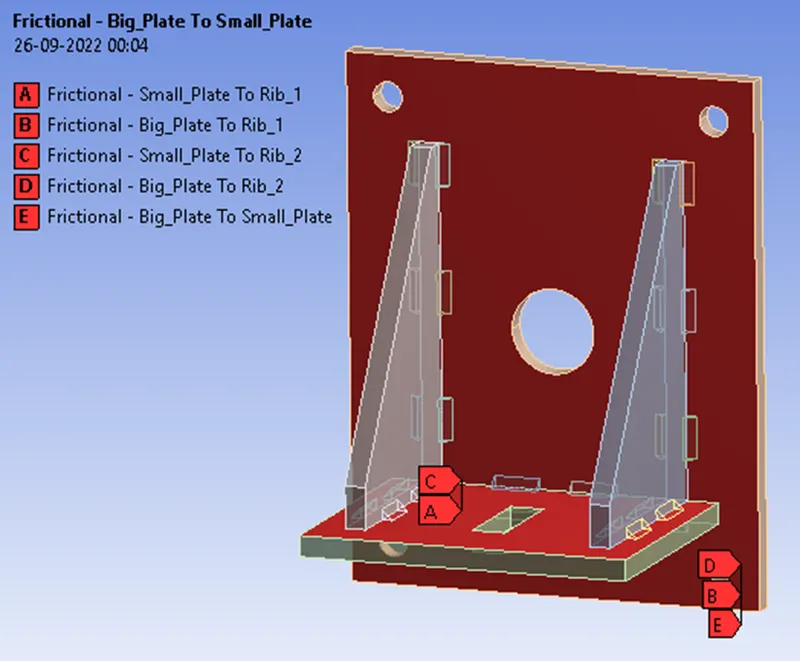
Frictional Contact - Big Plate to Small Plate, Big Plate to Rib 1, Rib 2 and Small Plate to Rib 1, Rib 2.
This state is known as “sticking.” The model defines equivalent shear stress (shear stress refers to cases where the deforming force is parallel to a surface) at which sliding on the geometry begins as a fraction of the contact pressure. Once the shear stress is exceeded, the two geometries will slide relative to each other. The coefficient of friction can be any nonnegative value, here we take it as 0.2, Similar parameters are followed for Aluminium alloy and Bronze cast.
shear stress, the force tending to cause deformation of a material by slippage along a plane or planes parallel to the imposed stress.
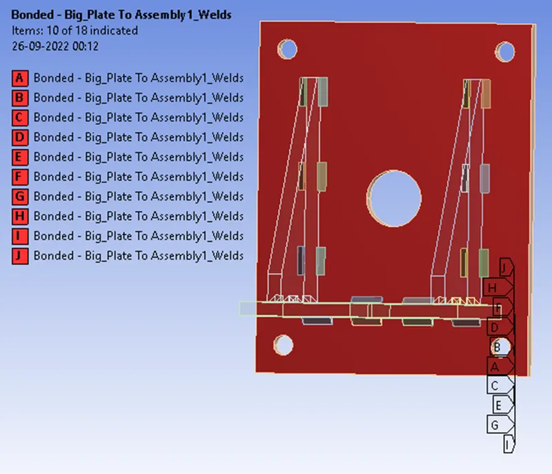
Bonded Contact – Big Plate to Weldments
The Bonded contact simulates the rigid bonding of faces to each other. If contact regions are bonded, then no sliding or separation between faces or edges is allowed. Think of the region as glued. This type of contact allows for a linear solution since the contact length/area will not change during the application of the load.
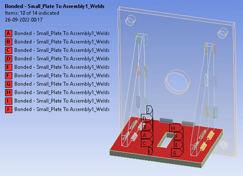
Bonded Contact – Small Plates to Weldments
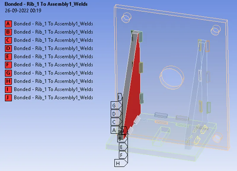
Bonded Contact – Rib 1 to Weldments
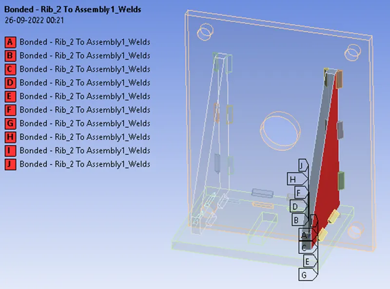
Bonded Contact – Rib 2 to Weldments
Meshing Details
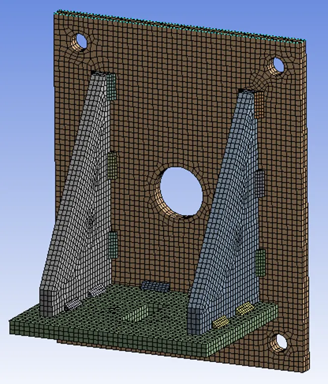
For the meshing part of default solver settings, the ANSYS solver will use the default or recommended mesh value for the model. In this case, since the model looks linear with less cross-section take the element size as 4mm. Reducing the element size at the contact surfaces is of much concern for us to achieve precise simulation results for our challenge. For Aluminium alloy and Bronze Cast material different Meshing sizes are followed.
Body Sizing for 2 bodies i.e. Big Plate & Small Plate and Ribs 1 &2 at 3mm Element Size
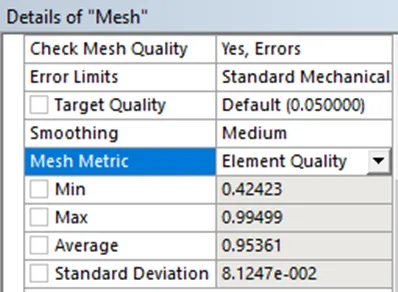
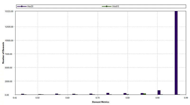
Mesh Metric:
Element Quality
The Element quality option provides a composite quality metric that ranges between 0 and 1 and this metric is based on the ratio of the volume (or area) to the square of the edge length.
So, a Value of 1 indicates a perfect cube or square or triangle or hexagon or quad while a Value of 0 indicates that the element has a zero or negative volume
Boundary Conditions
Analysis settings:
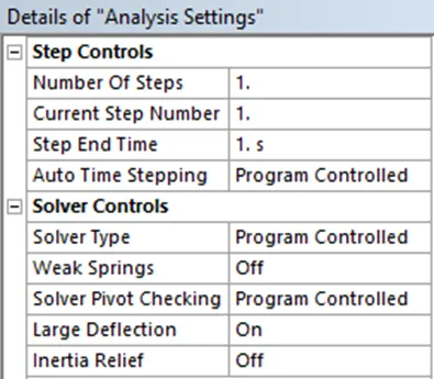
The Time Step controls of Analysis settings are crucial for Convergence of Force and Criterion values /curves as this helps the solver converge without any issues. Since we are using one step for the analysis just ignore step controls and enable Large Deflection as ON.
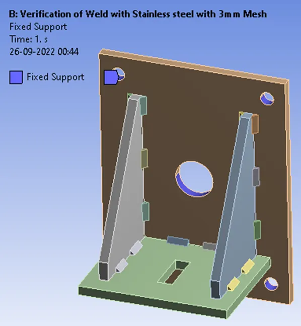
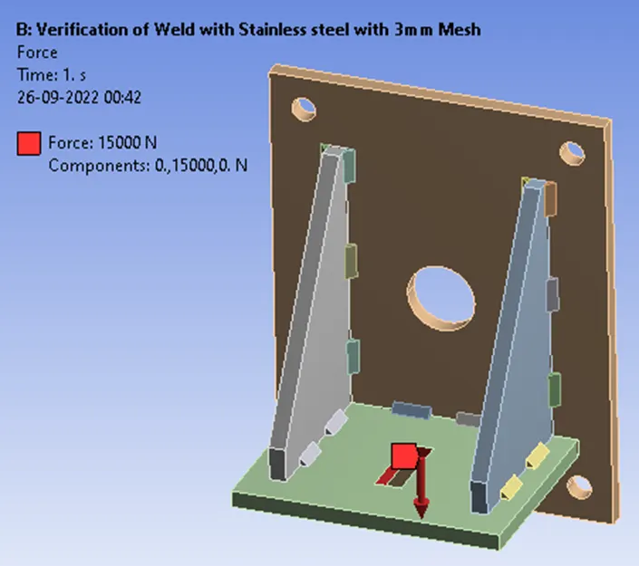
Fixed Support at Big Plate
Force at Small Plate
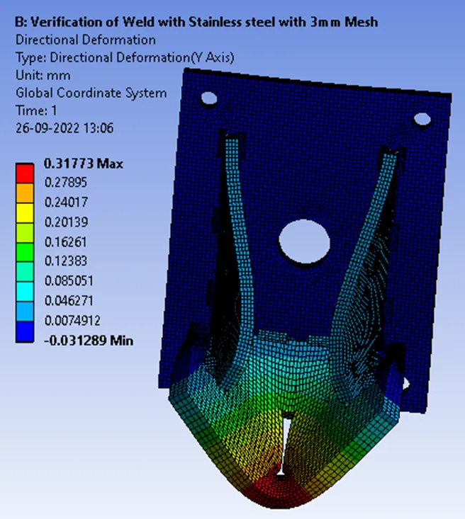
Simulation Results for Stainless Steel
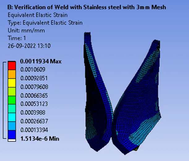
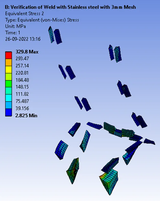
The Simulation results represented here are not on the true scale but on the exaggerated scale of 6.3e+002 (5x Auto)
Directional Deformation
Equivalent Elastic Strain
Equivalent Stress in Weld Joints for Stainless steel
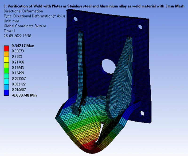
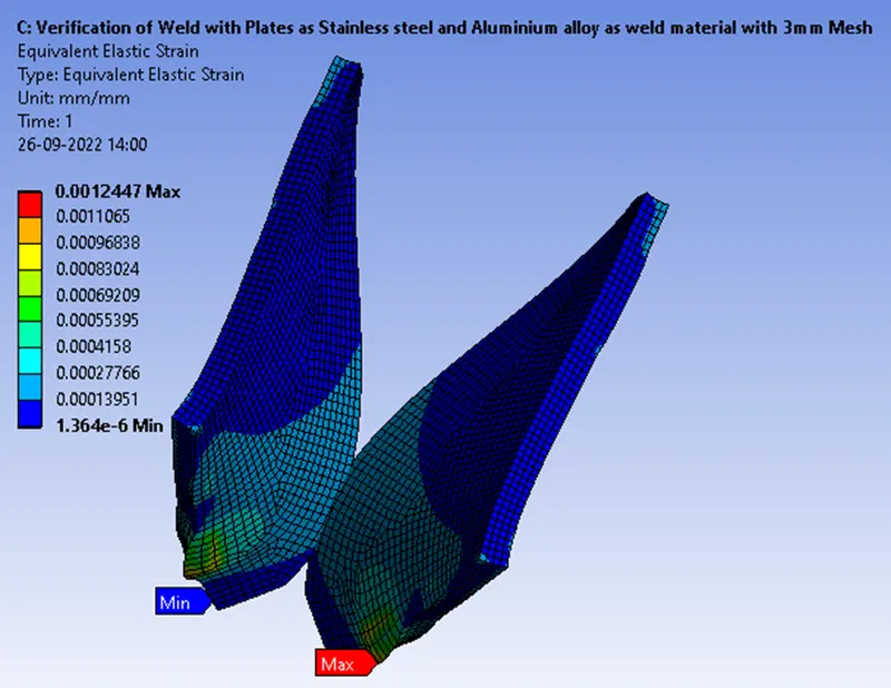
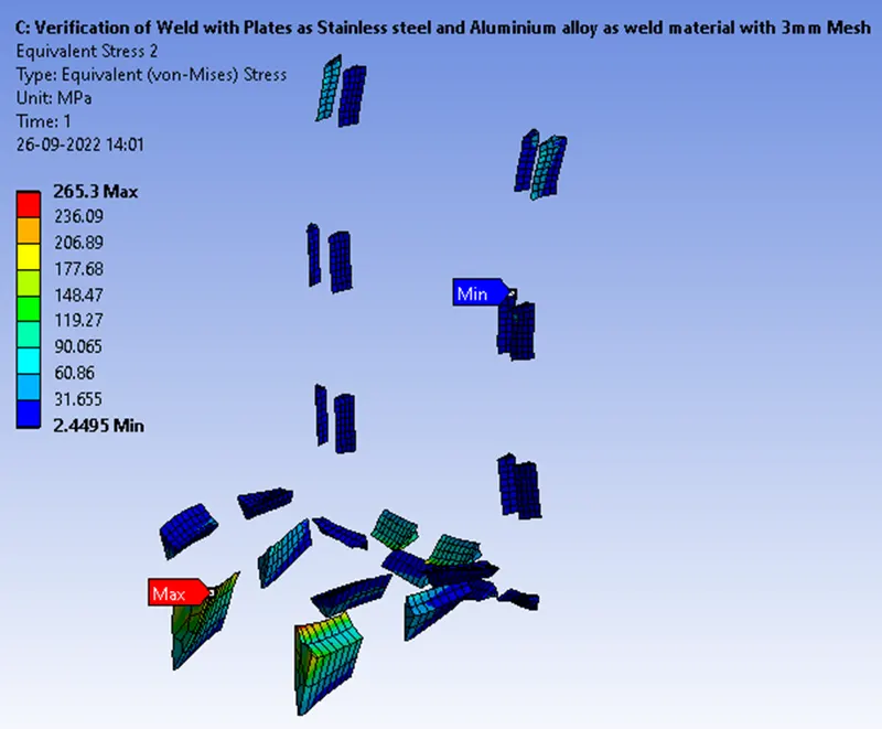
Simulation Results for Aluminium alloy (high strength, wrought)
The Simulation results represented here are not on the true scale but on the exaggerated scale of 2.5e+002 (5x Auto)
Directional Deformation
Equivalent Elastic Strain
Equivalent Stress in Weld Joints for Aluminium alloy
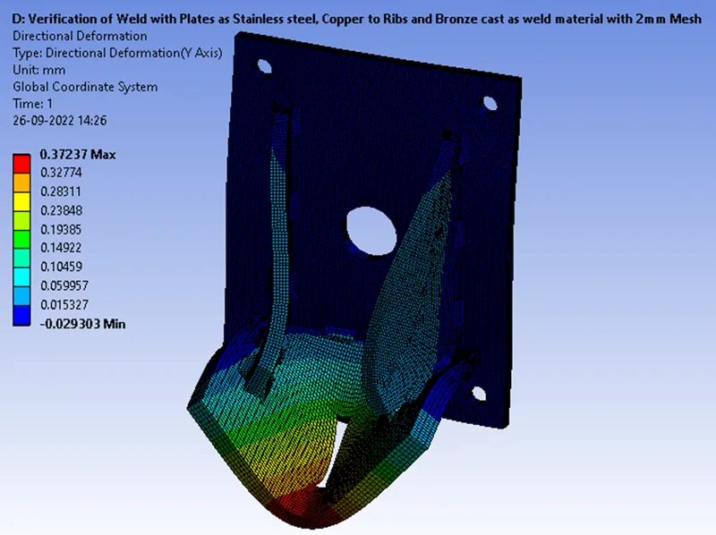
Simulation Results for Bronze cast
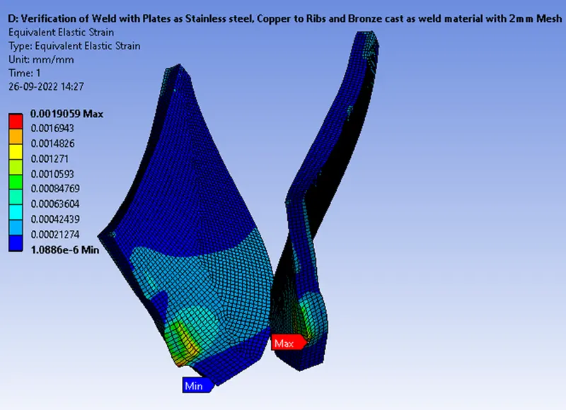
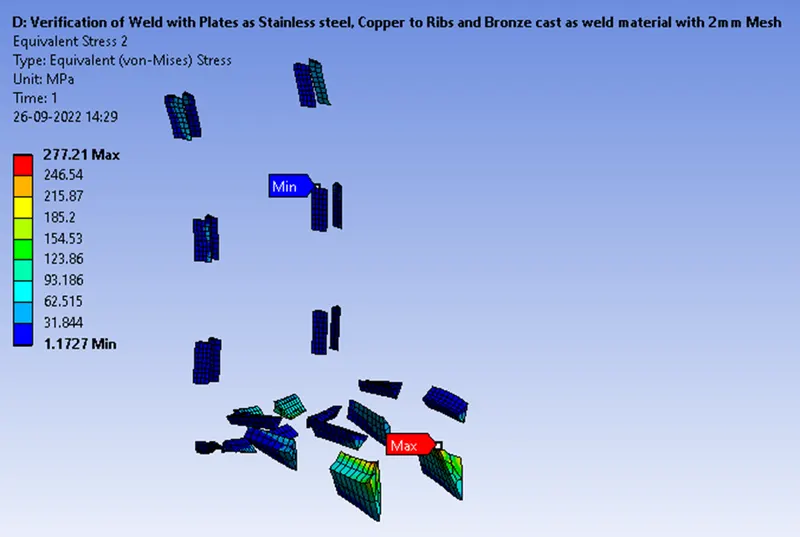
The Simulation results represented here are not on a true scale but on the exaggerated scale of 2.3e+002 (5x Auto)
Directional Deformation
Equivalent Elastic Strain
Equivalent Stress in Weld Joints for Bronze cast
Concluding Result
|
Analysing Cases for |
Directional Deformation on Plates at Y-Axis (mm) Max |
Equivalent Stress in Weldments [Pa] Max |
Equivalent Elastic Strain on Ribs [Pa] Max |
|
Case I Stainless Steel at 3mm Mesh Size |
0.31773 |
329.8 |
0.0011934 |
|
Case II Aluminium Alloy (High strength Wrought) at 3mm Mesh Size |
0.34217 |
265.3 |
0.0012447 |
|
Case III Bronze cast at 2mm Mesh size |
0.37237 |
277.21 |
0.0019059 |
From the above-tabulated results, the weld joint that experiences the highest equivalent stress on Stainless steel Weldment comparatively with others and the least is the Aluminium alloy.