Week 3 Verification of Weld Joints
Verification of Weld Joints
OBJECTIVE
To simulate and analyze the welding of plates and ribs using a particular weld material. The work has been extended by investigating case by case. The cases are as follows.
Case 1: Stainless steel as plates, ribs and weld material.
Case 2: Stainless steel as plates, ribs and Aluminium alloy as weld material.
Case 3: Stainless steel as plates, copper as ribs and bronze as weld material.
METHODOLOGY
The geometry with plates, rib and weld joints was imported and checked in Spaceclaim for any uncertainties. The bodies were rechecked for any abnormalities in spaceclaim and verified that the geometry was free of abnormalities. For case 1, all the plates, ribs and welds were of stainless steel. For case 2, plates and ribs were of stainless steel and the weld was assigned of aluminium alloy. For case 3, plates of stainless steel, ribs of copper and weld material of bronze were assigned. The material properties of stainless steel, aluminium alloy, bronze and copper are provided in Fig. 1, Fig. 2, Fig.3 and Fig.4 respectively. The geometry is shown in Fig. 5. The contact between the weldment to the ribs and weldment to the plates was defined as the ‘Bonded’ type. The contact between the big plate and small plate, big plates to ribs and small plates to ribs was defined as ‘frictional’ with a frictional coefficient of 0.2. The entire bodies were meshed using the default size and the plates were refined with a 7 mm element size. The total nodes and elements were 24913 and 3976 respectively (Fig. 6). The analysis consists of only one step. The large deflection was turned on. The inner faces of the holes which would be mounted to the wall are fixed in all degrees of freedom. A vertical force of 15,000 N was provided by selecting the inner faces of the rectangular hole. The von mises stress of the weld joint, directional deformation along the Y direction and equivalent strain of bodies are evaluated and compared.
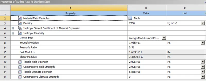
Fig. 1 Material properties of Stainless Steel
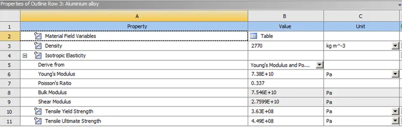
Fig. 2 Material properties of Aluminium alloy (Values are set to match with the challenge)
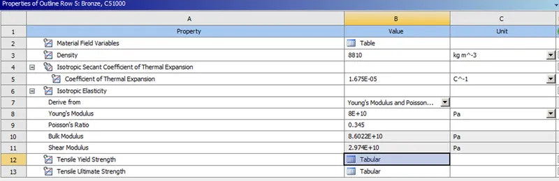
Fig. 3 Material properties of Bronze alloy (Values are set to match with the challenge)
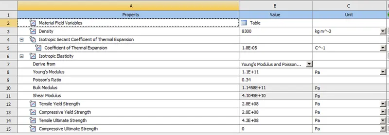
Fig. 4 Material properties of Copper alloy
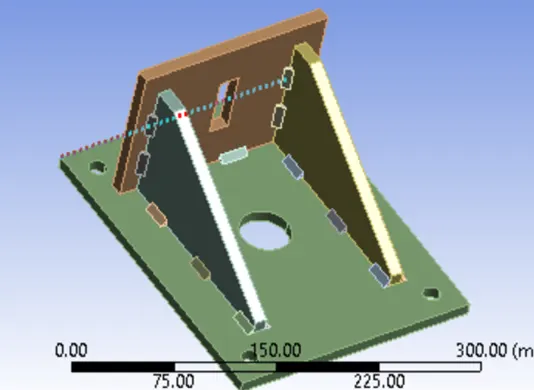
Fig. 5 Geometry of plate, rib and weldments
Fig. 6 Meshed model
RESULTS AND DISCUSSION
Three cases were investigated by assigning different materials to the welds, ribs and plates. Table 1 compares the results for the three cases. The maximum von mises stress was developed for case 1 when all the materials were stainless steel. The von mises stress was 293.94 MPa for case 1. It was also found that the maximum stress was developed as a result of minimum deformation along the Y direction and minimum equivalent strain. When the bodies resist the force, more stresses are developed within the materials. The deformation along downwards and maximum equivalent strain were 0.34987 mm and 0.0018731 respectively. Fig. 7 shows the von mises stress distribution in the welds for case 1. The maximum stress was on the weldment fixed to the rib and small plate where force was applied. The minimum stress was on the weld joining the big plate and rib. Fig.8 and Fig.9 show the directional deformation and equivalent elastic strain of all bodies. The least von mises stress was developed for case 2 where the plates and ribs were made of stainless steel and welds made of aluminium alloy. The von mises stress for case 2 was 244.2 MPa (Fig. 10). The maximum deformation and equivalent strain were 0.36472 mm (Fig. 11) and 0.0034423 (Fig. 12) respectively. In case 3 where the plates, ribs and welds were made of stainless steel, copper and bronze, the resulted von mises stress was 255.77 MPa (Fig. 13). Among all cases, maximum vertical deformation with 0.40416 mm was obtained (Fig. 14). In contrast to the case 1, there is no appreciable decrease in the von mises stress due to easiness in the deformation. It is because the materials are different in all cases and materials influence the material properties after being subjected to the forces. The equivalent strain for case 3 is 0.003202 (Fig. 15). The factor of safety in all cases was within the safe limit. The factor of safety were 0.60704, 0.5984 and 0.563 for case 1, case 2 and case 3. The maximum factor of safety was for case 1 whereas the least was for case 3.
|
Table 1 Analysis results for verification of the weld joints |
|||
|
CASE 1 |
CASE 2 |
CASE 3 |
|
|
Plate: Stainless steel Ribs: Stainless steel Weld: Stainless steel |
Plate: Stainless steel Ribs: Stainless steel Weld: Aluminium alloy |
Plate: Stainless steel Ribs: Copper Weld: Bronze |
|
|
Maximum Von Mises of welds |
293.94 MPa |
244.2 MPa |
255.77 MPa |
|
Maximum Directional deformation in Y direction of all bodies |
0.34987 mm |
0.36472 mm |
0.40416 mm |
|
Maximum Equivalent strain of bodies |
0.0018731 |
0.0034423 |
0.003202 |
|
Factor of safety |
0.60704 |
0.5984 |
0.563 |
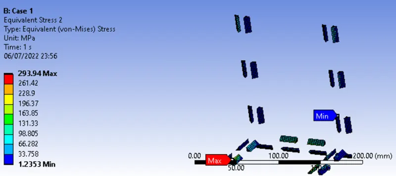
Fig. 7 Von mises stress of weldments (case 1)
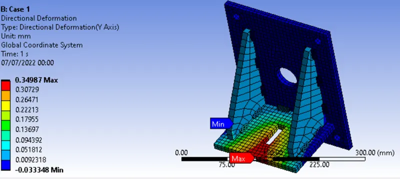
Fig. 8 Directional deformation (Case 1)
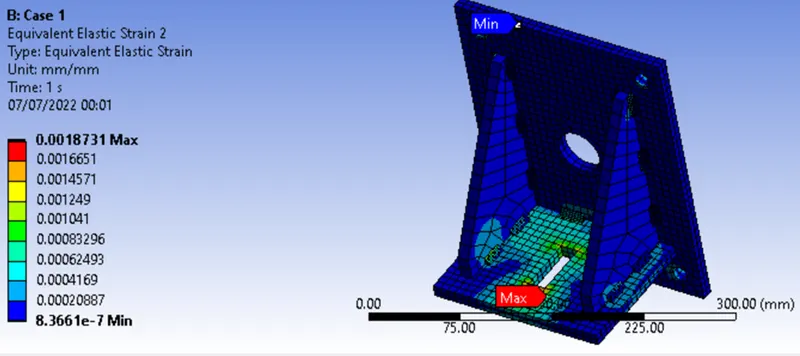
Fig. 9 Equivalent strain (Case 1)
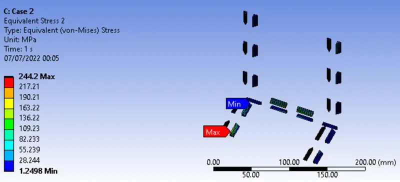
Fig. 10 Von mises stress of welds (Case 2)
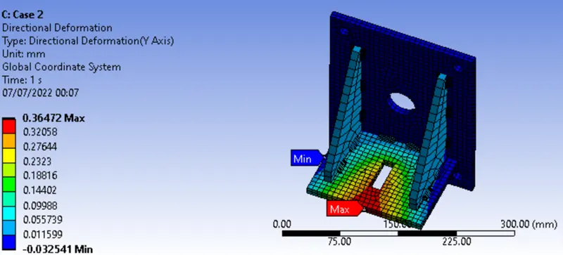
Fig.11 Directional deformation (Case 2)
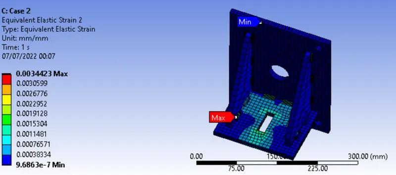
Fig. 12 Equivalent strain (Case 2)
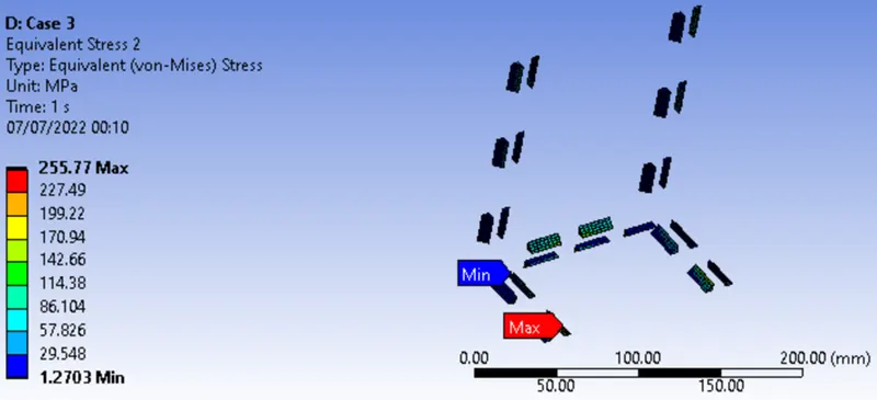
Fig. 13 Von mises stress of welds (Case 3)
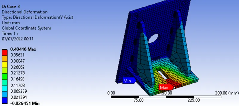
Fig.14 Directional deformation (Case 3)
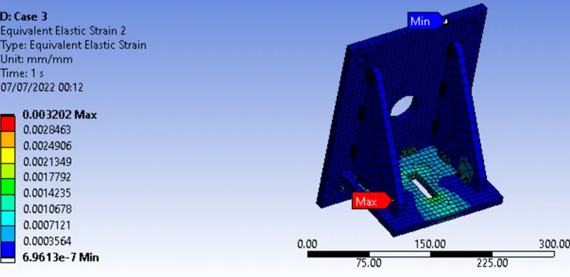
Fig. 15 Equivalent strain (Case 3)
CONCLUSION
Numerical analysis was conducted for investigating the von mises stress in welds, directional deformation along the Y direction and equivalent strain. The lower plate on which the force was acting has undergone an elastic deformation. Three cases were compared. The maximum von mises stress with 293.94 MPa was found in case 1 where all the materials were made of stainless steel. The least von mises stress in welds was seen in aluminium welds as in case 2. The maximum vertical deformation (0.40416 mm) was found in the case of brazing (Case 3). The equivalent strain of case 2 and case 3 were close to 0.003 whereas that of case 1 was 0.001. The factor of safety of all three cases was within the safe limit. i.e., the working stress was less than the allowable stress. The maximum von mises stress was observed on the weld joint joining the rib and small plate on which the force was acting in all three cases.