Week 3 Sheet metal Bending challenge
Aim
a) To perform static structural analysis for the given sheet metal bending model.
b) Interpret the results in terms of given requirements.
c) To observe effect of refining the mesh in case of Aluminum Alloy.
d) To Compare the results when coefficient of friction changes its value.
Procedure
1. Imparting the geometry
First of all ANSYS Workbench was opened and after this using right click option geometry was imported in ANSYS Workbench. The geometry for entire model is given below:
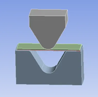
The name of these three parts have been chnaged in the given table of geometry.
2. Material Data
As per the given requirements, five materials have been added as given below:
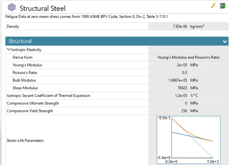
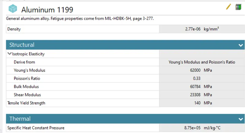
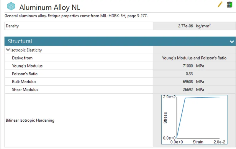
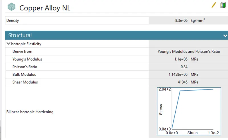
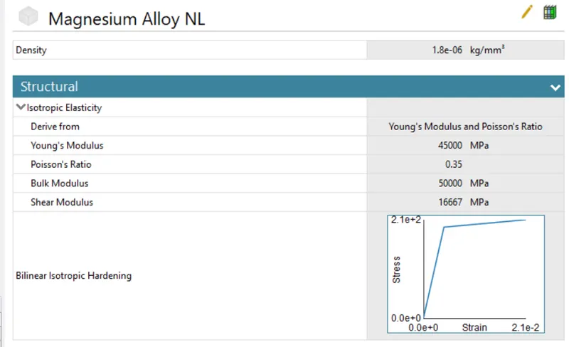
The material was changed only for sheet and the punch and die material remained same.
3. Connections
As per the figure given below, the following connections were established:
3.1 Punch to sheet
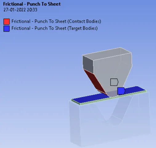
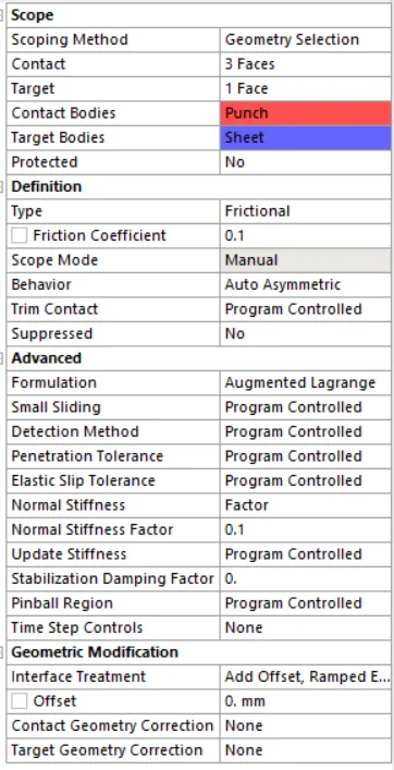
As shown in the above figure, lower all surfaces of punch were selected as the contact surfaces and the upper surface of the sheet was selected as target surface because the punch has to penetrate in the sheet surface. The type of contact was selected as frictional with coefficient of friction value as 0.1. Behaviour was elected as autosymmetric and augmented lagrange was elected as formulation. Normal stiffness factor was selected as 0.1.
3.2 Sheet to Die
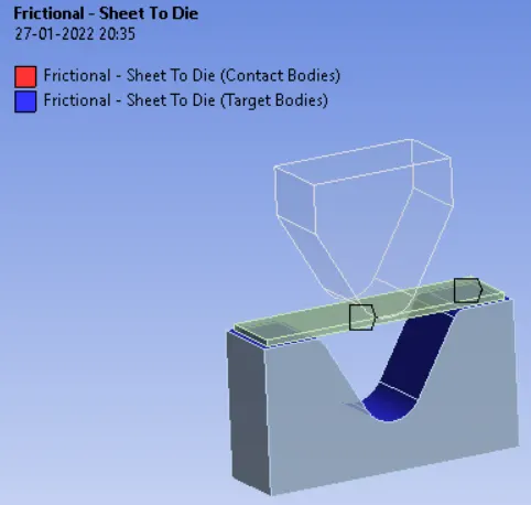
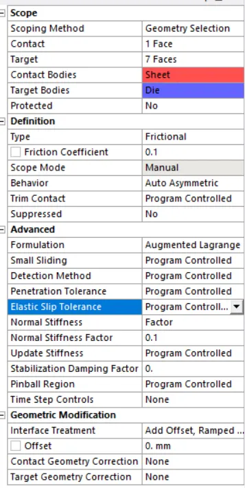
Here contact was established between sheet and die. The lower surface of sheet has been selected and similarly internal dipped surfaces of die were selected. As per the contact settings, all are same as in the punch to sheet contact.
4. Mesh Details
4.1 Body Sizing 1 Details
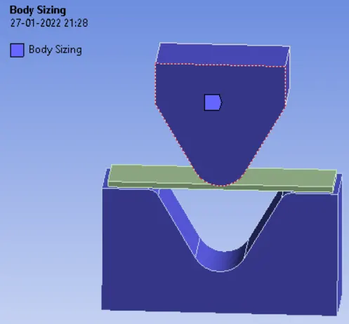
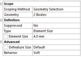
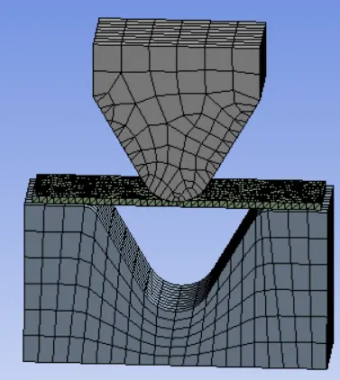
As shown in the above figure, punch and die bodies were given the mesh size of 4.0 mm and all other mesh settings were as default in ANSYS.
4.2 Body Sizing 2
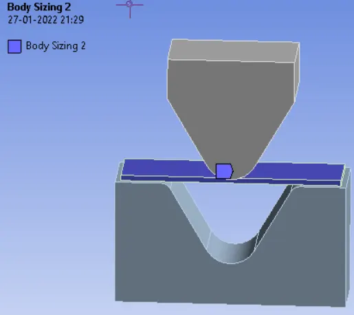
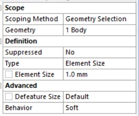
As shown above, the sheet has been given the mesh size of 1.0 mm. All other settings were remained as default. The other modification is the mesh pattern was changed as tetrahedron in sheet geometry.
4.3 Face Sizing
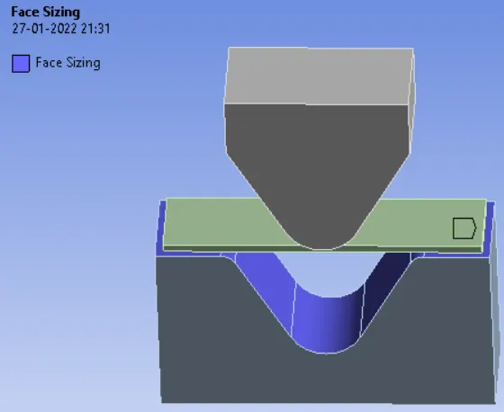
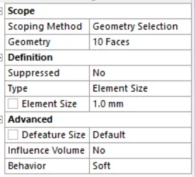
As seen in the above figure, the entire lower contact portion of punch and internal surfaces of the die those are in contact with sheet were given to the mesh size 1.0 mm.
Final mesh obtained is shown below:
5. Analysis Settings
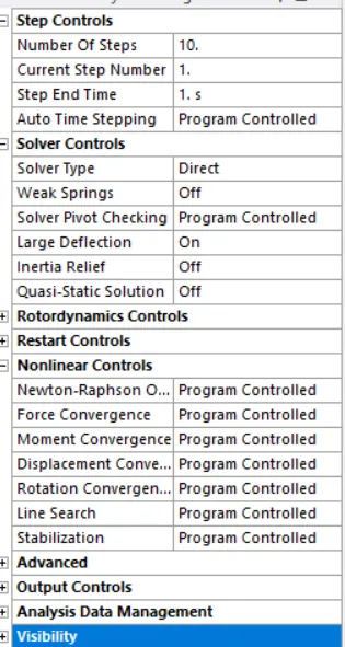
As shown above, simulation was done in the 10 steps. Auto time stepping was selected as program controlled. Large deflection was on and all other related non linear controls were declared as program controlled.
6. Load Details
6.1 Punch Displacement
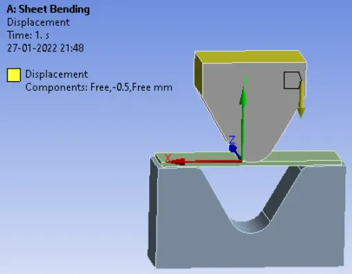
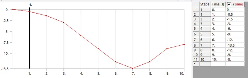
As shown above, linear displacement was given to the selected punch surfaces as in the tabular form shown above.
6.2 Sheet Displacement
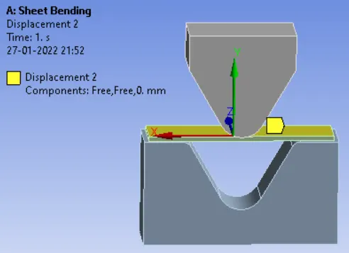
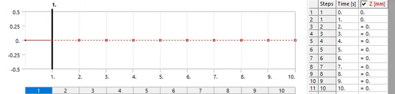
The sheet was given zero displacement in Z Direction in this simulation because it will remain fixed with respect to the Z direction.
6.3 Die Displacement
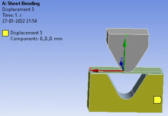
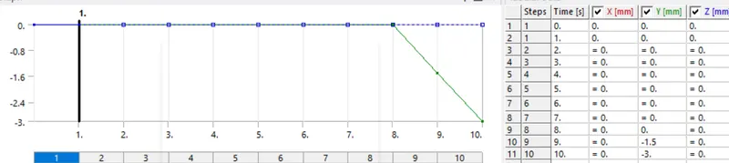
At the end of simulation, die will move in negative Y direction as per the given details in the table.
7. Results
7.1 Aluminum 1199
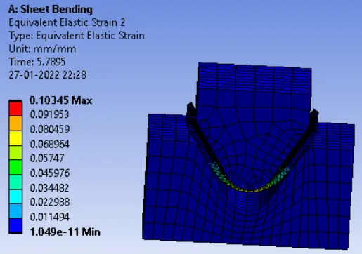
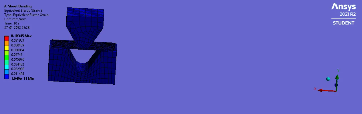
7.1.1 Equivalent Elastic Strain
7.1.2 Euivalent Stress
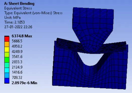
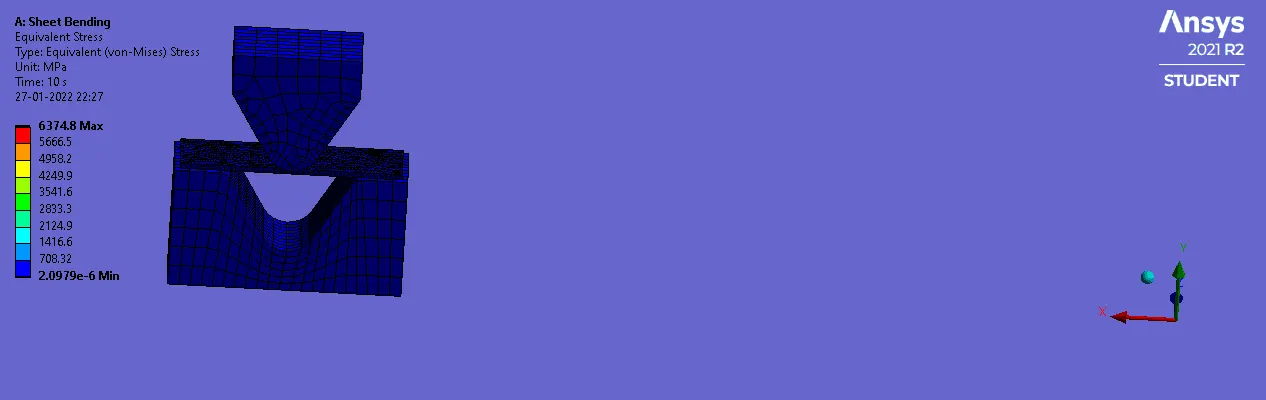
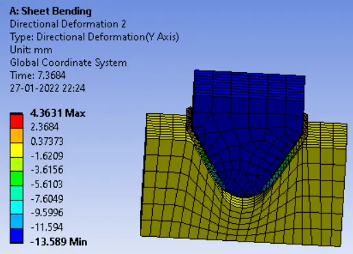
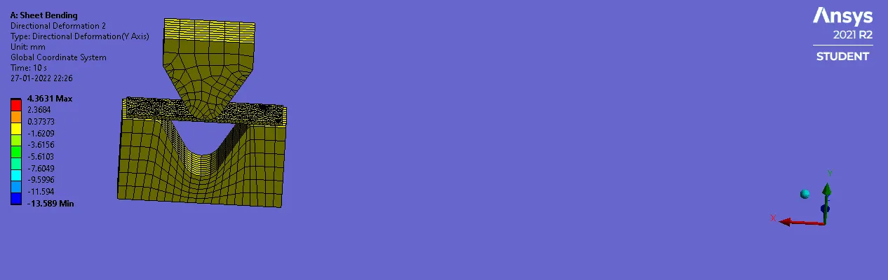
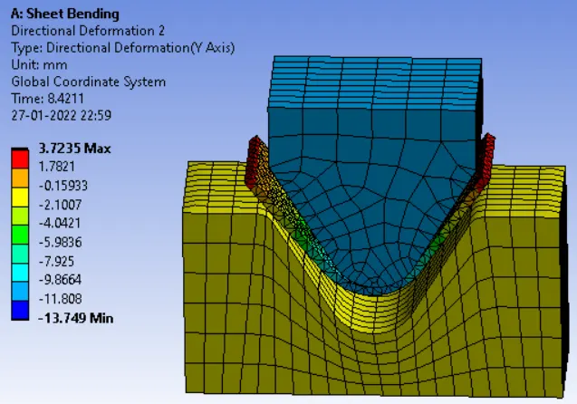
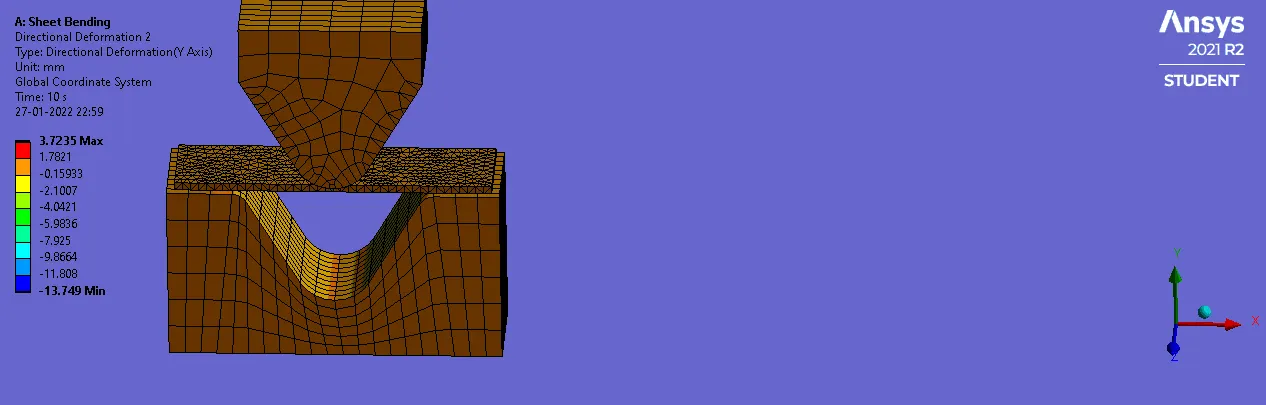
7.1.3 Directional Deformation
7.2 Copper Alloy NL
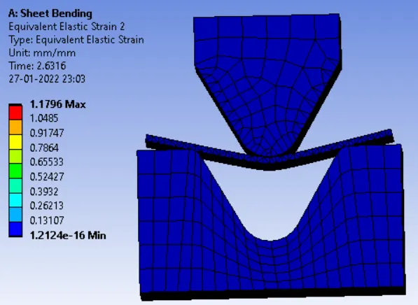
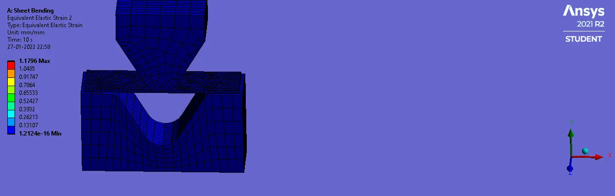
7.2.1 Equivalent Elastic Strain
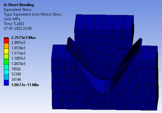
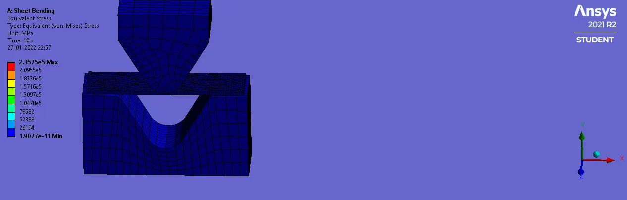
7.2.2 Equivalent stress
7.2.3 Directional Deformation
7.3 Magnesium Alloy NL
7.3.1 Equivalent Elastic Strain
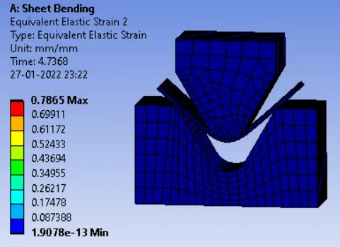
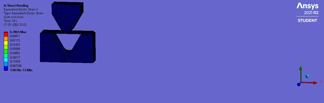
7.3.2 Equivalent Stress
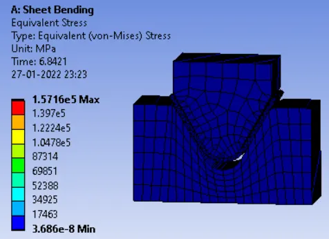
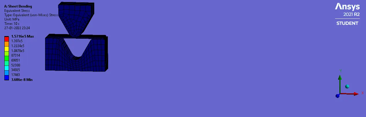
7.3.3 Directional Deformation
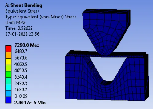
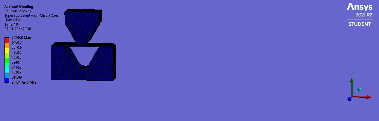
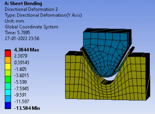
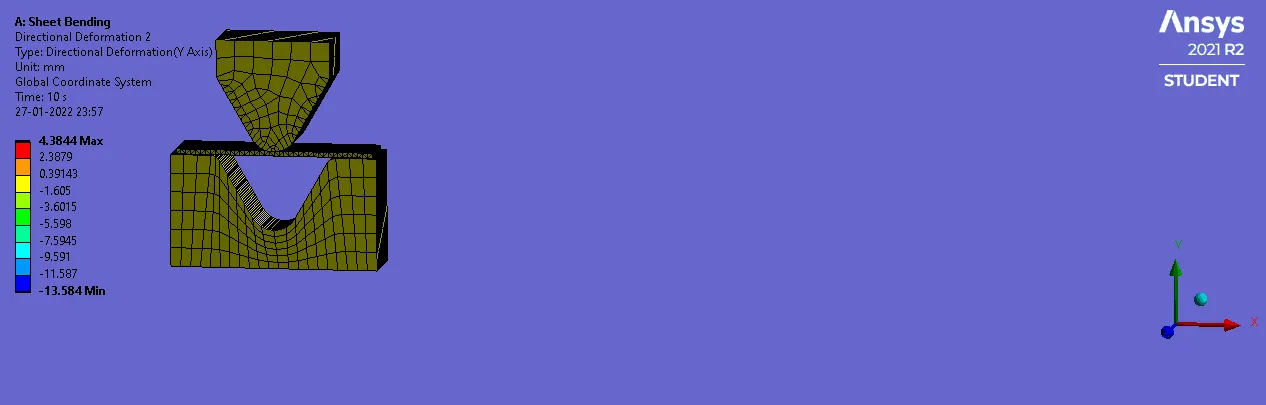
7.4 Friction Coefficient 0.19 with Aluminum Alloy
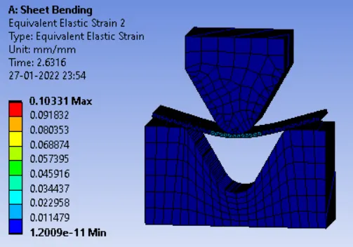
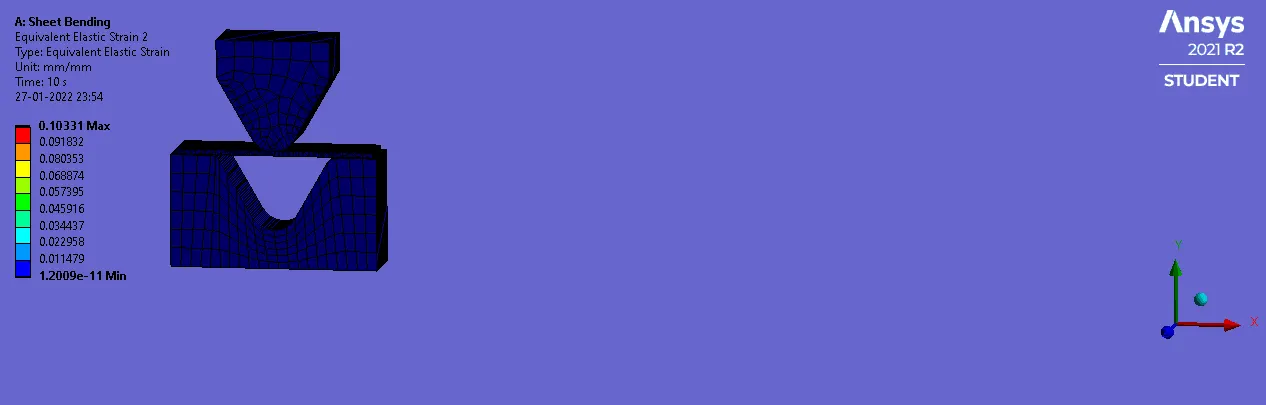
7.4.1 Equivalent Elastic Strain
7.4.2 Equivalent Stress
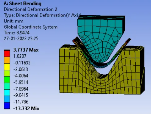
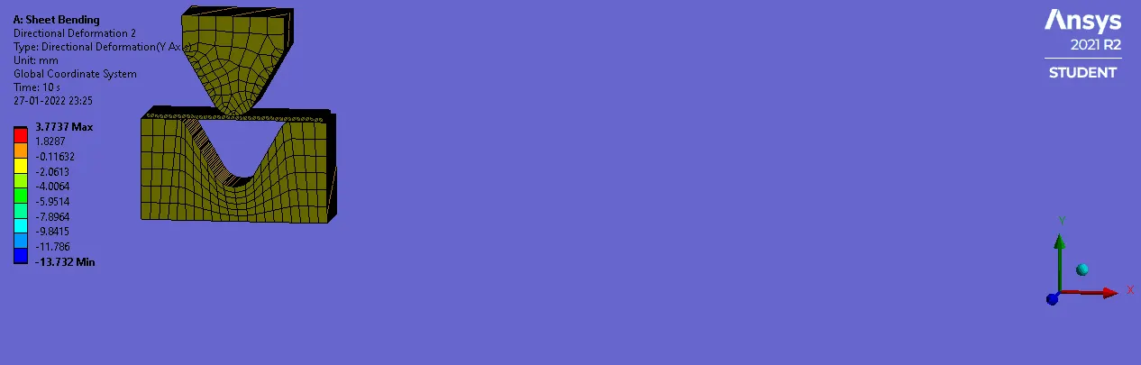
7.4.3 Directional Deformation
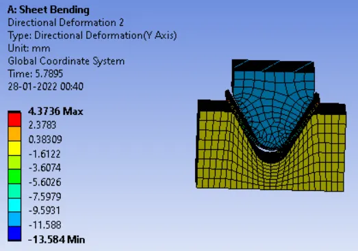
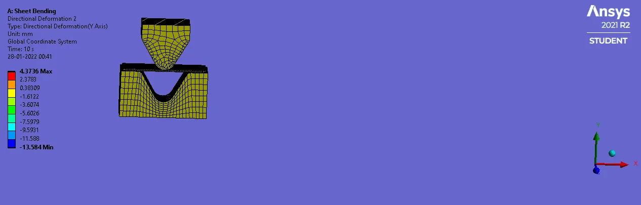
7.5 Mesh Refinement
As per the requirements, we have changed the mesh element size as given below-
Body Sizing 1 - 3.0 mm
Body Sizing 2 - 0.75 mm
Face Sizing - 0.75 mm
Material - Aluminum Alloy
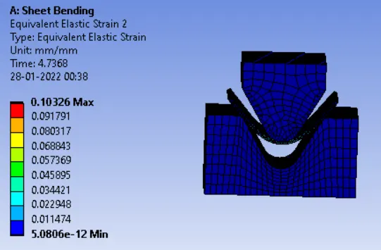
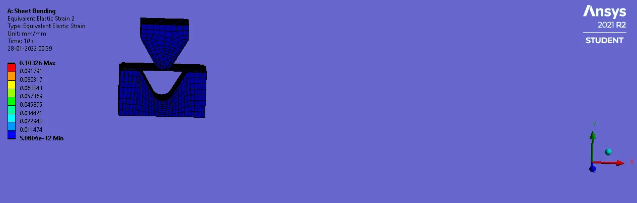
7.5.1 Equivalent Elstic Strain
7.5.2 Equivalent Stress
7.5.3 Directional Deformation
Conclusions
Case-1
a) Equivalent Elastic Strain is maximum in case of copper NL material.
b) Equivalent stress is also maximum for copper NL.
c) Direction deformation is maximum for Aluminum 1199.
Case-2
in case of friction coefficient 0.19
Max Equivalent elastic strain - 0.10331
Max equivalent stress - 7290.8 MPa
Max Directional Deformation in Y-Direction - 4.3844
Case - 3
With the mesh refinement
Max Equivalent elastic strain - 0.10326
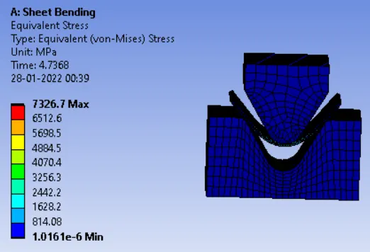
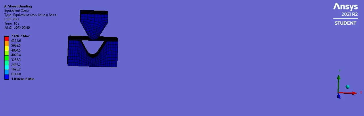
Max equivalent stress - 7326.7 MPa
Max Directional Deformation - 4.3736
If we compare case-2 and case-3, max equivalent elastic strain value decreases with mesh refinement a little bit. Max equivalent stress has been increased to a considerable value and max directional deformation is decreased a little bit.