Week 3 Sheet metal Bending challenge
CASE 1:
A) ALUMINIUM ALLOY 1199
1. Download the model from the challenge.
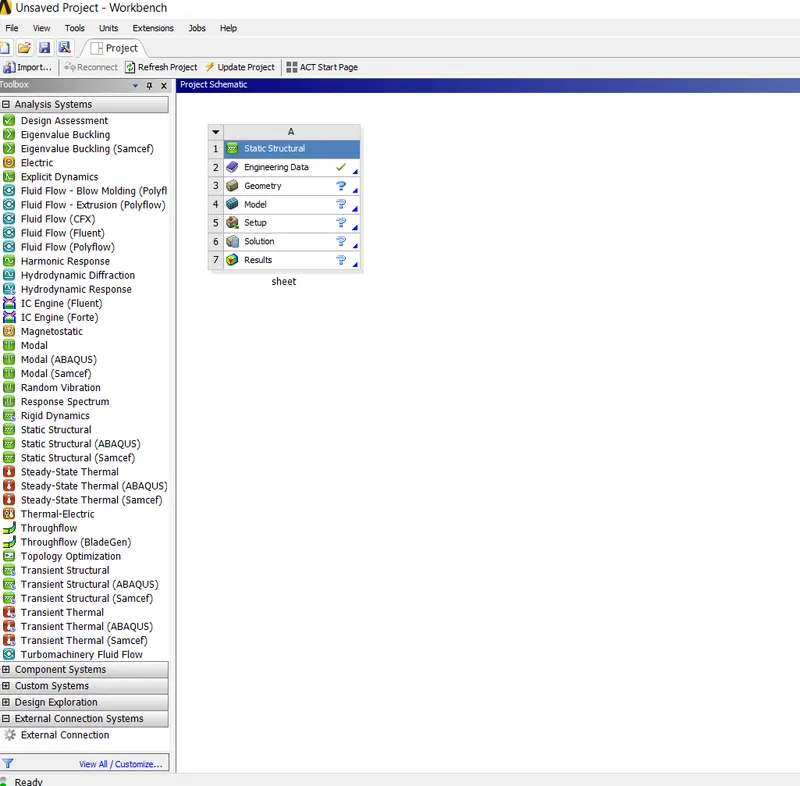
2. Open the ANSYS workbench and drag the static structure analysis.
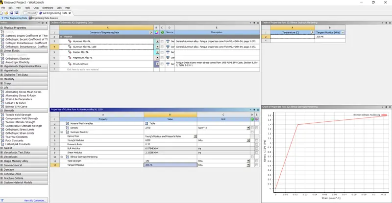
3. Double click on the engineering materials and add the aluminium nonlinear alloy and change the property as give below. And name it as aluminium 1199. And also select the magnesium and copper alloy.
4. now right click on the geometry, import the model downloaded.
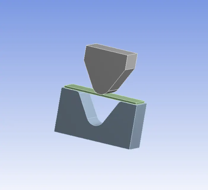
5. Now double click on the model. And check the model loaded properly or not.
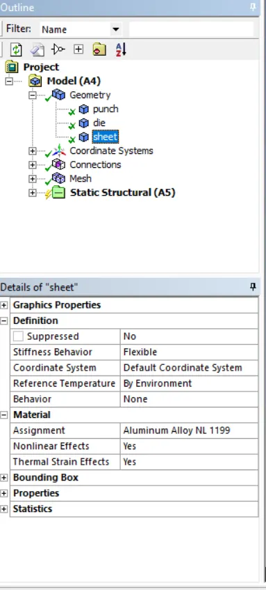
6. Now click on the geometry in the outline tree. And assign the aluminium alloy 1199 to the sheet.
7. Now click on the contacts. It shows some default contacts, delete these contacts. And provide the contacts as below.
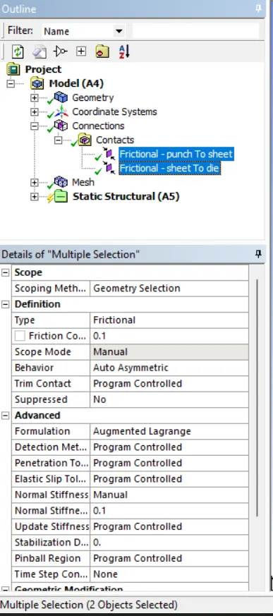
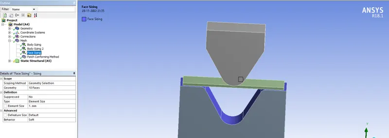
8. Click on the mesh and insert the 3 mesh tabs. First mesh the sheet with 1 mm size and 2nd mesh the contact surface with 1 mm and finally mesh the remaining part with 4 mm size.
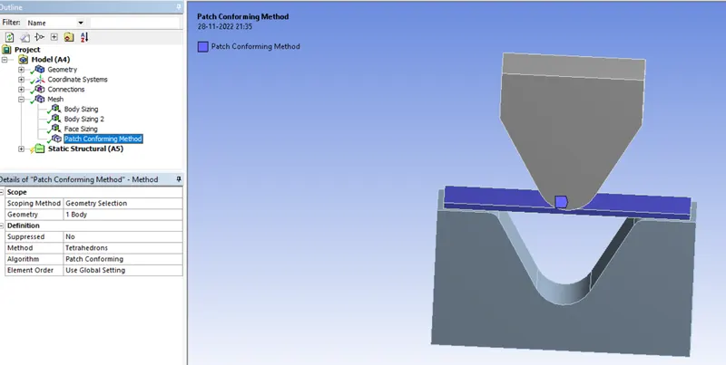
9. Insert the meshing method tab and select the sheet and give the tetrahedral meshing.
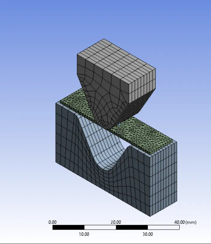
10. Now generate the mesh.
11. Now go to analysis setting and provide the 10 steps. And change the setting as mentioned below. Large deformation makes it ‘ON’.
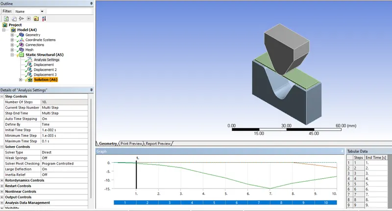
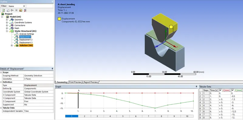
12. Insert the 3 displacement tabs. In first displacement select the top surface and give the displacement of as mentioned in the tabular form.
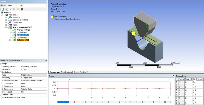
13. In the second displacement tab select the sheet and fix the z plane by provide 0 mm. so it cannot come of Z plane. And make sure that X and Y planes are free.
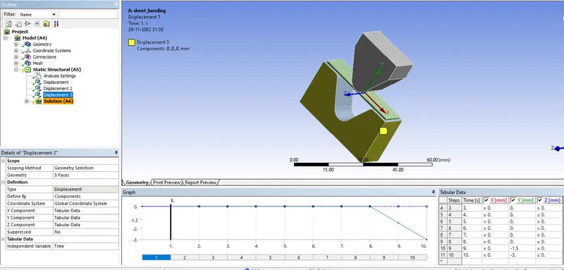
14. In the third displacement tab select the Die and give the displacement only in the last steps.
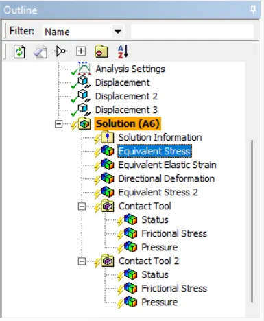
15. Now insert the solution tabs which we want check like stress, deformation in Y direction and stress only in sheet.
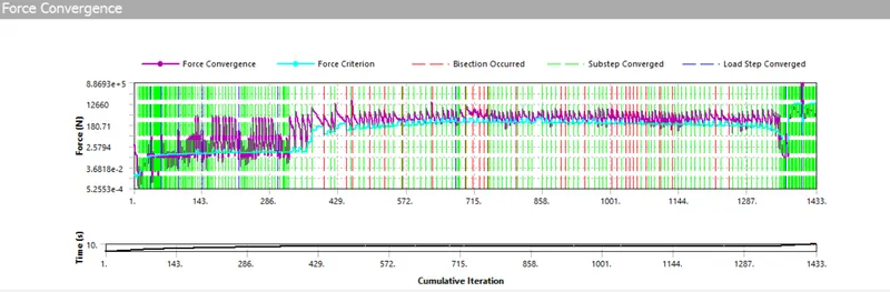
16. Now run the solution. It took nearly 35 min run. force convergence graphs shown below.
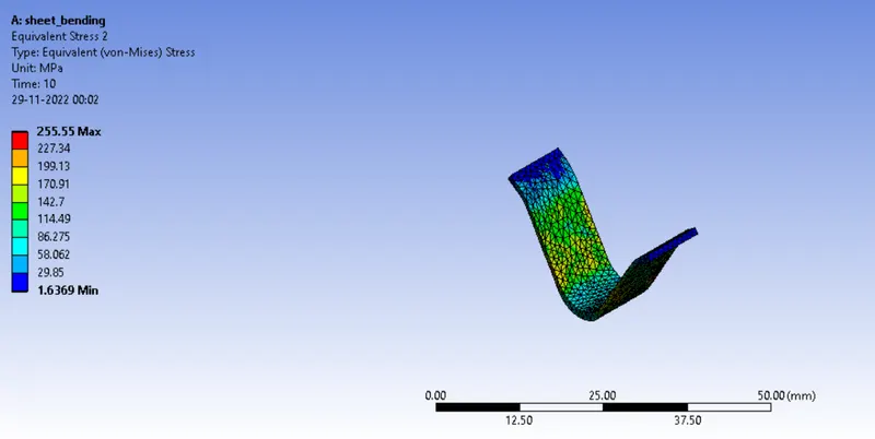
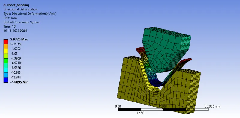
17. Now check the all solution like stress, deformation and contact tools.
B) COPPER ALLOY
1. Now duplicate the above system analysis. And double click on the model.
2. After opening the model, click on the geometry and select the sheet and change the material to copper alloy.
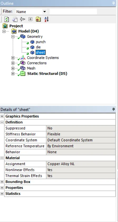
3. Now go to solution and right click on it. Select the clear the generated data.
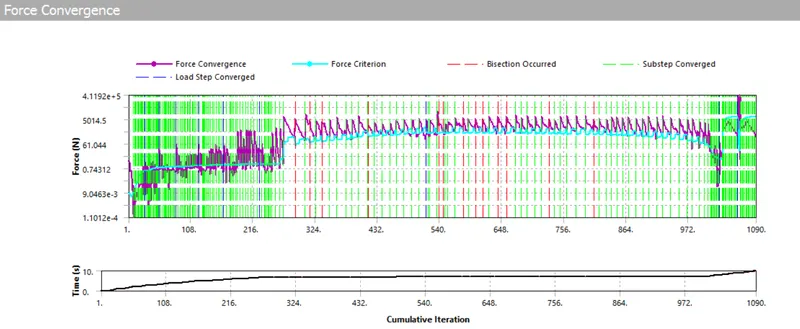
4. Now again click on the solve. force convergence graphs shown below.It will give below solution after solving.
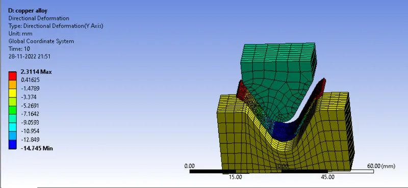
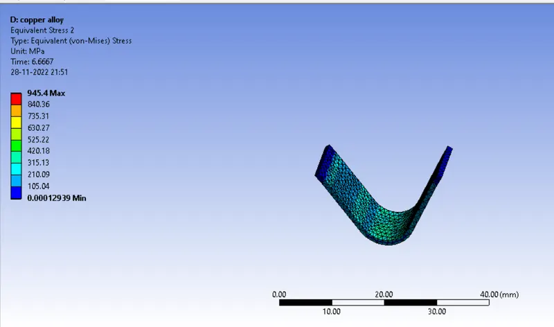
5. we can results of direction deformation in Y direction and stress in sheet.
C) MAGNESIUM ALLOY
1. Now duplicate the above system analysis. And double click on the model.
2. After opening the model, click on the geometry and select the sheet and change the material to magnesium alloy.
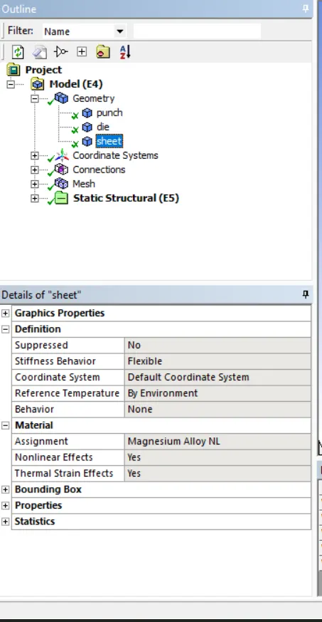
3. Now go to solution and right click on it. Select the clear the generated data.
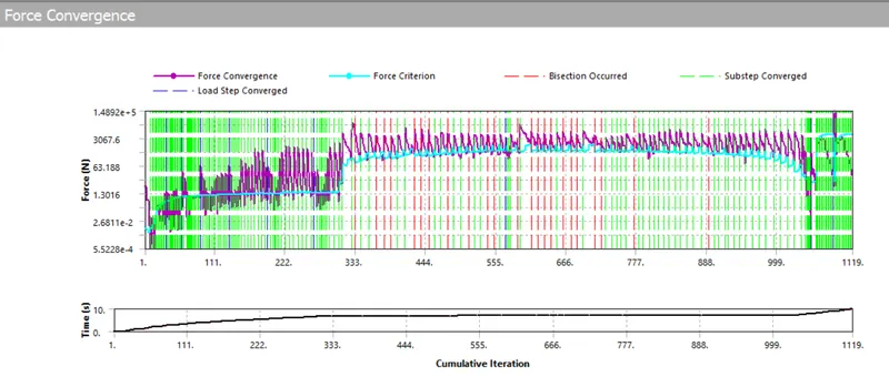
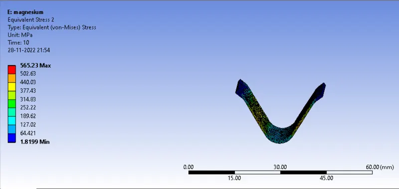
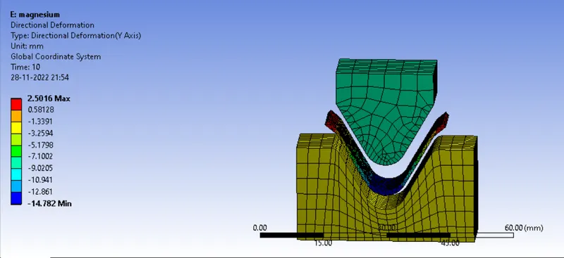
4. Now again click on the solve. force convergence graphs shown below.It will give below solution after solving.
CONCLUSION FROM CASE 1:
The stress developed in aluminium is very less compared to magnesium and copper. the stress developed in the aluminum is 255.55 MPa and in magnesium and copper is 565.23 MPa & 945.4 MPa respectively. there we conclude that aluminium deforms very easily than magnesuim and copper. but if we observe the force required to bending is very high in the case of aluminium.
CASE 2:
1. Now duplicate the above system analysis. And double click on the model.
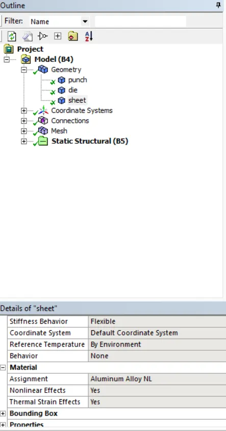
2. After opening the model, click on the geometry and select the sheet and change the material to aluminium alloy.
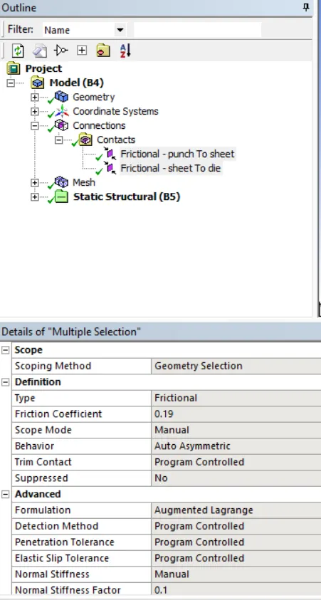
3. Now click on the contacts. Select the contacts which is already defined. And change the friction coeffient from 0.1 to 0.19.
4. Now go to solution and right click on it. Select the clear the generated data.
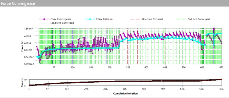
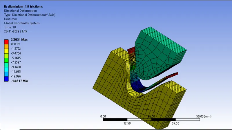
5. Now again click on the solve. force convergence graphs shown below.It will give below solution after solving.
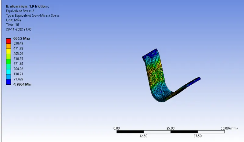
CONCLUSION FROM CASE 2:
in this case we increased the coefficient of friction so the stress developed in the sheet is maximum. the force also reduced in the bending operation due to the high friction.
CASE 3:
1. Now duplicate the above system analysis of case 2. And double click on the model.
2. After opening the model, click on the geometry and select the sheet and change the material to aluminium alloy.
3. Now click on the contacts. Select the contacts which is already defined. And change the friction coeffient from 0.19 to 0.1.
4. mesh component by reducing the mes size to 0.9 mm on sheet and die and punch contacts.
4. Now go to solution and right click on it. Select the clear the generated data.
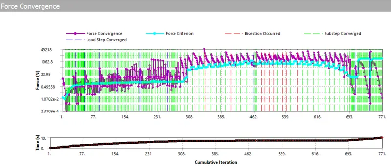
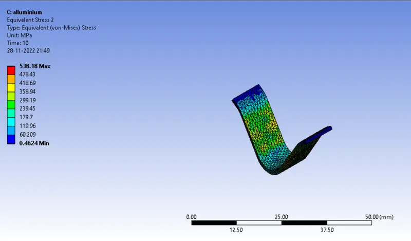
5. Now again click on the solve. force convergence graphs shown below.It will give below solution after solving.

CONCLUSION FROM CASE 3:
Refining the mesh will incease the accurate results. it have taken very long time than the other process. the results are given by case is almost same with the refining. to it always better to reduce the time to solve.