Week 3 Sheet metal Bending challenge
Aim:
To study and perform structural analysis on sheet metal with different material and frictional coefficient. A grid dependency test was also performed to optimize the element size for better accuracy.
Case 1: Aluminium Alloy 1199, Copper Alloy NL, and Magnesium Alloy NL. Finding out the Equivalent stress, Equivalent elastic strain, and Total Deformation in the Y direction and compare the results for the three materials.
Case 2: With the material as Aluminium Alloy, change the friction coefficient to 0.19 and running the analysis as mentioned in Case 1. Compare the results with the in case 1.
Case 3: Refine the mesh on the plate such that it doesn't cross the academic limit. With Aluminium alloy as material, run the analysis as in Case 1 and compare the results.
Geometry:
Bending is a manufacturing process that produces a V-shape, U-shape, or channel shape along a straight axis in ductile materials, most commonly sheet metal. Commonly used equipment includes box and pan brakes, brake presses, and other specialized machine presses. Typical products that are made like this are boxes such as electrical enclosures and rectangular ductwork.
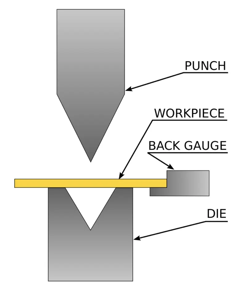
Each is defined by the relationship of the end tool position to the thickness of the material. These three are Air Bending, Bottoming, and Coining. The configuration of the tools for these three types of bending are nearly identical. A die with a long rail form tool with a radiused tip that locates the inside profile of the bend is called a punch. Punches are usually attached to the ram of the machine by clamps and move to produce the bending force. A die with a long rail form tool that has a concave or V shaped lengthwise channel that locates the outside profile of the form is called a die. Dies are usually stationary and located under the material on the bed of the machine. Note that some locations do not differentiate between the two different kinds of dies (punches and dies). The other types of bending listed use specially designed tools or machines to perform the work.
Case 1: Aluminium Alloy 1199, Copper Alloy NL, and Magnesium Alloy N. Finding out the Equivalent stress, Equivalent elastic strain, and Total Deformation in the Y direction and compare the results for the three materials.
Geometry:
The cad model is imported and viewed in SpaceClaim and checked for any errors.
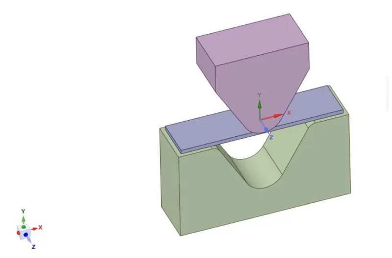
The model has a punch and dies arrangement with sheet metal as a workpiece.
Materials:
An analysis was conducted for three different materials of the sheet metals namely
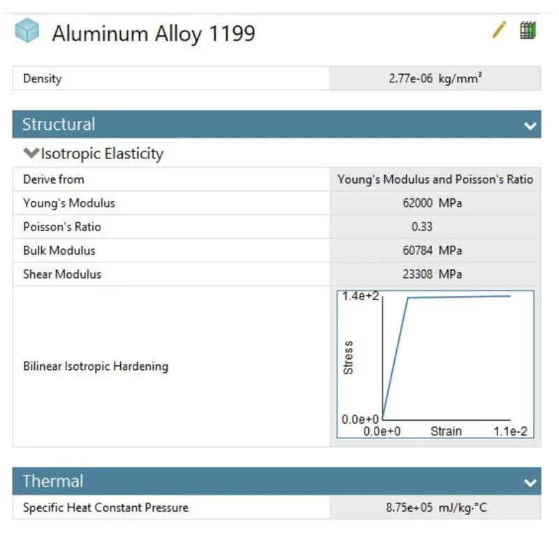
• Aluminium Alloy 1199
1199 Aluminum alloy is aluminum-based. in the "commercitlly pure" wrought family. With a minimum of 99.99% aluminum, it is the purest and least alloyed of the commercial aluminum alloys. It is soft and unsuitable for machining. At the same time, it possesses excellent corrosion resistance, electrical conductivity, and thermal conductivity.
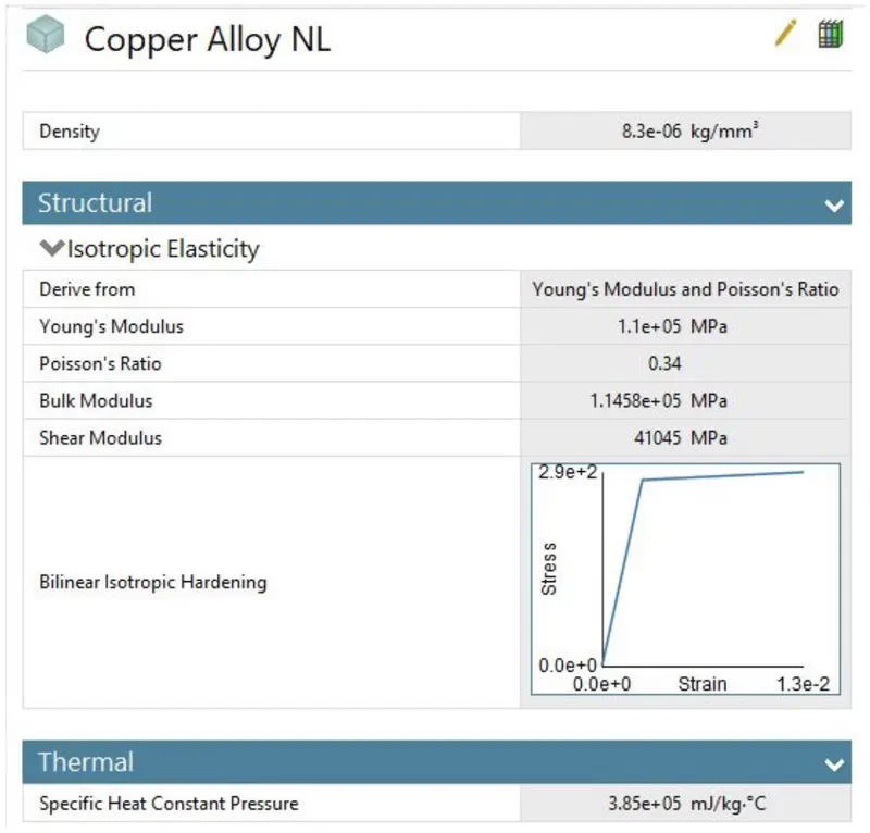
• Copper Alloy NIL
Copper alloys are metal alloys that have copper as their principal component. They have high resistance against corrosion. The best known traditional types are bronze, where tin is a significant addition, and brass, using zinc.
• Magnesium alloys NL
Magnesium alloys are mixture of magnesium with other metals(called an alloy), often aluminium, zinc, manganese, silicon, copper, rare earth, and zirconium.
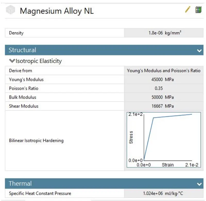
Non-Linear materials are considered to account for the regions of plastic deformation.
Meshing :
The sheet metal and faces of punch and die which comes in contact with a sheet, the sheet has alone meshed with an element size of 1mm. other parts have meshed with an element size of 4mm.
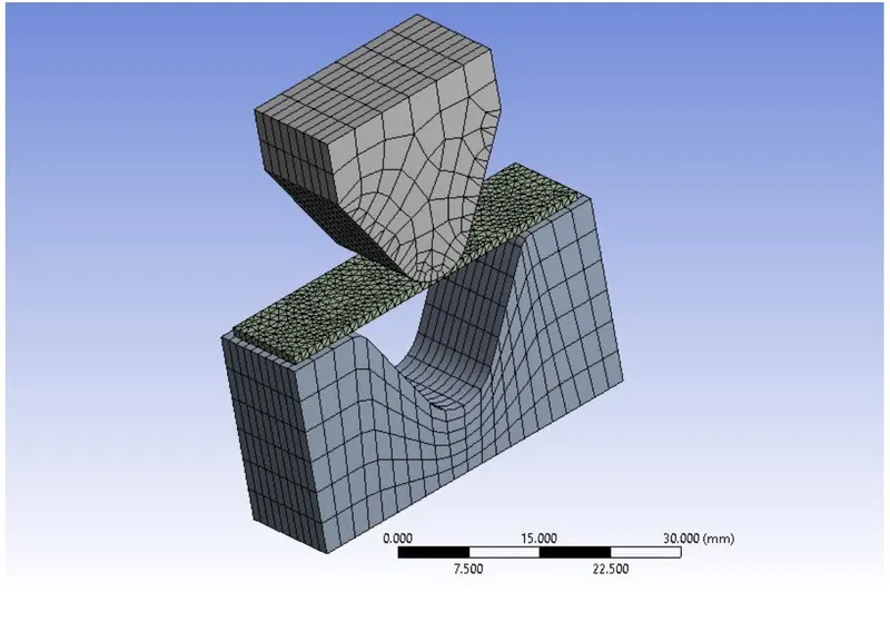
The meshed model image and mesh metric graph can be seen below :
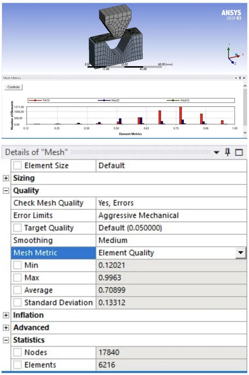
The mesh metric is utized to identify the elements according to their quality. The quality of the mesh is acceptable as most of the elements lie within a high-quality range of 0.8-1.0.
Contacts:
The assembly is modeled in such a way that there will be a frictional contact between the punch and the sheet metal and sheet metal and die.
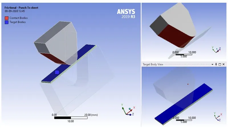
since all the parts are modeled as flexible bodies a certain set of rules was followed in defining the contact and target otherwise it may result in the interpenetrating of elements.
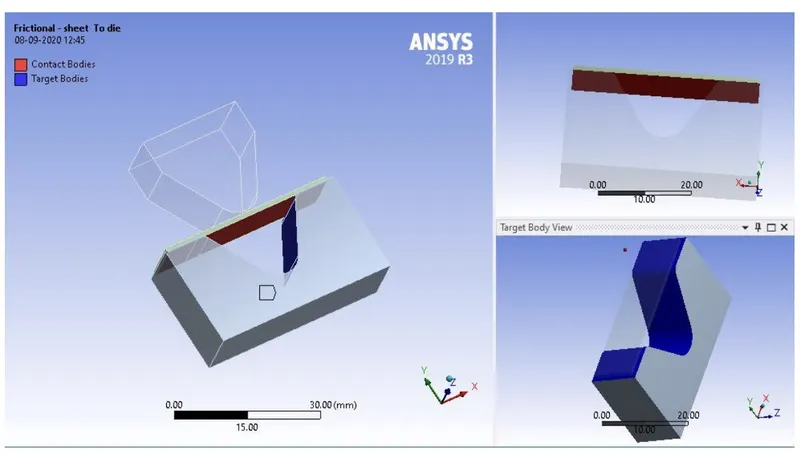
The flat surface was given as the target.
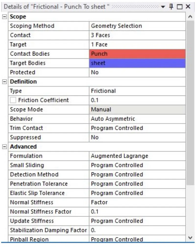
Considering the various advantages of Augmented Lagrange formulation such as better accuracy less computation time etc, it is chosen for this simulation stiffness factor of 0. was given which is generally recommended for bending applications.
Analysis settings:
The analysis was carried out in ten steps with the same settings
for each of the steps. The large deflection was enabled to
account for the large deformation in the analysis. The direct
type of solver is used. A structure could become unstable if the
lead reaches the buckling value or when the material becomes
unstable.
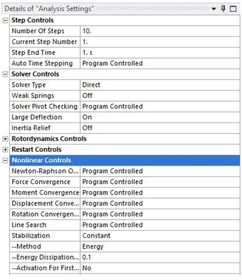
Hence this may cause a problem in convergence. o overcome this the nonlinear stabilization technique was followed. Since the stabilizing force is dependent on energy dissipation a constant value an energy dissipation, a constant value of energy dissipation was defined. A lower value of 0.1 was used to avoid the stiffer response of the system
Punch displacement:
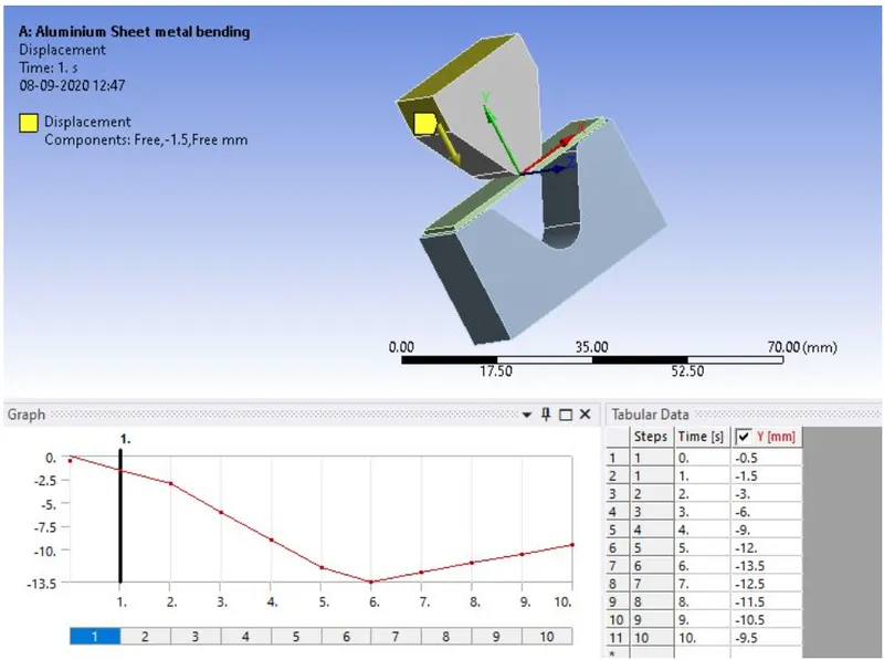
Punch was given with the displacement for each time step such that it advances till it strikes the sheet metal and returns after the bending has been performed.
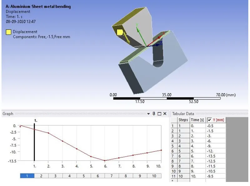
Sheet metal displacement :
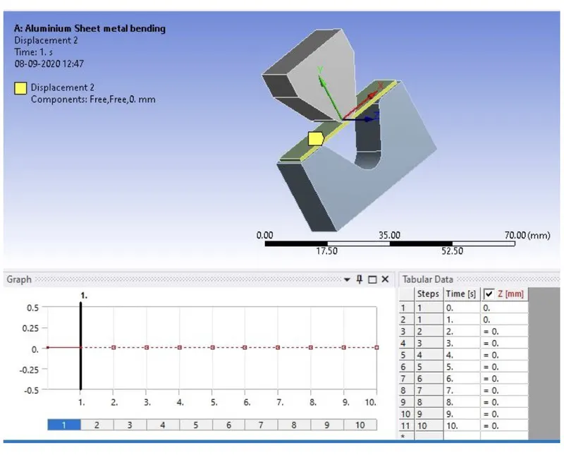
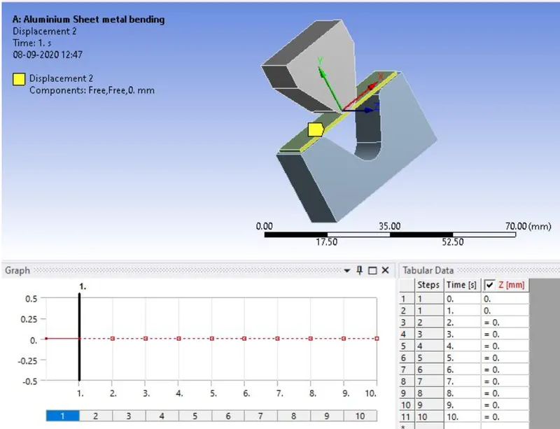
The sheetmetal was constrained in moving along the z-direction by fixing the values of the displacement as zero for all the time steps.
Die displacement :
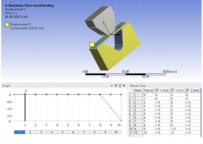
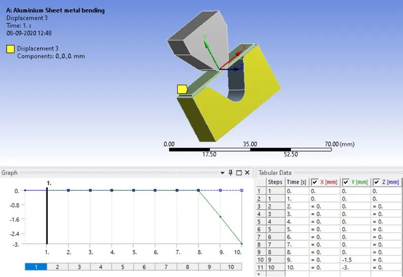
Die was made to be in contact with the sheet metal till the bending occurs and it displaces away from the sheet metal such that the sheet metal can be removed.
Result for case-1 :
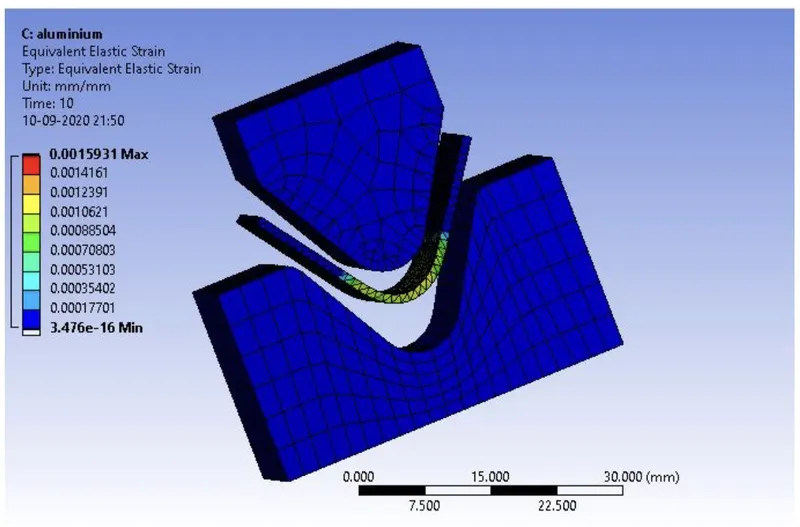
Equivalent elastic strain for Aluminium Alloy-1199
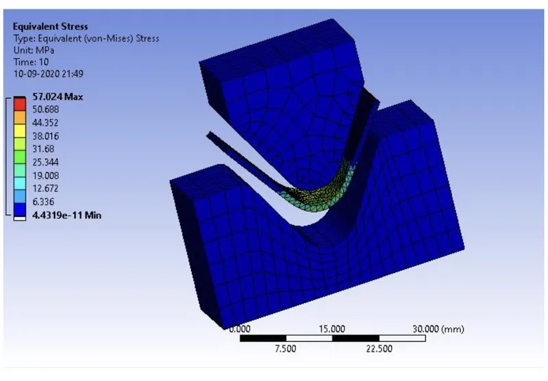
Equivalent stress for Aluuminium Alloy-1199
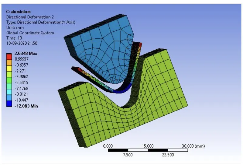
Total deformation in the Y direction for Aluuminium Alloy-1199
For copper Alloy NL :
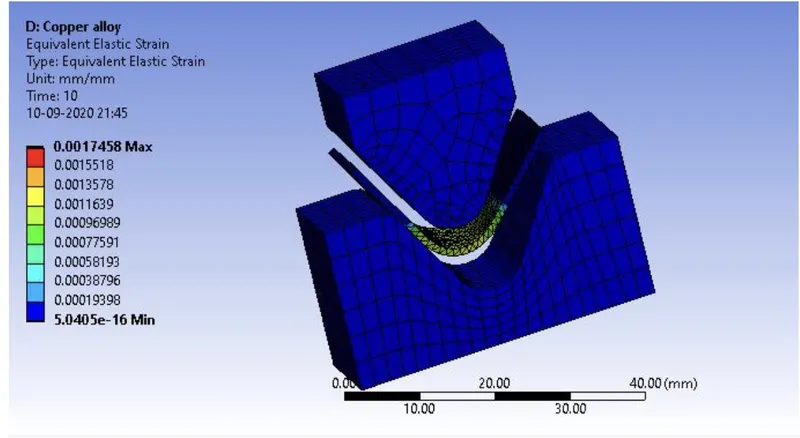
Equivalent elastic strain for Copper Alloy NL
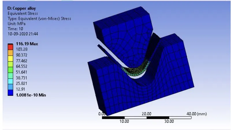
Equivalent stress for Copper Alloy NL
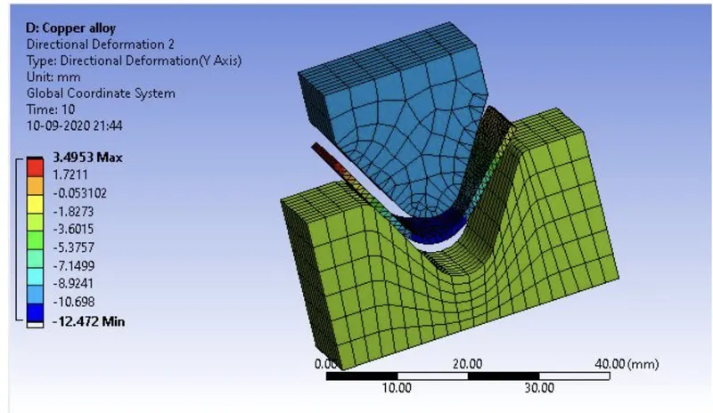
total deformation in the Y direction for Copper Alloy NL
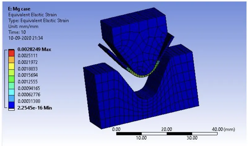
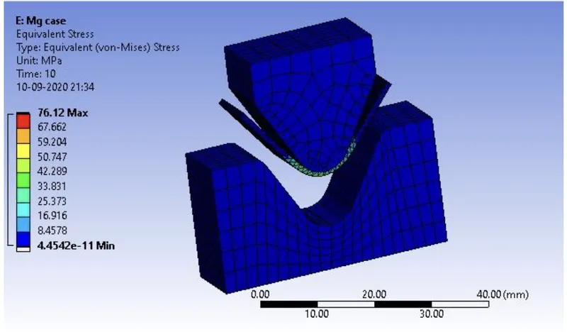
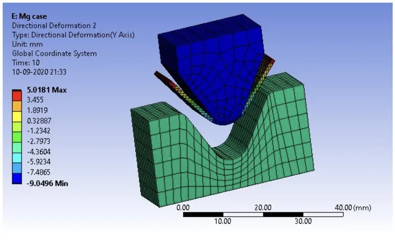
For Magnesium Alloy NL :
Equivalent elastic strain for Magnesium Alloy NL
Equivalent stress for Magnesium Alloy NL
total deformation in the Y direction for Magnesium Alloy NL
Result :
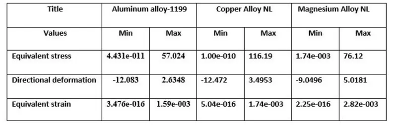
From the above table, we can see that equivalent stress is maximum in the Copper alloy and minimum in the Aluminium alloy
• As of stress in the sheet copper alloy has maximum stress in the sheet and Aluminium alloy has a minimum that can be seen in the animations.
• Directional deformation in the -axis is maximum in Magnesium alloy and minimum in Aluminum alloy.
• Lastly, the Equivalent strain is maximum in Magnesium
alloy and minimum in Aluminum alloy.
CASE-2
Case 2: With the material as Aluminium Alloy, change the friction coefficient to 0.19 and running the analysis as mentioned in Case 1. Compare the results with the in case 1.
Meshing:
The sheet metal and faces of punch and die which comes in contact with a sheet, the sheet has alone meshed with anelement size of Imm. other parts have meshed with an element size of 4mm.
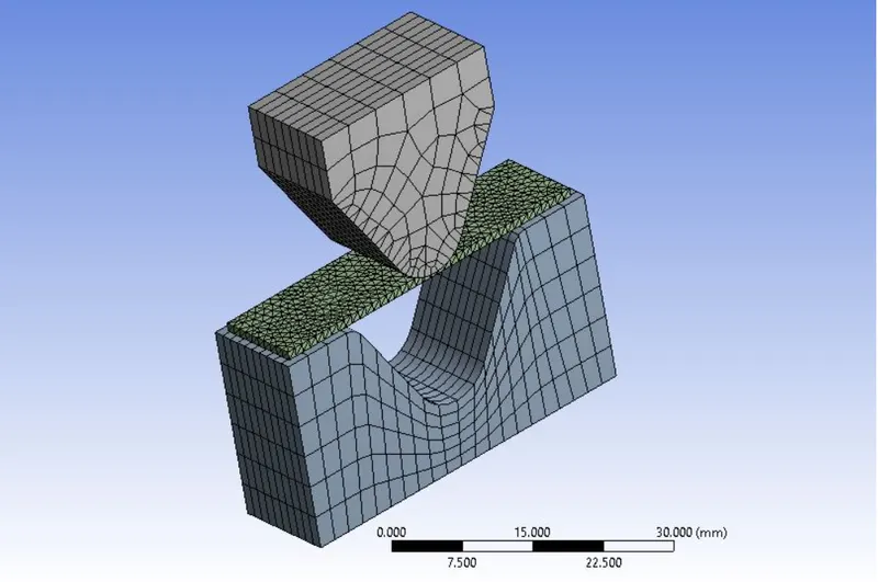
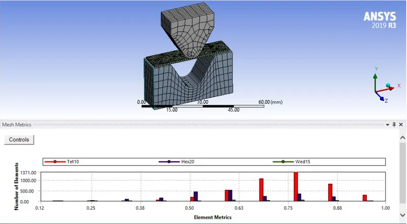
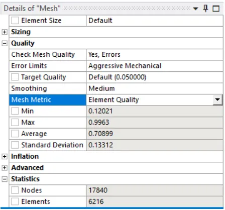
The mesh metric is utilized to identify the elements according to their quality. The quality of the mesh is acceptable as most of the elements lie within a high-quality range of 0.8-1.0.
Contacts:
The assembly is modeled in such a way that there will be a frictional contact between the punch and the sheet metal and sheet metal and die.
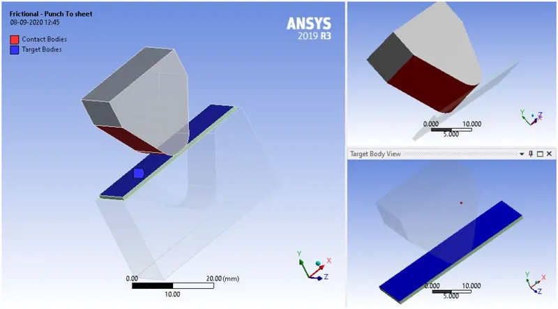
since all the parts are modeled as flexible bodies a certain set of rules was followed in defining the contact and target otherwise it may result in the interpenetrating of elements.
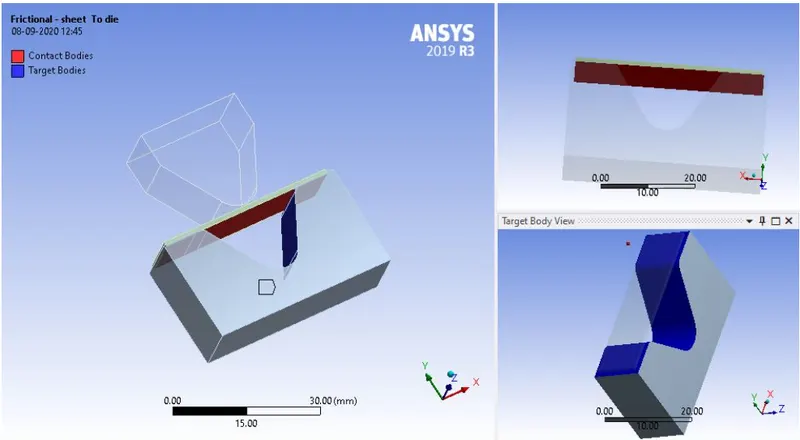
The flat surface was given as the target.
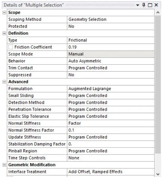
Considering the various advantages of Augmented Lagrange formulation such as better accuracy less computation time etc, it is chosen for this simulation stiffness factor of 0.19 was given which is generally recommended for bending applications.
Analysis settings:
The analysis was carried out in ten steps with the same settings for each of the steps. The large deflection was enabled to account for the large deformation in the analysis. The direct type of solver is used. A structure could become unstable if the lead reaches the buckling value or when the materidr becomes unstable.
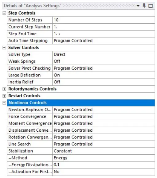
Hence this may cause a problem in convergence. o overcome this the nonlinear stabilization technique was followed. Since the stabilizing force is dependent on energy dissipation a constant value an energy dissipation, a constant value of energy dissipation was defined. A lower value of 0.1 was used to avoid the stiffer response of the system
Punch displacement:
Punch was given with the displacement for each time step such that it advances till it strikes the sheet metal and returns after the bending has been performed.
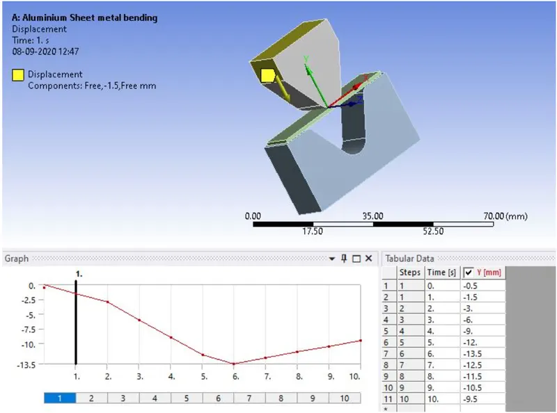
Sheet metal displacement :
The sheetmetal was constrained in moving along the z-direction by fixing the values of the displacement as zero for all the time steps.
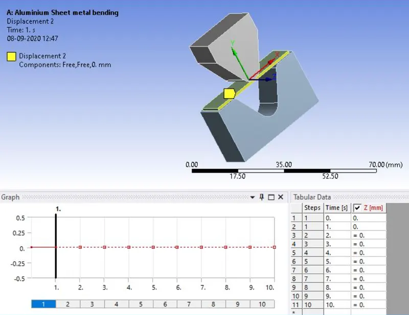
Die displacement :
Die was made to be in contact with the sheet metal till the bending occurs and it displaces away from the sheet metal such that the sheet metal can be removed.
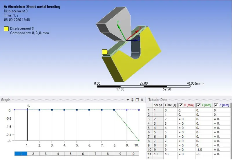
Result for case-2 :
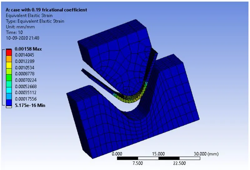
Equivalent elastic strain for Aluminium Alloy-1199 with a frictional coefficient of 0.19
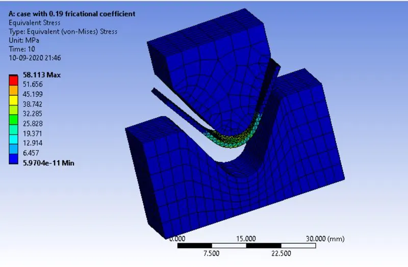
Equivalent stress for Aluuminium Alloy-1199 with a frictional coefficient of 0.19
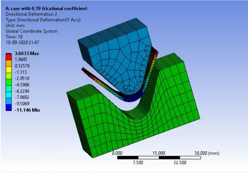
total deformation for Aluuminium Alloy-1199 with a frictional coefficient of 0.19
Result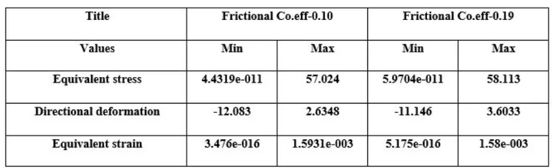
The frictional coefficient will have an impact on the punch force needed and therefore it is useful to keep it as low as possible. The contact tool is used to obtain the frictional stress between the contact regions.
As the frictional coefficient increases Equivalent stress and Directional deformation increase and Equivalent strain have been decreased as we can see it in the above table.
Case 3: Refine the mesh on the plate such that it doesn't cross the academic limit. With Aluminium alloy as material, run the analysis as in Case 1 and compare the results.
Meshing:
For case-3
The sheet metal and faces of punch and die which comes in contact with a sheet, the sheet has alone meshed with an element size of 0.7 mm. other parts have meshed with an element size of 4mm.
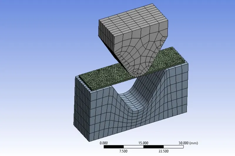
The meshed model image and mesh metric graph can be seen below :
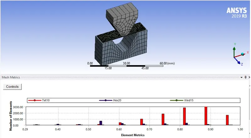
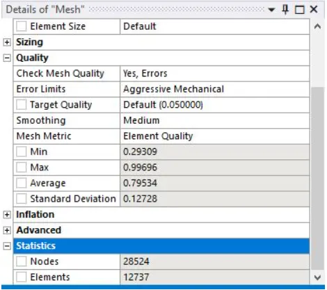
The mesh metric is utilized to identify the elements according to the quality. The quality of the mesh is acceptable as most of the elements lie within a high- quality range of 0.9-1.0
Contacts :
The assembly is modeled in such a way that there will be a frictional contact between the punch and the sheet metal and sheet metal and die.
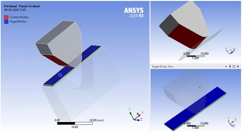
since all the parts are modeled as flexible bodies a certain set of rules was followed in defining the contact and target otherwise it may result in the interpenetrating of elements.
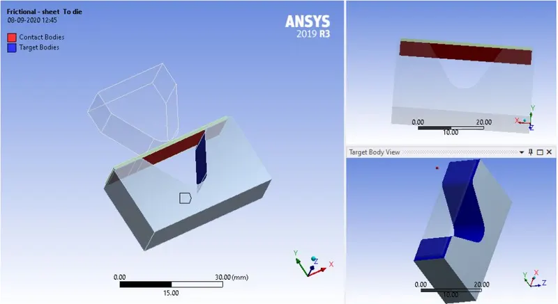
The flat surface was given as the target.
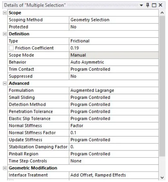
Considering the various advantages of Augmented Lagrange formulation such as better accuracy less computation time etc, it is chosen for this simulation stiffness factor of 0.19 was given which is generally recommended for bending applications.
Analysis settings:
The analysis was carried out in ten steps with the same settings for each of the steps. The large deflection was enabled to account for the large deformation in the analysis. The direct type of solver is used. A structure could become unstable if the lead reaches the buckling value or when the materidr becomes unstable.
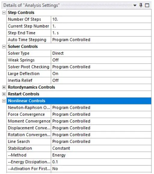
Hence this may cause a problem in convergence. o overcome this the nonlinear stabilization technique was followed. Since the stabilizing force is dependent on energy dissipation a constant value an energy dissipation, a constant value of energy dissipation was defined. A lower value of 0.1 was used to avoid the stiffer response of the system
Punch displacement:
Punch was given with the displacement for each time step such that it advances till it strikes the sheet metal and returns after the bending has been performed.
Sheet metal displacement :
The sheetmetal was constrained in moving along the z-direction by fixing the values of the displacement as zero for all the time steps.
Die displacement :
Die was made to be in contact with the sheet metal till the bending occurs and it displaces away from the sheet metal such that the sheet metal can be removed.
Result for case-3 :
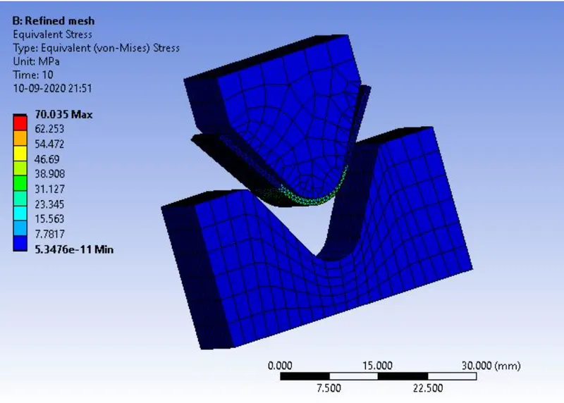
Equivalent stress for Aluuminium Alloy-1199
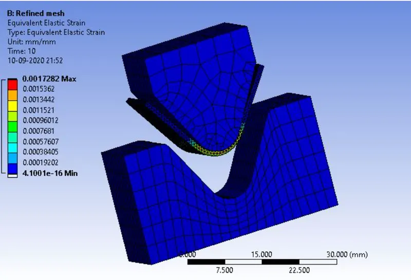
Equivalent elastic strain for Aluminium Alloy-1199
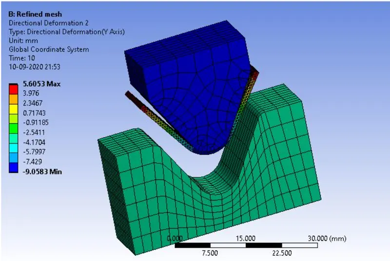
total deformation in the Y direction for Aluuminium Alloy-1199
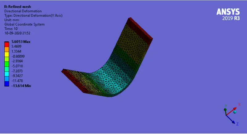
Animation for the total deformation on the sheet in the Y direction for Aluminium Alloy-1199
Results :-
As the mesh gets finer the results will become more accurate.From the above table, we can see that as the mesh gets finer the results get more accurate.
Conclusion :-
Performed a structural analysis on sheet metal with different material and frictional coefficient. A grid dependency test was also performed to optimize the element size for better accuracy.