Challenge

Week -2

  • AIM 1 :-

    To create a Simulink model of Doorbell using solenoid block with the following details:

In the above arrangement, when the switch is closed the electromagnet receives electrical power from the battery and pulls the metal arm to hit the bell producing sound.

Create a situation where the switch is closed for 2 seconds and then released. Observe the physical movement of the plunger.

Assume remaining parameters.

  • METHODOLOGY :-

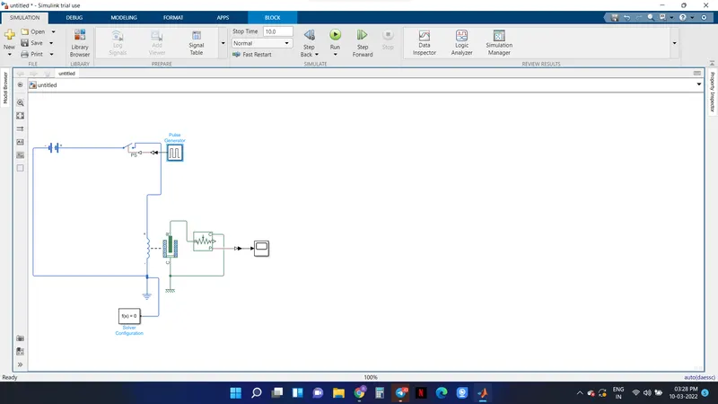
As shown in the figure; components used are a battery, a switch, a pulse generator, a solenoid, a ideal Translational Motion Sensor , a scope , a Solver Configuration, a Mechanical Translational Reference and a Electrical Translational Reference.

At very first there si a battery and after that there is a swith to operate the circuit then to generate pulse as output the switch is connected to a pulse generator but, as the circuit is in Simulink, a converter is to be used which is called as 'Simulink to PS convertor'. Then is a solenoid block as it is a elecrical so Electrical Translational Reference is used as every circuit needs to be grounded , after solenoid there is a ideal Translational Motion Sensor and to see the output a scope is added at the last but, as solenoid is in simscape , so as to convert it to simulik to attach a scope a converter called 'PS to Simulink' is used. The output is attached in result.

  • RESULTS :-

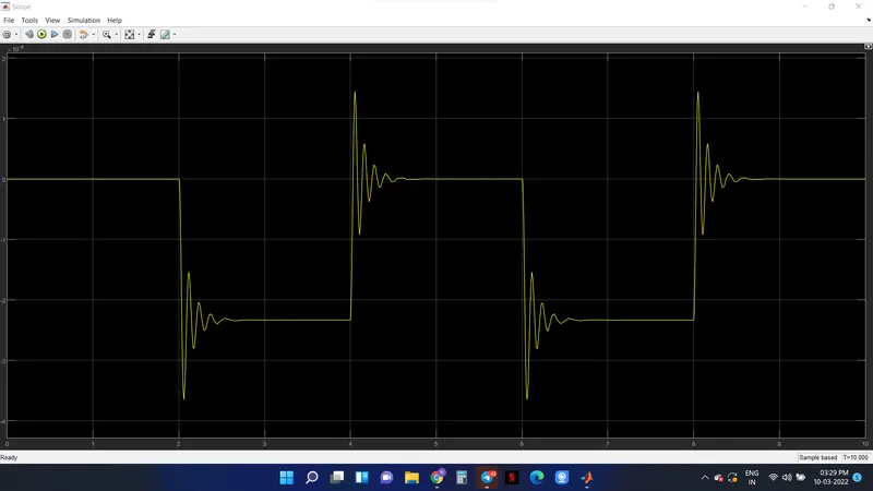
As a result we get a proper pulse showing ON and OFF complete cycle the configuration used is Amplitude is 1, Period is 4 pulse width is 50, Phase delay is 2 and simple time is 1. The output of scope is attached;

SNAPSHOT of Circuit :
SNAPSHOT of Scope :
  • AIM 2 :-

To use a thermistor to sense the temperature of a heater & turn on or turn off the fan as per the below conditions:

Temperature source: 20 °C from 0 to 10 seconds, 27 °C from 10 to 30 seconds, 23 °C from 30 to 50 seconds

Fan conditions: ON if the temperature above 25 °C, OFF otherwise.

  • METHODOLOGY :-

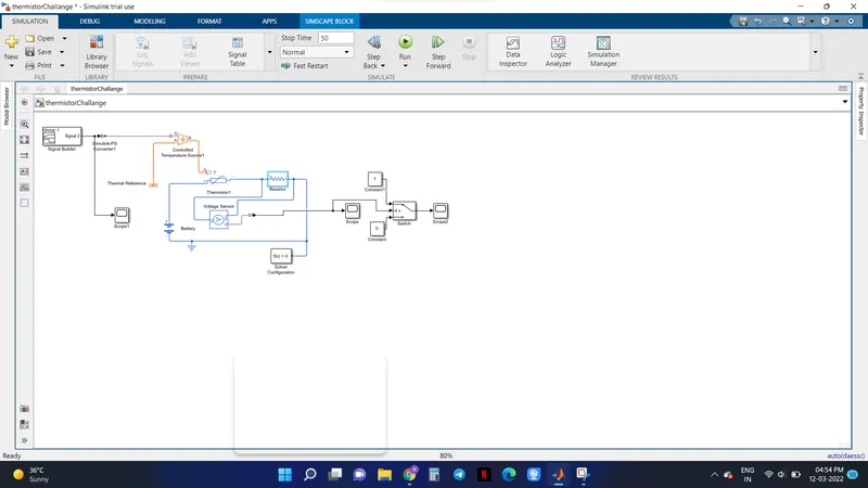
In the above circuit, an NTC thermistor from the following library of Simulink has been used: Simscape / Foundation Library / Electrical /Electrical Elements.

This thermistor has two electrical ports which are + and - terminals which will be connected to a de voltage source from Simscape/Electrical / Sources. Along with two terminals, we had a thermal port H which provides the resistance temperature. This port A has been connected to a controlled temperature source block which will provide the required temperature according to the signal provided to its A port which is the source inlet and source outlet port B is connected to the A port of the thermistor. NTC thermistor resistance is calculated using the below formula
Ro = Ro(1 + a(T - To))
Where RO is the nominal resistance at the reference temperature TO a is the temperature coefficient.
The thermal behavior of the block will be represented by
Q = Kdtc dT/dt -i^2R
Where Q is the net heat flow into port H/A
Kd is the Dissipation factor parameter value,
tc is the Thermal time constant parameter value,
dT/dt is the rate of change of the temperature.
i is the current through the resistor.
A ramp signal which gives a linear increase output is connected to a Simulink - PS converter which converts the Simulink signal to a physical signal and then connected to the physical input S port of the controlled temperature source block.
A voltage sensor from Simscape / Electrical / Sensors connected parallel to the thermistor which means + of voltage sensor to + of the thermistor and - of voltage sensor to - of the thermistor to get the voltage across thermistor. A current sensor from Simscape / Electrical /Sensors connected series to the thermistor which means - of the thermistor to + of current sensor and - of current sensor to - of the dc voltage sensor. An electrical reference from Simscape / Foundation Library / Electrical / Electrical Elements and solver configuration block from Simscape / Utilities has been connected in order to provide the required solver configuration parameters to the model to solve by the Simulink solver.
Obtained Simulink outputs of voltage and current by connecting PS-Simulink converter to the respective sensors and connected to a divide block in order to get the resistance value.
R=V/I
Where,
R = resistance of the thermistor
V = voltage across thermistor
I= current passing through the thermistor
  • RESULTS :-

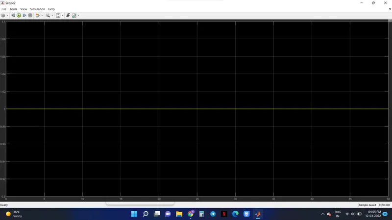
As a result we get 1 in scope 2 which indicates as circuit is ON.

Snapshot of circuit :
Snapshot of Scope :

SCOPE 1 :
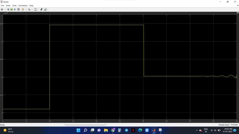
SCOPE 2 :
Your portfolio, next

Ship work like this
in your own course.

Talk to a career counsellor

Free 20-minute call. We'll map the right course to where you want to work.

By submitting you agree to our Terms and Privacy Policy.

Talk to a career counsellor

Free 20-minute call. We'll map the right course to where you want to work.

By submitting you agree to our Terms and Privacy Policy.