Week 3 - Pitot tube
1. A pitot static tube geometry is attached below.
a.You are required to do a literature review of pitot-static tube. Also establish a relationship between Total (stagnation) pressure and static pressure
b.You are required to create surfaces and fill it separately for Total pressure port and static pressure port as shown below.
2. For the values of velocity given below calculate the total and static pressures and find the error in percentage for velocity.
|
Velocity(m/s) |
Gauge Pressure (Pa) |
|
240 |
-2817 |
|
100 |
33287 |
|
62 |
65780 |
Solution:
Theory:
A Pitot-static tube is widely used for measuring unknown speeds in air flow, for example, it is used to measure airplane airspeed. By Bernoulli's principle, airspeed is directly related to variations in pressure. Therefore, the Pitot-static tube senses the stagnation pressure and static pressure. It is connected to a manometer or pressure transducer to obtain pressure readings, which allows airspeed prediction.
There are 3 types of Pitot tube.

Simple Pitot tube - Total pressure is measured.
Static tube - Static pressure is measured.
Pitot-static tube - Total & Static pressure
Bernoulli's principle states that an increase in the speed of a fluid occurs simultaneously with a decrease in pressure and vice versa. Specifically, if the speed of a fluid decreases to zero, then the pressure of the fluid will increase to its maximum. This is known as the stagnation pressure or total pressure. One special form of Bernoulli's equation is as follows:
Stagnation pressure = static pressure + dynamic pressure

where the stagnation pressure, Po, is the pressure if the flow speed is reduced to zero isentropically, the static pressure, Ps, is the pressure the surrounding fluid is exerting on a given point, and the dynamic pressure, Pd, also called ram pressure, is directly related to the fluid density, ρ, and flow speed, V, for a given point. This equation only applies to incompressible flow, such as liquid flow and low-speed air flow (generally less than 100 m/s).
From the above equation, we can express flow speed, V, in terms of pressure differential and fluid density as:
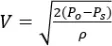
In the 18th century, French engineer Henri Pitot invented the Pitot tube [1], and in the mid-19th century, French scientist Henry Darcy modified it to its modern form [2]. In the early 20th century, German aerodynamicist Ludwig Prandtl combined the static pressure measurement and Pitot tube into the Pitot-static tube, which is widely used today.
A schematic of a Pitot-static tube is shown in Figure 1. There are 2 openings in the tubes: one opening faces the flow directly to sense the stagnation pressure, and the other opening is perpendicular to the flow to measure the static pressure.
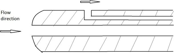
Figure 1. Schematic of a Pitot-static tube.
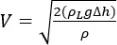
The pressure differential is required to determine the flow speed, which is typically measured by pressure transducers. In this experiment, a liquid column manometer is used to provide a good visual to measure the change in pressure. The pressure differential is determined as follows:

where Δh is the height difference of the manometer, ρL is the density of the liquid in the manometer, and g is the acceleration due to gravity. Combining equations 2 and 3, the flow speed is predicted by:
Procedure:
- 1. Geometry preparation
The geometry is imported in fluent.
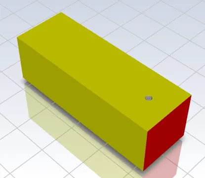
- 2. Meshing
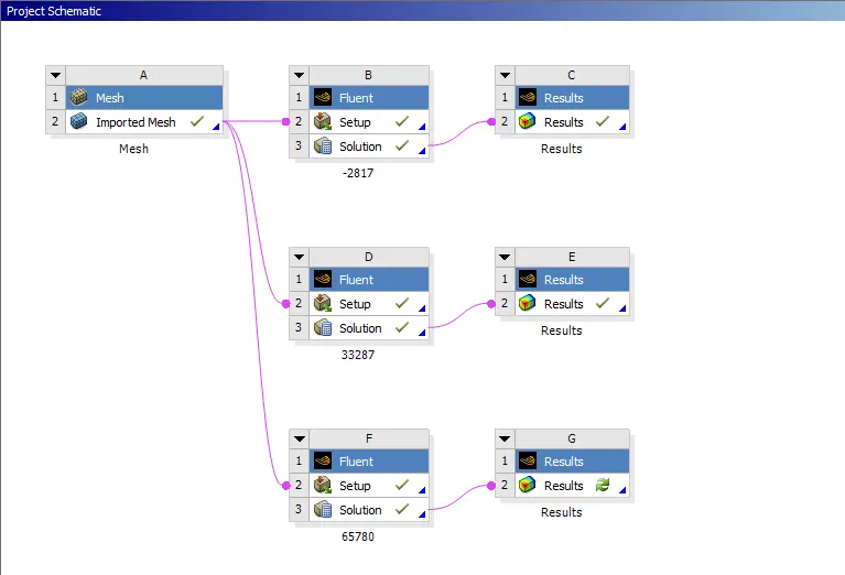
The mesh file given is imported into the Mesh tab and Fluent is linked to the geometry. for the post process, A result module is add. See schematic representation of the entire project below.
- 3. Setup using Ansys Fluent
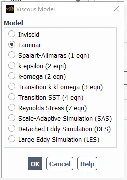
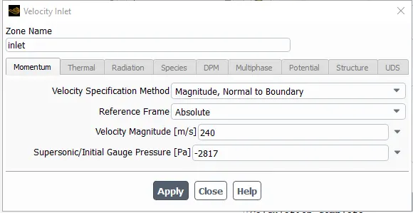
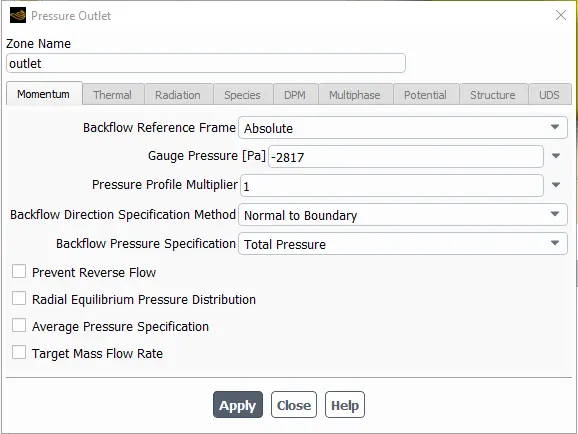
Similar inputs are performed for the other two points.
- 4. Results & Pots
For 240 m/s Velocity & -2817 Pa pressure at the inlet
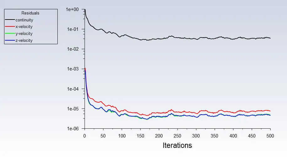
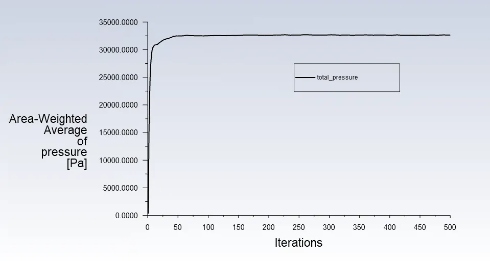
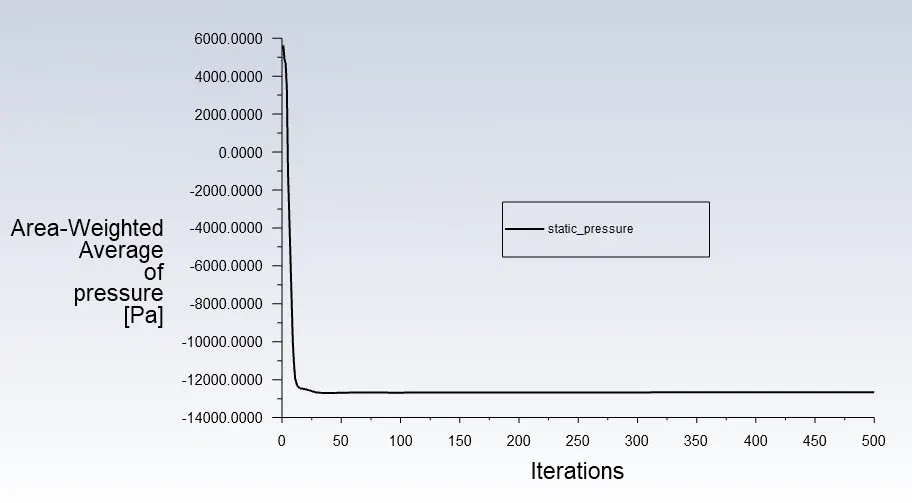
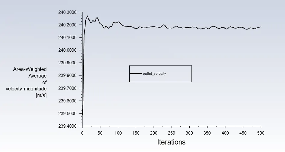
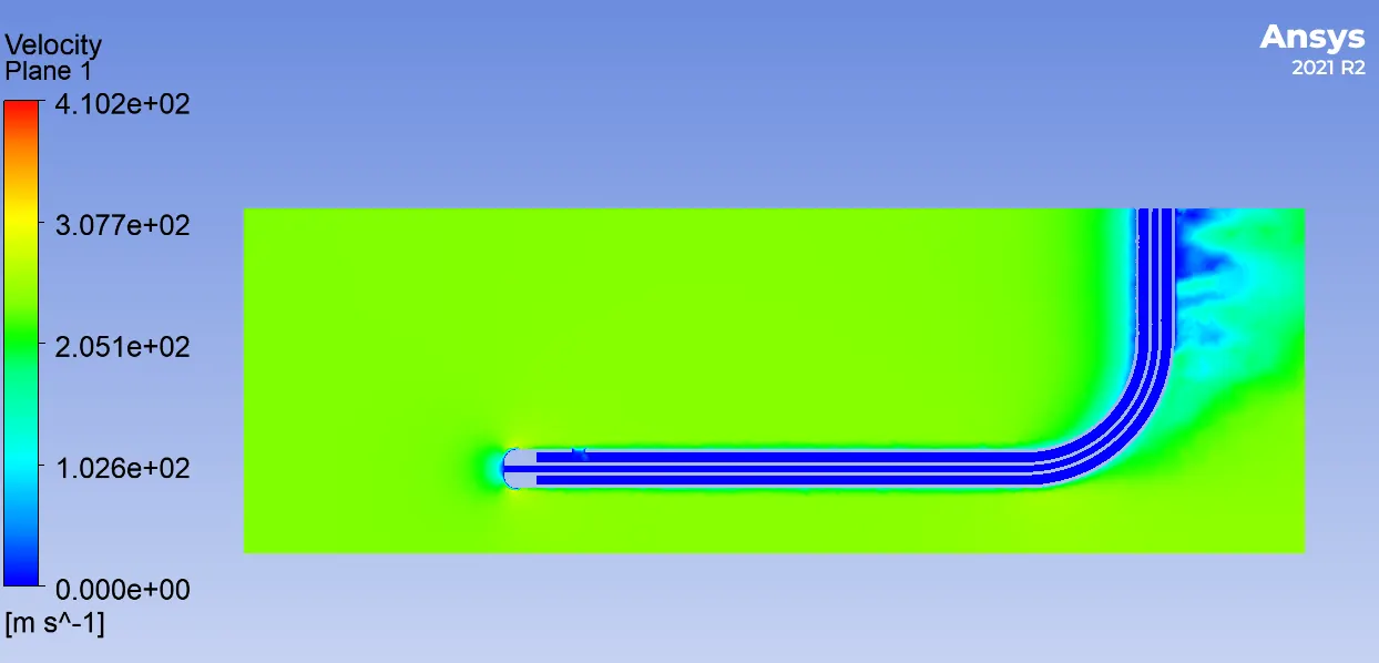
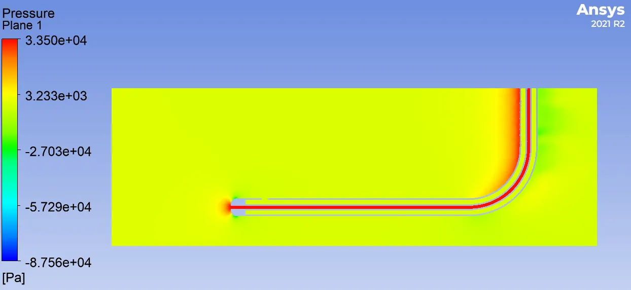
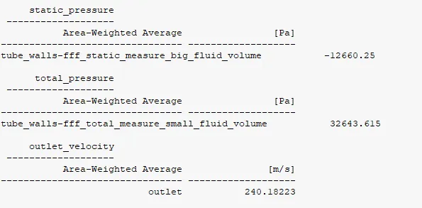
For 100 m/s Velocity & 33287 Pa pressure at the inlet
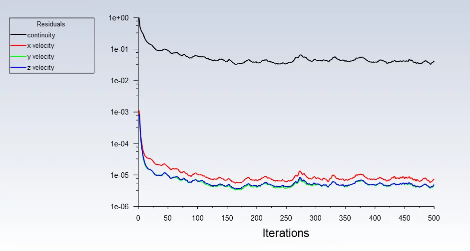
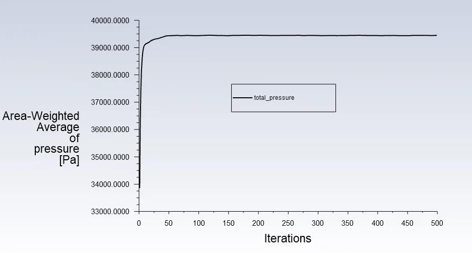
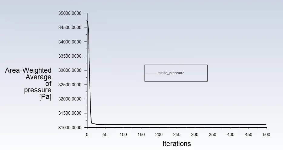
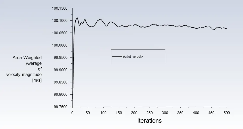
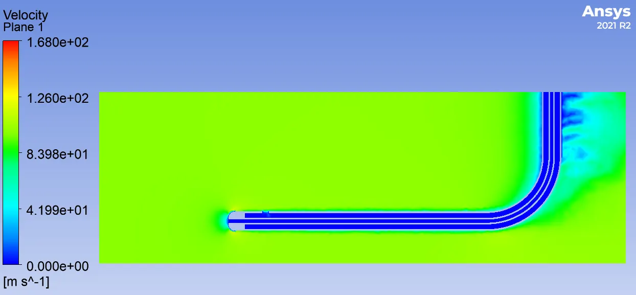
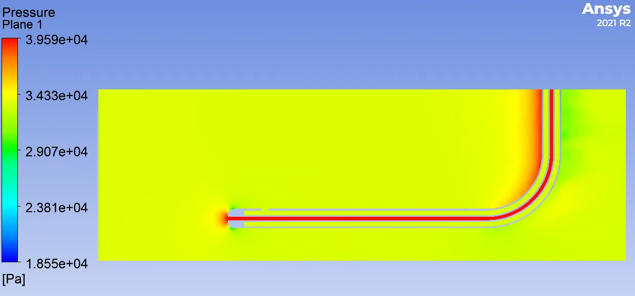
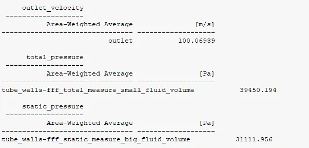
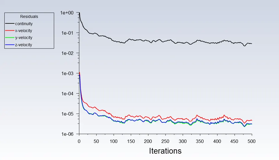
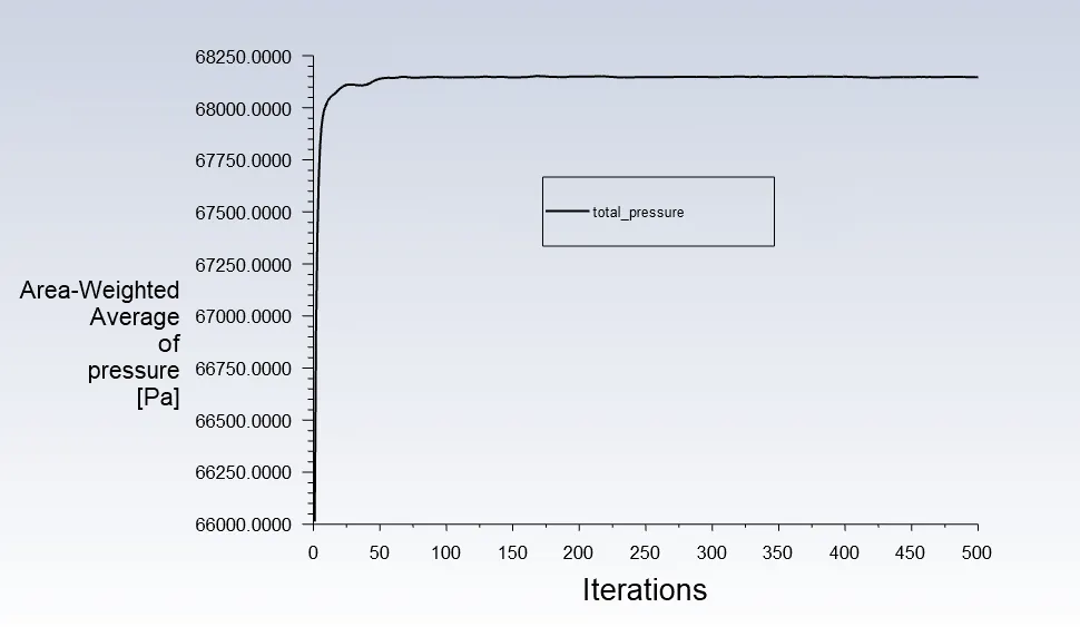
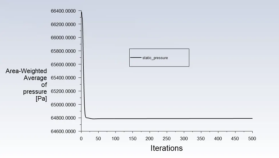
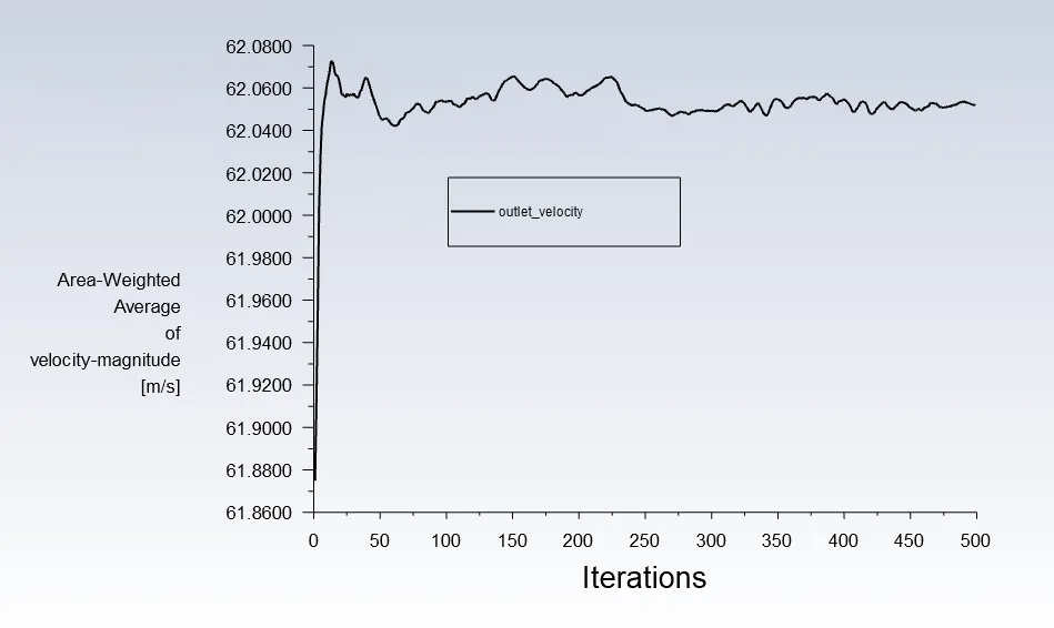
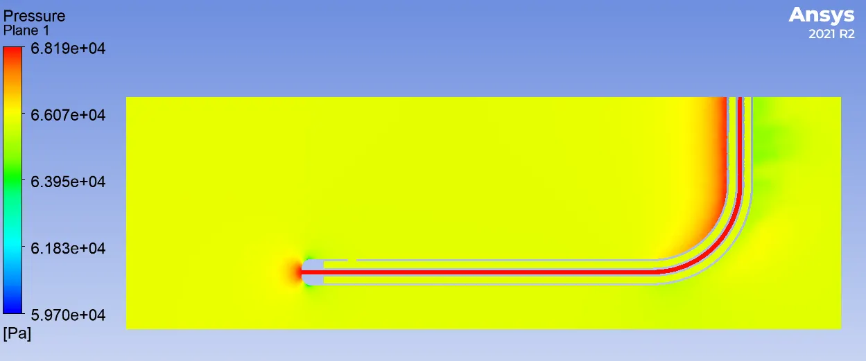
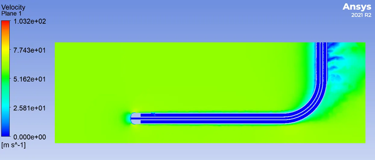
For 62 m/s Velocity & 65780 Pa pressure at the inlet
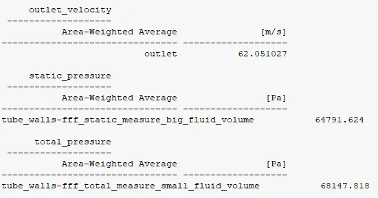
Conclusion:
- For all the points of measurement, velocity Error is less than 5%.
- The pitot tube is explained with the relationship between Total (stagnation) pressure and static pressure
- The pitot tube simulation is carried out with different velocities to predict the static and total pressure at the outlet.
- The variation of error is marginal and lies within the acceptable region.
