Week 3 - Pitot tube
Aim: To perform simulation on the pitot tube using Ansys
- To do a literature review of the pitot-static tubes. Also, establish a relationship between Total (stagnation) pressure and static pressure
- To calculate the total and static pressures and find the error in percentage for velocity.
Introduction:
pitot tubes are used for fluid flow measurement to find the velocity of the boat in water, the velocity of aircraft, and the velocity of gases in industries. Pitot tubes actually measure the pressure that is used in calculating the velocity of the fluid or body. Pitot tubes will not calculate the velocity directly. There are commonly three types of pitot tubes.
- Simple pitot tube: Measures the total pressure of the incoming fluid
- Static tube: Measures the static pressure of the incoming fluid
- Pitot static tube:
- Measures the total pressure and the static pressure. It will be used in low-speed aircraft's Measurement will be accurate in the low Mach conditions.
- The construction of the pitot-static tube is different from the other two tubes. It is the combination of the Features of the other two tubes.
- It has an opening at the center that runs through the tube. This opening is used to measure the total pressure of the incoming fluid.
- It also has two openings on the sides and runs through the tube without any contact with the other opening. This is used to measure the static pressure of the incoming air.
The relation between the Static pressure Total pressure and the velocity of the fluid is as follows
`V = sqrt(2((P_(Total)-P_(Static))/rho)`
V = velocity of the body
`rho` - density of the fluid
`P_(Total)` - Total pressure of the Fluid
`P_(Static)` - Static pressure of the Fluid
Advantages:
- Very Small and do not contain any moving parts.
- Installation and device costs are less.
- It doesn't Create considerable pressure loss.
- Easy to incorporate into the system.
- There is no need for the additional static pressure measuring device which reduces error.
Disadvantages:
- Foreign material in a fluid can easily clog the pitot tube and disrupt normal reading as a result.
- Less accurate.
- Can only function properly in a preferred Mach range.
Need for the pitot-static tube:
Airplanes rely on several different systems to determine their position, speed, altitude, and orientation. These systems can be extremely complex, like GPS, or quite simple, like a Pitot tube. Once the airplane is in the air, it can't rely on the engine’s rotation, or on the rotation of its wheels to estimate its speed. So to measure the speed of the plane in mid-air, pressure measurements and temperature measurements are needed. The total and static pressures are known from the pitot-static and the temperature to obtain the density of the incoming air, the true speed of the aircraft can be determined. The velocity can be calculated using the Relation between pressures and velocity if the flight is at a low subsonic speed but For higher speeds, the calculation is more involved and must take into account compressibility effects.
Procedure:
- Import the mesh model in the fluent setup
- Setting up boundary conditions, input the inlet velocity and pressure in the inlet boundary and feed the same pressure for the outlet as the pressure drop due to the pitot tube is very minute.
- In Viscous model is selected as laminar.
- A central plane XY is created for the pitot tube, the required contours are projected onto it.
- define the required reports for static pressure and total pressure in the static tube and total pressure tube respectively. the required contours are also defined.
- The velocity is calculated using the relation between the static, Total pressure, and velocity.
- Calculate the error % between the analytical and the actual velocity.
Plots for velocity (240 m/s)Gauge Pressure (2817 pa):
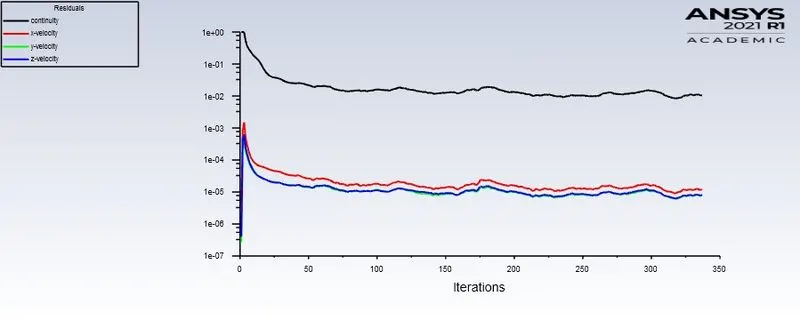
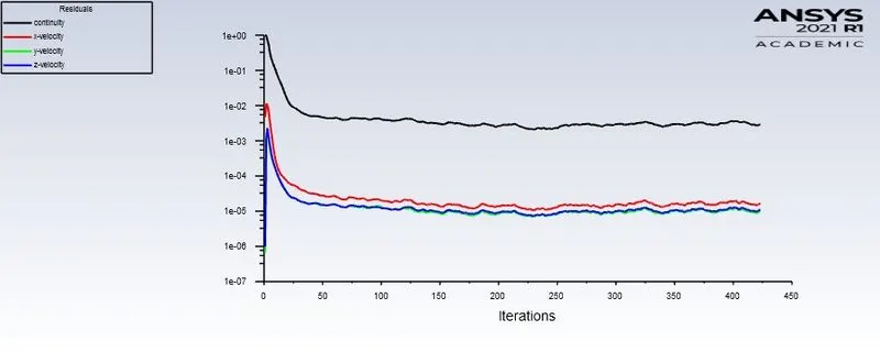
Residuals:
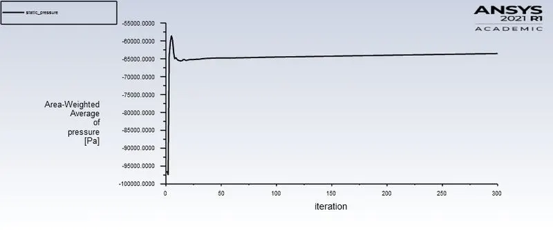
Static Pressure:
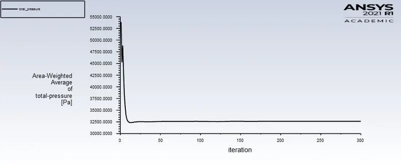
Total Pressure:
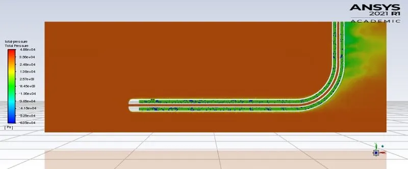
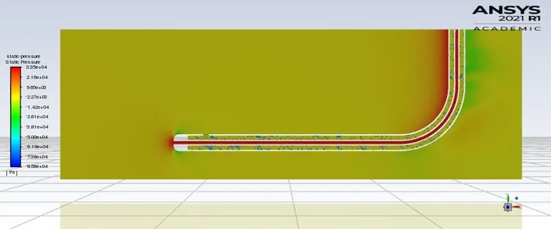
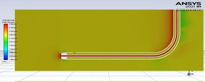
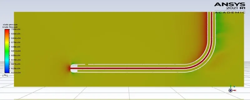
The pressure in the central tube is total pressure and pressure in the other tubes is the static pressure
Velocity Contour:
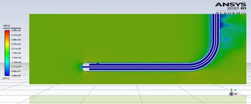
The velocity of the fluid in the pitot tube is zero as shown in the above contour and the pressure increases.
Static and Total Pressure displayed on the console

Analytical velocity calculation from the formula `V = sqrt(2((P_(Total)-P_(Static))/rho)`
`V = sqrt(2((64180.99-32606.172)/1.125)`
V = 236.92
The % error for the actual velocity and analytical velocity is 1.28. The error is less than 5%
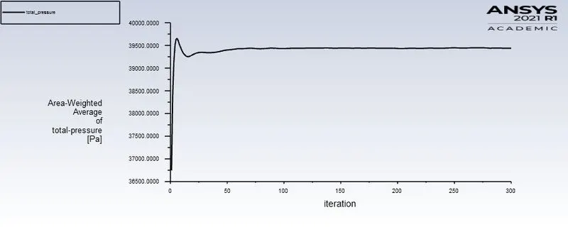
Plots for velocity (100 m/s)Gauge Pressure (33287 pa):
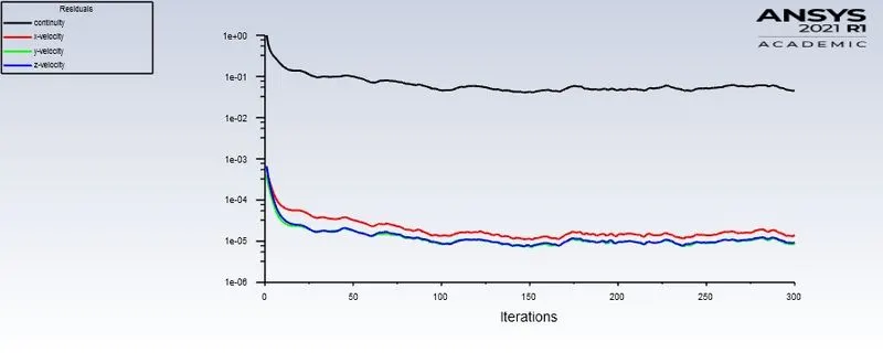
Static Pressure:
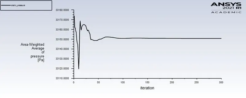
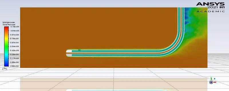
Total Pressure:
Static and Total Pressure displayed on the console

Calculating the velocity using the formula as shown for the above velocity we get
The percentage error for the actual and the analytical velocity is around 5%
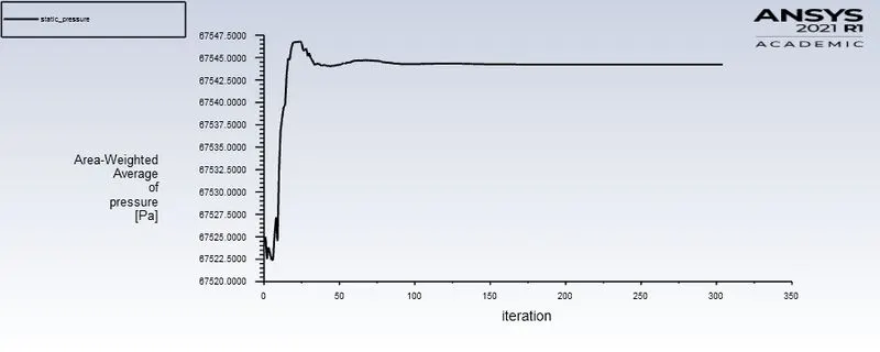
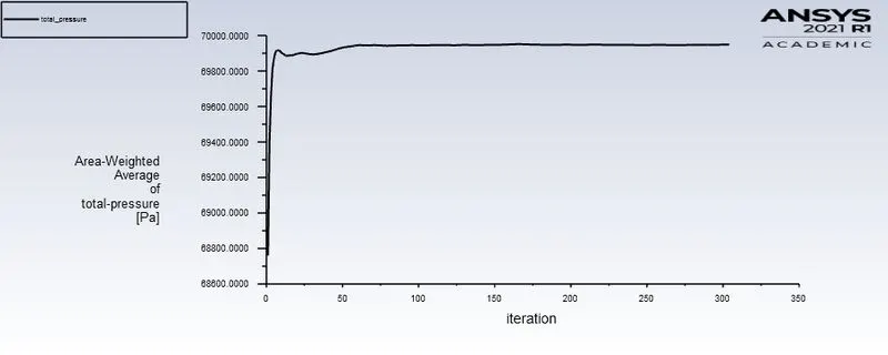
Plots for velocity (62 m/s)Gauge Pressure (62 pa):
Static Pressure:
Total Pressure:
Static and Total Pressure displayed on the console

The percentage error for the actual and the analytical velocity is around 5%
Conclusion:
The comparison of the actual and analytical results of velocity is performed by calculating the error and the error is around 5% which is acceptable for this kind of simulation.