Week 3-Meshing of Hood Challenge
Week 3-Meshing of Hood Challenge
QUALITY CRITERIA: Follow the below-mentioned quality criteria, mesh the component given below and assign thickness:
Target Element Length = 5 Units
|
S.N |
Quality Criteria |
Value |
|
1 |
Aspect Ratio |
5 |
|
2 |
Skewness |
45 |
|
3 |
Warping |
15 |
|
4 |
Taper |
0.5 |
|
5 |
Min. Length |
2 Units |
|
6 |
Max. Length |
8 Units |
|
7 |
Min angle Quad |
45 |
|
8 |
Max angle Quad |
135 |
|
9 |
Min angle Tria |
20 |
|
10 |
Max angle Tria |
120 |
|
10 |
Tria % |
10 |
AIM: The primary objective of this task is to proficiently employ the HyperMesh pre-processing tool for technical procedures, such as refining the geometry, extracting the mid-surface, and generating the mesh, on the given automobile hood component. Following this, the quality of the mesh produced will be evaluated according to the defined quality standards.
OBJECTIVE: The primary objective of this task is to effectively utilize the HyperMesh pre-processing tool to enhance the finite element analysis capability through geometry refinement, mid-surface extraction, and mesh generation on the provided automobile hood component. The quality of the resulting mesh will be evaluated based on established quality criteria to ensure optimal simulation accuracy and performance.
PROCEDURE: The process can be divided into the following phases:
Phase 1: Importing, Setup and Mid-surface generation.
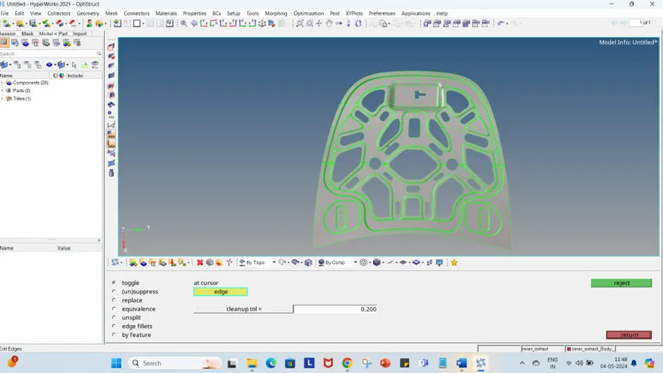
FIGURE – 1 IMPORTED MODEL
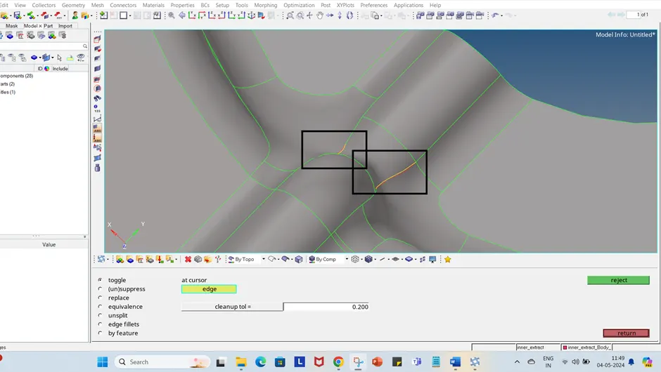
FIGURE – 2 CLEARING GEOMETRIC ERRORS
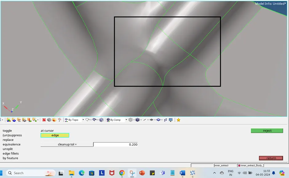
FIGURE – 3 GEOMETRIC ERRORS CLEARED
Once all geometric errors have been rectified, we can proceed with mid-surface generation to further refine the model for finite element analysis.
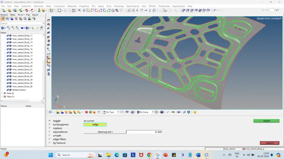
FIGURE – 4 MIDSURFACE GENERATED.
Given that the model is symmetric, the other half of the hood can be deleted, allowing mesh generation to be carried out on the first half only.
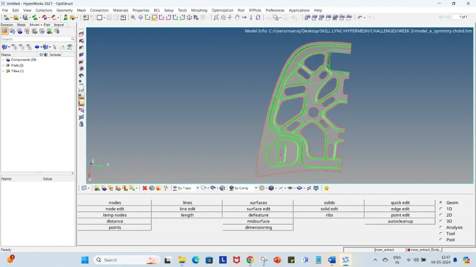
FIGURE – 5 SYMMETRY CUT PERFORMED.
Phase 2: Meshing the model.
The mesh will be generated on the entire model using the 2d auto mesh tool.
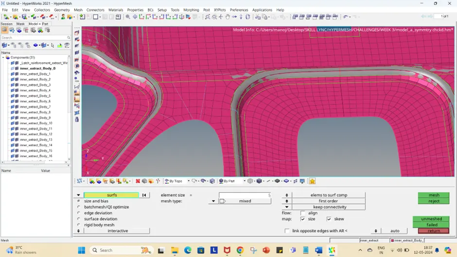
FIGURE – 6 Meshing the model.
The mesh parameters need to be defined before proceeding with the mesh. In this case the target element length is 5, in the Mesh quality tab enter the given quality criteria, min element length, max element length.
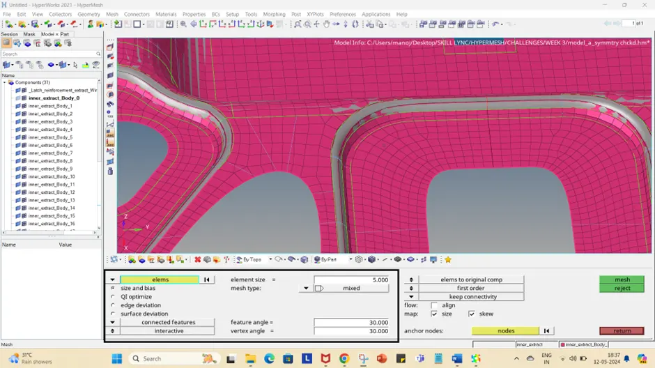
FIGURE – 7 Rebuilding the mesh using the Elements option.
The elements can be cleaned using the cleanup tools in the 2d elements panel.
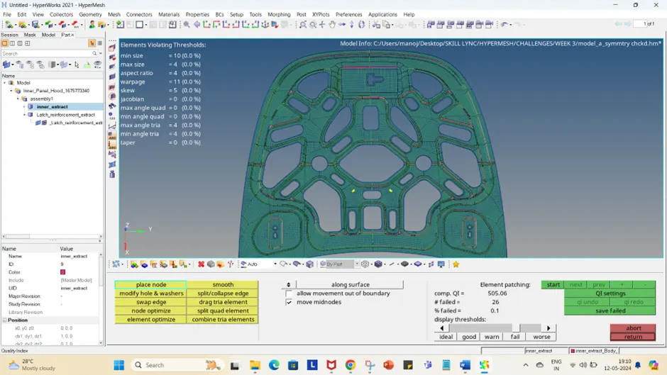
FIGURE – 8 Quality Index panel Clean up tool.
Once the mesh is generated the other half of the symmetric surface can be regenerated,
Reflect >> duplicate surface >> select y axis as reference plane >> reflect the surface

FIGURE – 9 Reflecting the other half.
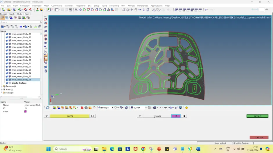
FIGURE – 10 Reflecting the other half.
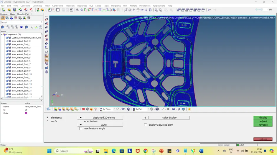
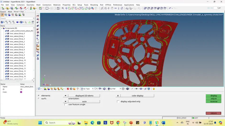
Figure 11 & 12 Normal check performed on the model
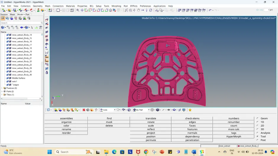
Figure 13 Fully meshed model.
When starting with any model, the initial step involves cleaning up the geometry, specifically by removing or adjusting unnecessary edges or lines. This is crucial for efficient meshing. It is essential to maintain only the critical lines and edges, facilitating the creation of a structured and straightforward mesh.
In cases where two fillets are separated by a minor gap, one edge can be toggled to simplify the meshing area. This adjustment helps prevent the creation of elements that are too small or too large. An important aspect of meshing is ensuring consistent mesh flow, which should align with the underlying geometry.
To enhance the quality of the analysis, minimizing triangular (tria) elements is advisable, as excessive tria elements can disrupt the mesh flow. Rotational quadrilateral (quad) elements should also be avoided as they can lead to misorientation during the analysis process and potentially yield inaccurate results.
While tria elements are sometimes unavoidable, particularly at curved or rounded sections of the model, careful attention must be paid to how these elements are integrated. Splitting the surface differently at these sections can help manage the element quality better.
In instances of poor-quality elements, it is possible to isolate and specifically work on these to make necessary corrections. Maintaining the continuity of mesh flow around tria elements is crucial.
By strategically arranging tria and quad elements and employing effective remeshing techniques, a high-quality mesh that supports accurate analysis outcomes can be achieved.
The model can also be found here : https://drive.google.com/drive/folders/1i5FmWl4L53Azs7LQFF2OFTQR_JXiJ8Fs?usp=sharing
due to file size restriction i have uploaded the hm model in the drive please use the above link.