Week 3-Meshing of Hood Challenge
Week 3-Meshing of Hood Challenge
Aim: meshing of car hood components using given quality criteria
Given quality criteria
| S.N | Quality Criteria | Value |
| 1 | Aspect Ratio | 5 |
| 2 | Skewness | 45 |
| 3 | Warping | 15 |
| 4 | Taper | 0.5 |
| 5 | Min. Length | 2 Units |
| 6 | Max. Length | 8 Units |
| 7 | Min angle Quad | 45 |
| 8 | Max angle Quad | 135 |
| 9 | Min angle Tria | 20 |
| 10 | Max angle Tria | 120 |
| 10 | Tria % | 10 |
Given model
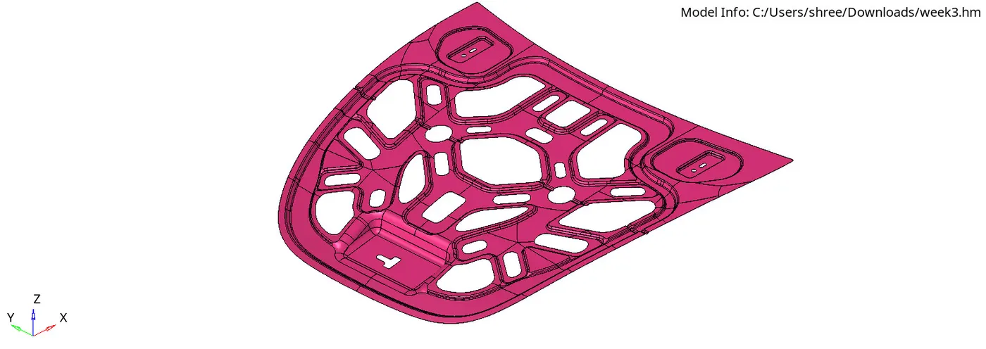
Note:
First, we need to learn about car body parts to understand the given component.
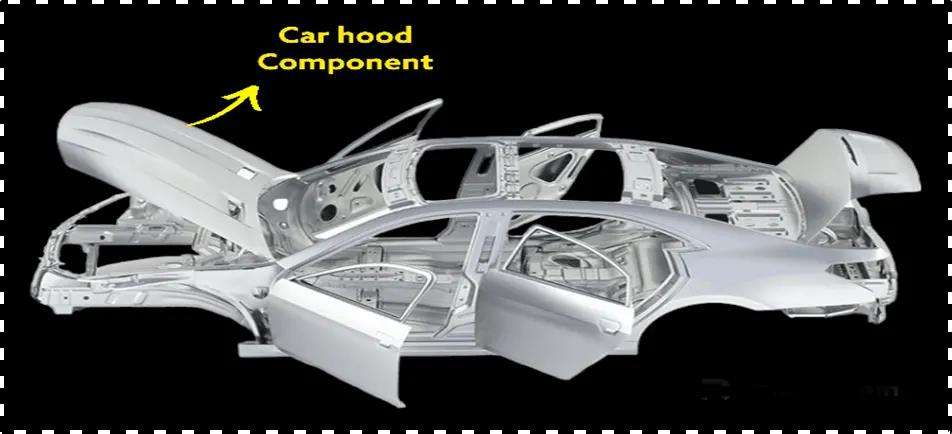
- The car hood is also called a bonnet.
- It protects the engine from dirt, debris, and weather.
- It also provides access to the engine for maintenance and repairs.
The following procedure for solving a hood component challenge using quality criteria.
procedure for a given component
1. Delete Solids:
● Access the "Solids" tab in the software interface.
● Select the solid components that need to be removed from the model.
● Use the delete key or right-click option to eliminate the selected solids.
● Confirm the deletion to ensure the removal of unwanted components from the model.
● Go to the "Solids" tab > Select solids > Delete.
2. Check for Free Edges or Deleted Surfaces:
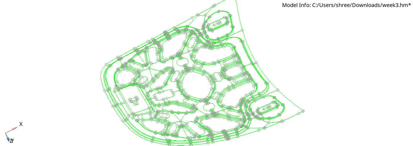
- Use wireframe geometry to easily identify the free edges
● Navigate to the "Geometry" tab within the software.
● Utilize the "Check" tool to scan for any free edges or deleted surfaces in the model.
● Review the generated report to identify and address any issues related to free edges or deleted surfaces.
3. Extract Mid Surface:
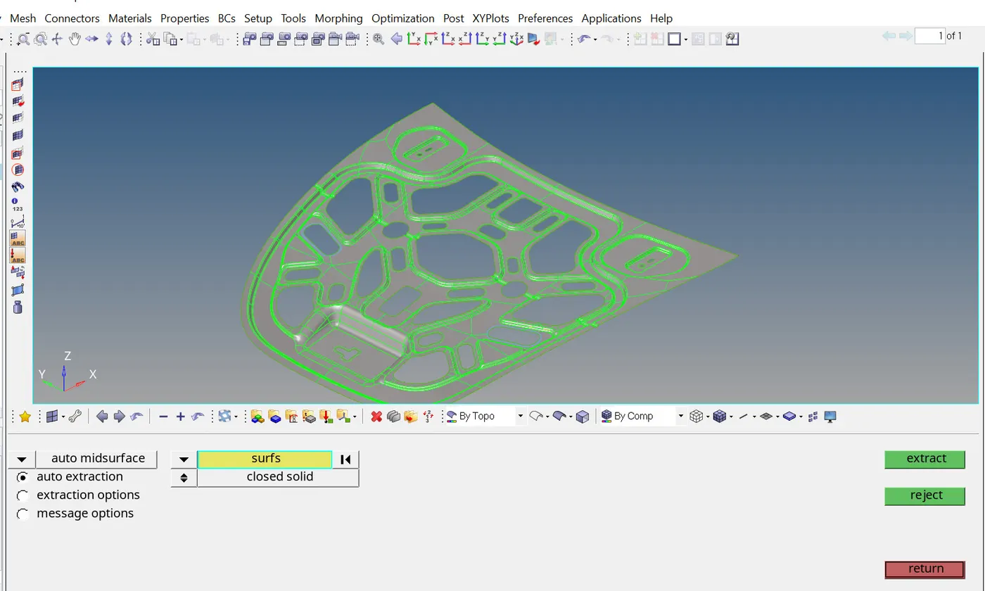
● Access the "Geometry" tab and locate the "Mid Surface" option.
● Choose the "Auto Mid" function to automatically generate mid-surfaces.
● Select the desired surface from the model to extract its mid-surface.
● Execute the extraction process and ensure the successful creation of the mid-surface.
● Go to the "Geometry" tab > Mid Surface > Auto Mid > Select surface > Extract.
4. Geometry Clean-up for Mid-Surface:
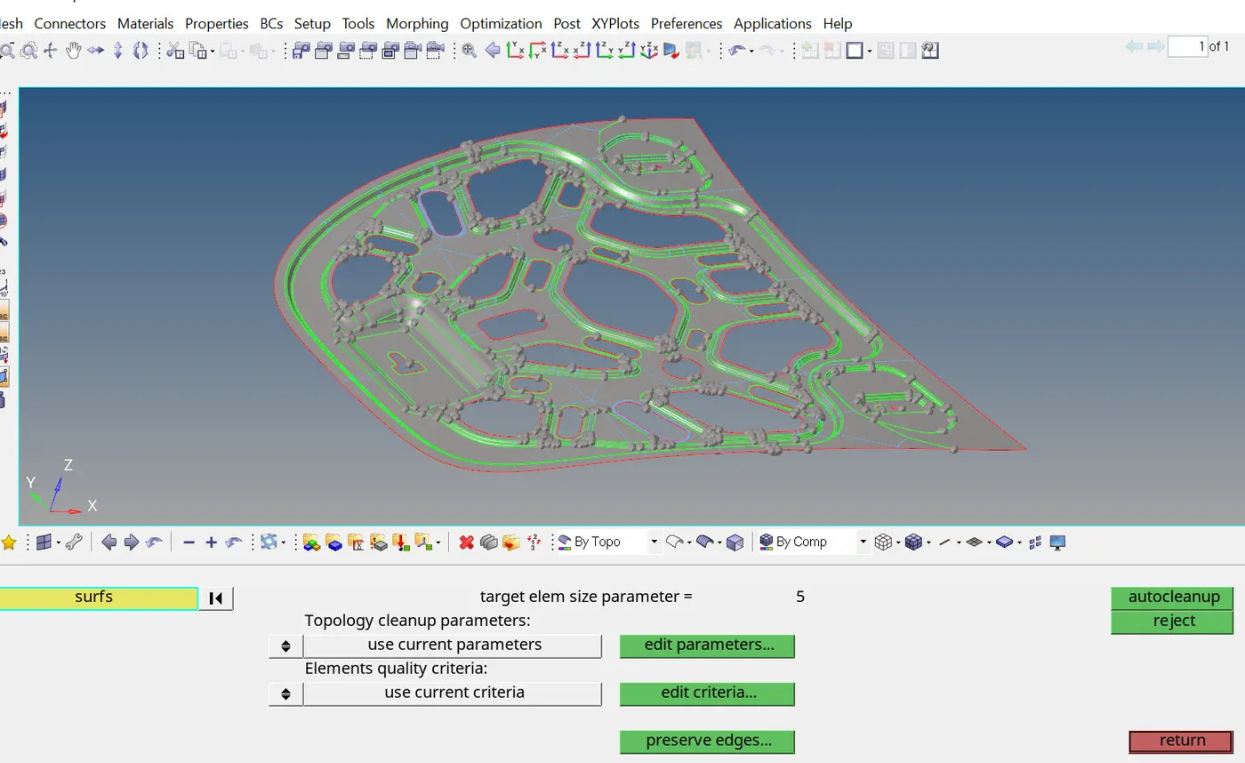
● Following the mid-surface extraction, proceed to the "Geometry" tab.
● Utilize the "Auto Clean Up" tool to perform cleanup operations on the extracted mid-surface.
● Review and address any irregularities or imperfections identified during the cleanup process.
● Confirm that the mid surface is optimized and ready for subsequent meshing operations.
● Go to the "Geometry" tab > Auto Clean Up > Review and address irregularities.
5. Add Quality Criteria Value in Criteria File Setting:
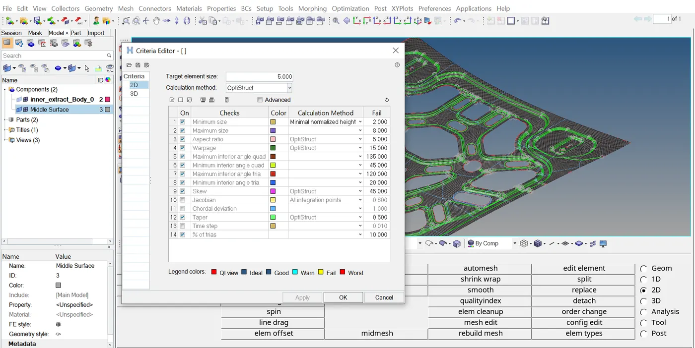
● Access the "Criteria File" settings within the software.
● Input the desired quality criteria values based on project requirements and specifications.
● Ensure that the criteria file is properly configured to guide the meshing process effectively.
● Save the updated criteria file to apply the specified quality standards during mesh generation.
● Go to the "Criteria File" settings > Input values > Save the file.
6. Meshing the Component:
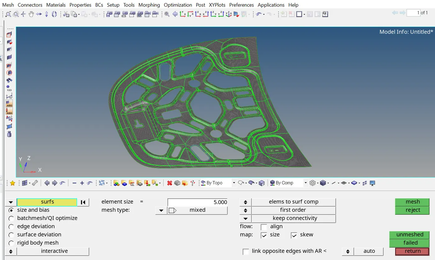
● Proceed to the "Mesh" tab and select the appropriate meshing method (e.g., 2D meshing).
● Choose the "Auto Mesh" option to initiate the meshing process.
● Select the previously extracted mid-surface as the target for mesh generation.
● Execute the meshing operation and verify the successful creation of the mesh for the component.
● Go to the "Mesh" tab > Select meshing method > Auto Mesh > Select surface > Mesh.
7. Check Mesh Quality Criteria:
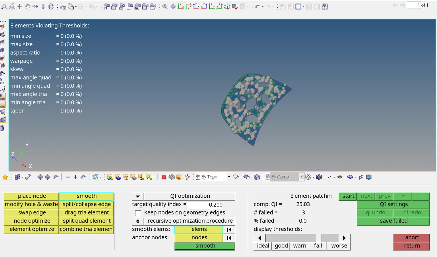
● Utilize the "Quality Index" tool to evaluate the quality of the generated mesh.
● Review the quality criteria metrics to identify any elements that fail to meet the specified standards.
● Analyze the results and determine areas where improvements or adjustments may be necessary.
● Take note of any failed elements for subsequent correction and refinement steps.
● Go to the "Quality Index" tool > Review results > Note failed elements.
8. Minimize Failed Elements and Correct:
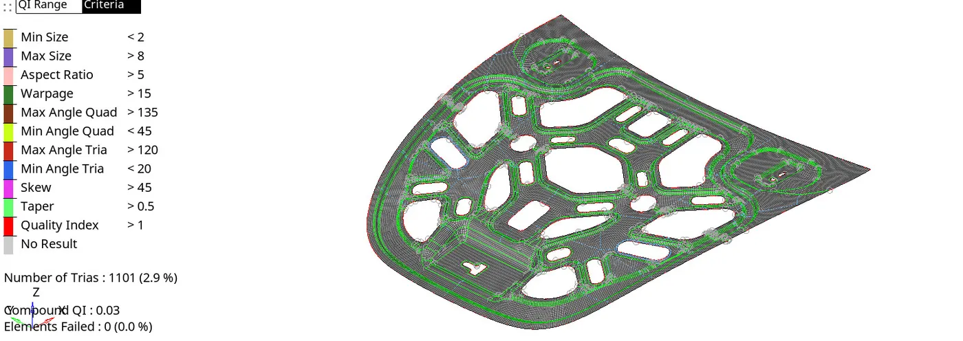
● Employ various mesh editing tools available in the software (e.g., Mesh Edit, Edit Element, Replace, Smooth, Element Clean Up) to address identified issues.
● Focus on minimizing the number of failed elements by applying appropriate corrective actions.
● Iterate through the correction process, refining the mesh as needed to achieve satisfactory results.
● Ensure that all mesh quality criteria are met before proceeding with further analysis or simulations.
Utilize mesh editing tools > Minimize failed elements > Refine mesh > Ensure criteria compliance.
> Finally mashed elements of the hood component look like shown below
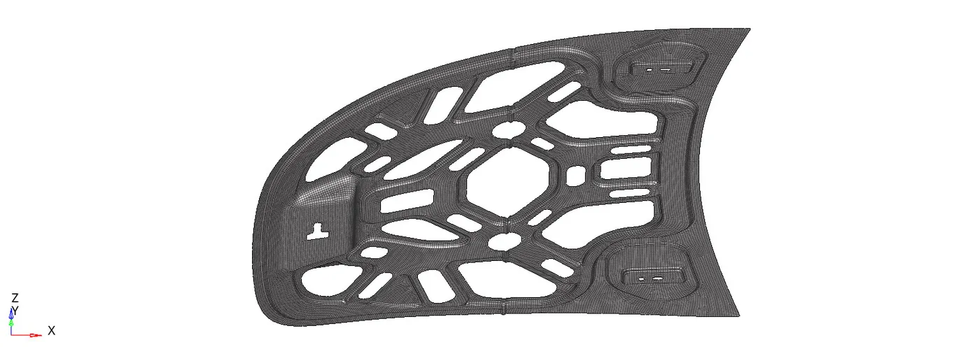
component file link
https://drive.google.com/file/d/1cm72nUXoD0H9OvJiW7XXI81TjzF_dQY0/view?usp=drive_link
conclusion
From this challenge, I've learned the essential steps of meshing complex components using HyperWorks software. Each stage, from solid deletion to mesh quality assessment, has emphasized the importance of precision and adherence to quality standards.