Week 3 - Geometry simplification of an Electronic enclosure assembly
Geometry Simplification Of An Electronic Enclosure Assembly
AIM: To create the workflow in the Ansys workbench and import the CAD model into Spaceclaim.
Objective:
- Use space claim commands to defeature the enclosure
- Use Icepack commands to convert CAD shapes into Icepak primitive shapes.
- Save converted geometry
- Open saved converted model into Icepak
- Check the geometry in icepak
- Modify components in icepak in order to define the correct physics.
Theory:
Types of bodies:
Focus bodies - The bodies which will emit some heat or obstruct the flow of the system.
Necessary bodies - The bodies which will have some effects on the focus bodies.
Peripheral bodies - These bodies may or may not affect the focus bodies.
Dispensable bodies - The small bodies on the assembly which has no effect on the physics of the system, these bodies are completely neglected.
Geometry simplification
We export the prepared geometry from CAD to SpaceClaim
The image attached below shows the given CAD geometry of an electronic enclosure.
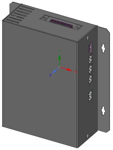
The following steps are taken to simplify/clean up the geometry so that it can be imported to Icepak:
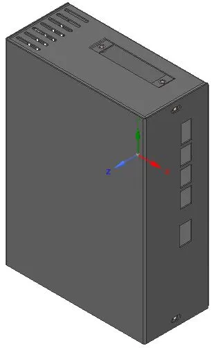
Since the extensions on the outer cover don't affect the flow or thermal analysis in any manner, they can be removed from the geometry using the Split Body command available in SpaceClaim.
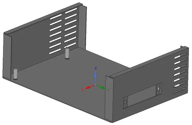
The bottom cover of the enclosure is opened in a separate design window. The image attached below shows the CAD geometry of the bottom cover.
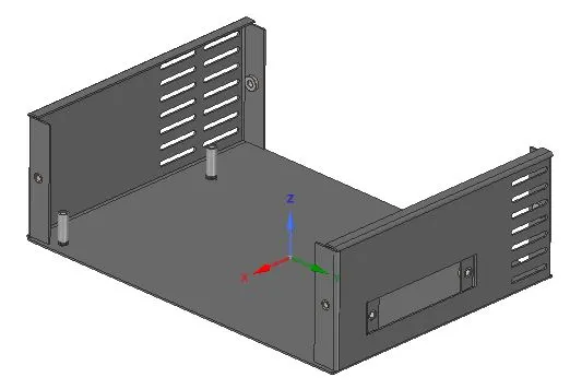
The following steps are used to convert the CAD geometry (shown above) into Icepak objects:
All the round edges and washers are removed from the geometry. All the holes present on the cover, for fasteners, are filled using the Fill command available in SpaceClaim.
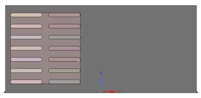
Openings are created using the Opening command and selecting the appropriate surfaces. Using these openings, the grilles are defined as shown in the images attached below.
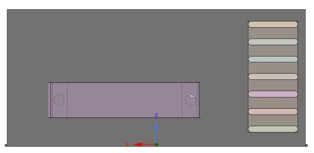
The geometry is then simplified into Icepak Objects using the Icepak Simplify command with Level 2 (polygon fit) simplification. The image attached below shows the bottom cover geometry simplified into Icepak Objects.

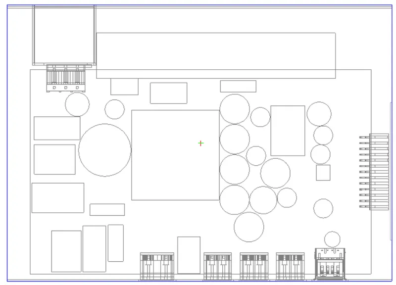
The part corresponding to PCB + electronic components is opened in a separate design window. The image attached below shows the part.
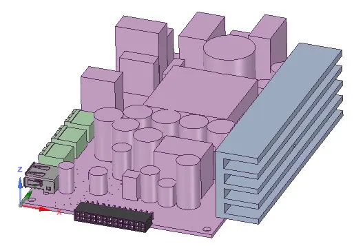
The following steps are used to simplify the CAD geometry (shown above) into Icepak Objects:
This part is divided into multiple parts by using the Split Body command with the top and bottom planes of the PCB. This separates most of the components from each other.
Identify Objects command is used to identify and convert CAD geometries of the bodies into Icepak Objects. The image attached below shows the different parts identified for conversion to Icepak Objects. (The parts are highlighted in red)
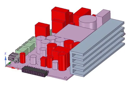
The remaining "Non-Icepak Bodies" are shown in the figure attached below.
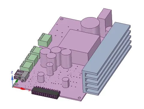
The PCB is simplified into Icepak Object using the Icepak Simplify command with Level 1 (cuboid, cylinder fit) simplification. The remaining "Non-Icepak Bodies" are shown below.
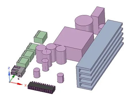
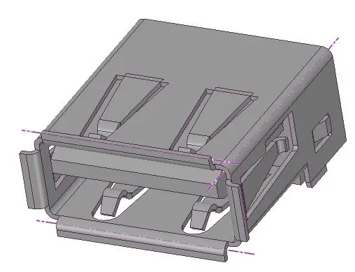
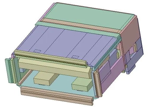
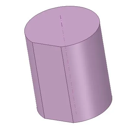
The remaining "Non-Icepak Bodies" are simplified using Level 1 (cuboid, cylinder fit) or Level 2 (polygon fit) simplification. Some of the bodies are separated into multiple bodies using the Split Body command and selecting appropriate planes. The images attached below show some of the bodies before and after simplification.
(a) CAD geometry (before simplification)
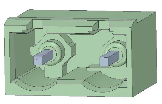
(b) Icepak Object (after Level 2 (polygon fit) simplification)
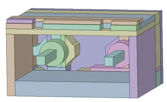
(a) CAD geometry (before simplification)
(b) Icepak Object (after Level 2 (polygon fit) simplification)
(a) CAD geometry (before simplification)
(b) Icepak Object (after Level 2 (polygon fit) simplification)
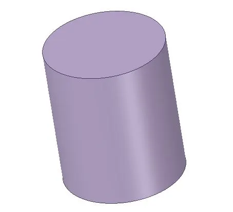
(a) CAD geometry (before simplification)
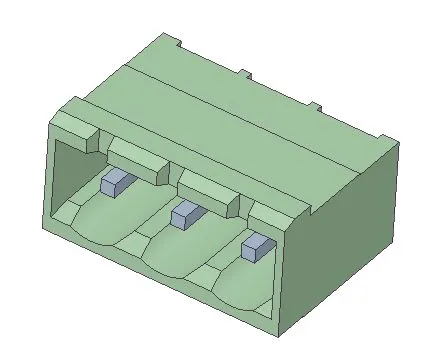
(b) Icepak Object (after Level 2 (polygon fit) simplification)
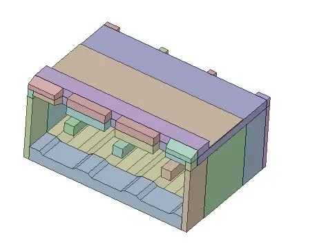
(a) CAD geometry (before simplification)
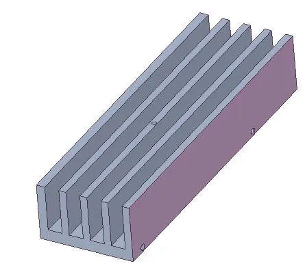
(b) Icepak Object (after Level 2 (polygon fit) simplification)
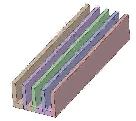
(a) CAD geometry (before simplification)
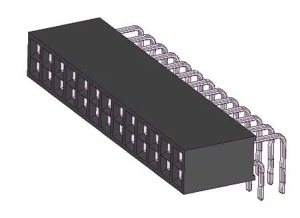
(b) Icepak Object (after Level 2 (polygon fit) simplification)
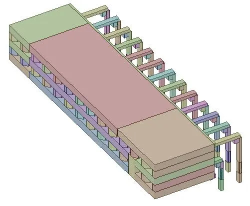
The image attached below shows the CAD geometry, consisting of PCB and electronic components, simplified into Icepak Objects.
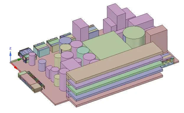
The remaining "Non-Icepak Bodies" are shown in the image attached below.
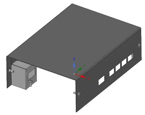
The following steps are used to simplify the CAD geometry (shown above) into Icepak Objects:
All the round edges, washers, and screws are removed from the geometry. All the holes present in the geometry which don't allow air to flow in or out of the enclosure are filled using the Fill command.
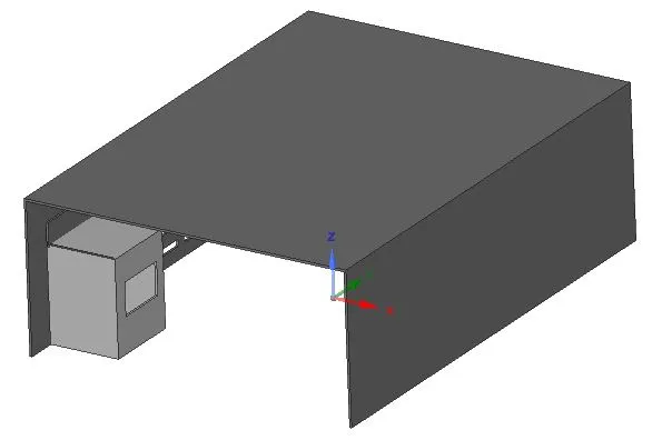
Openings are created using the Opening command and selecting the appropriate surfaces.
4.3. Grilles are created using the Grille command and selecting appropriate openings as shown in the image attached below.
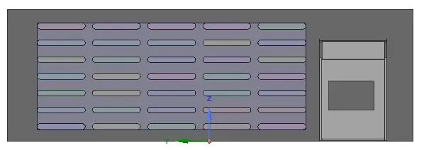
4.4. The part corresponding to the top cover of the enclosure is simplified into Icepak Objects using the Icepak Simplify command with Level 2 (polygon fit) simplification.
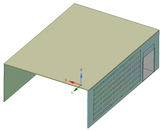
4.5. The remaining "Non-Icepak Objects" are shown in the image attached below.
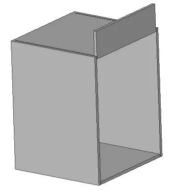
The CAD geometry (shown above) is simplified into Icepak Objects using the Icepak Simplify command with Level 2 (polygon fit) simplification.
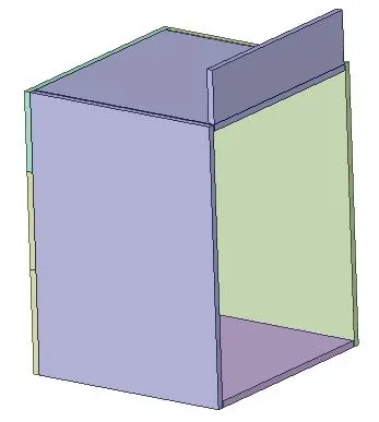
Upon following the steps outlined above, the entire CAD geometry is simplified into Icepak Objects as shown in the image attached below.
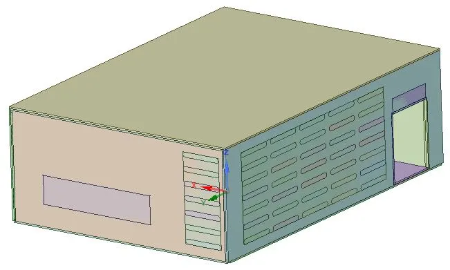
After simplification, the geometry is saved as an Icepak project. A workflow with the following two standalone systems is created in ANSYS Workbench:
A. Geometry
B. Icepak
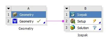
The two standalone systems are linked such that the geometry imported/created/simplified in the Geometry tab of the system A (Geometry) is transferred to the Setup tab of the system B (Icepak). The image attached below shows the workflow created in ANSYS Workbench.
Upon opening the Setup tab of system B (Icepak), the simplified CAD geometry is loaded into Icepak. The image attached below shows the simplified CAD geometry in Icepak.
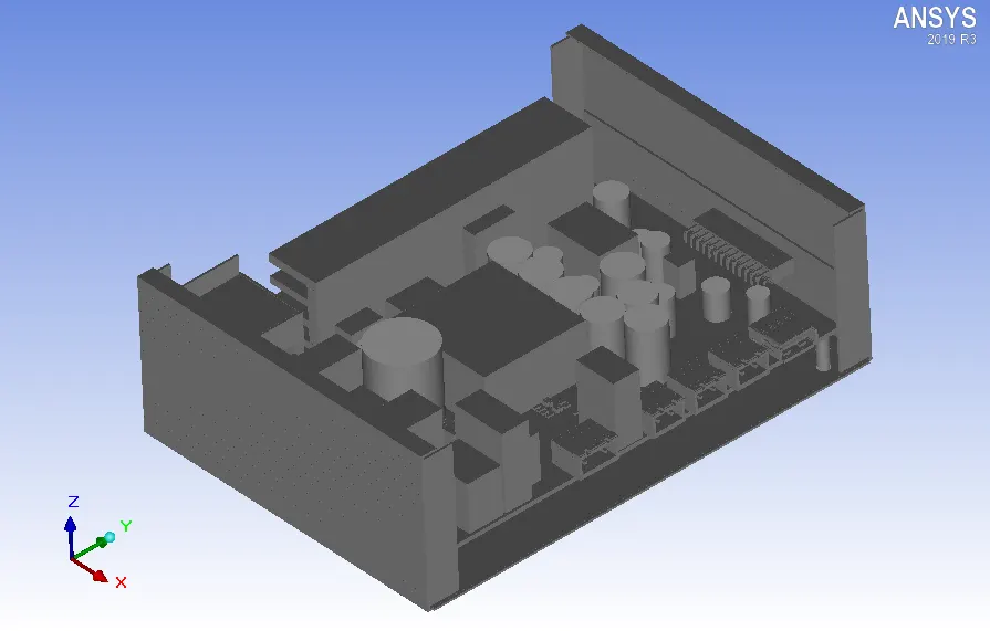
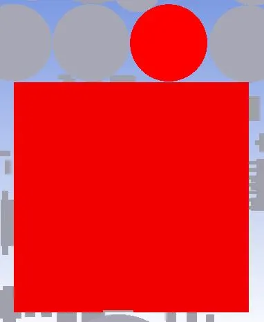
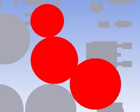
Before the computational domain is meshed, certain checks are performed to ensure that the correct physics is defined. One such check is the interference check in which the geometries interfering with each other are identified, either manually or using Macros. In order to pass this check, the interfering geometries are moved apart manually in Icepak. The images attached below show some examples.
1.
Interfering geometries
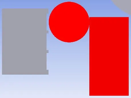
Non-interfering geometries
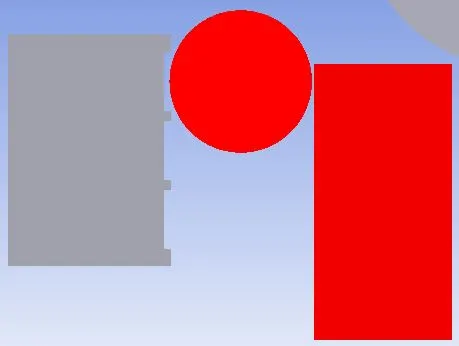
2.
Interfering geometries

Non-interfering geometries

3.
Interfering geometries
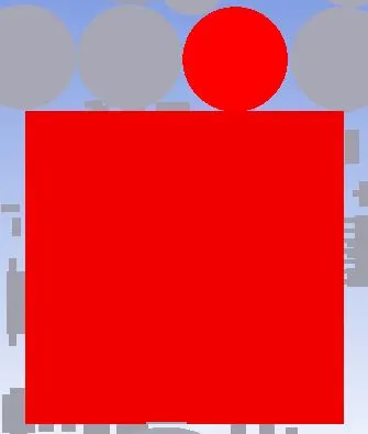
Non-interfering geometries
4.
Interfering geometries

Non-interfering geometries

5.
Interfering geometries
Non-interfering geometries

After the interfering geometries are moved apart from each other manually in Icepak, the Macros Automatic Case Check Tool is applied. The image attached below shows the output of the Macros.
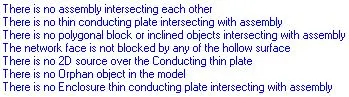
As evident from the output of the Macros, there are no remaining intersections in the geometry. Now, the geometry is ready for meshing.