Week 3: Flow over a backward facing step
AIM
We have to simulate a flow over a backward facing step on converge for plots of velocity, pressure, mass flow rate and total cell count with different mesh sizes
INTRODUCTION
Backward Facing Step (BFS) flow is one representative model for separation flows, which can be widely seen in aerodynamic flows (aerofoil, spoiler, high angle process), engine flows, condensers, vehicles, heat transfer system and even the flow around buildings etc. The Backward-Facing Step (BFS) flows, is also called as “sudden expansion flows”, “circular expanding flow”, “back-step flow”, “diverging channel” or “backward flow” under some other occasions, involves the basic features of general separation flows. It has three-dimensional nature and suitable for two-dimensional discussions under some flow conditions and/or with simple step geometry. BFS generally includes an inflow with uniform velocity (laminar or turbulent) from a channel (height H), a step on the lower side (or upper side, or both sides) with a step height of h. The flow field of BFS is also generally divided into four regions: separated shear layer, the recirculation region under the shear layer, the reattachment region, and the attached/recovery region.
Fig 1. Schematic of BFS flow evolutions
Fig 2. Concept model for BFS control
Basic geometric and physical model of Backward-Facing Step (BFS) flow are shown. BFS generally includes an inflow with uniform velocity (laminar or turbulent) from a channel (height H), a step on the lower side (or upper side, or both sides) with a step height of h. The flow field of BFS is also generally divided into four regions: separated shear layer, the recirculation region under the shear layer, the reattachment region, and the attached/recovery region. From the viewpoint of a flow dynamics, the BFS flow happens with large separation vortices in the backward step region and with some small vortex in the corner. Sometimes complex vortex series will also happen under different Re and geometric conditions.Between the separation bubble and the mainstream flow a free shear layer can be found, slight different from that of a plane shear layer due to the existence of separation bubble. The shear layer then develops and finally form re-attachment on downstream boundary.
This project deals with Backward Facing Step (BFS) geometry setup for three different mesh sizes:
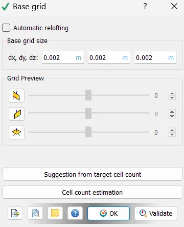
- CASE 1: Base Mesh size = 2.0 e-3m
- CASE 2: Base Mesh size = 1.5e-3 m
- CASE 3: Base Mesh size = 1.2e-3 m
CASE SETUP
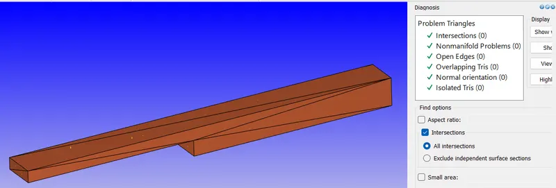
STEP 1) Diagnose and correct the geometry fot backward step geometry
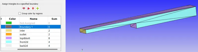
Step 2) Define all the boundaries of geo as it should be
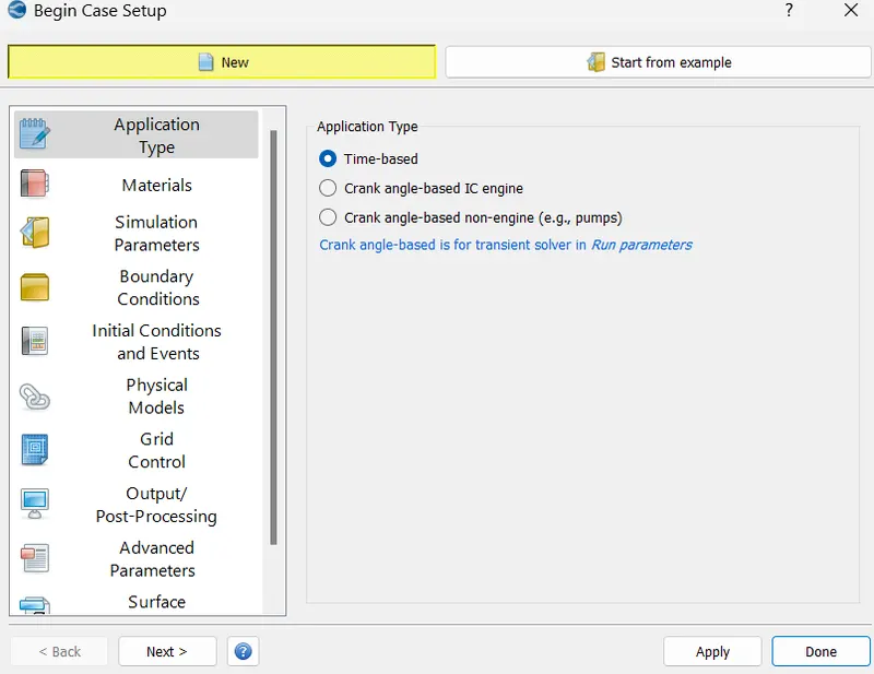
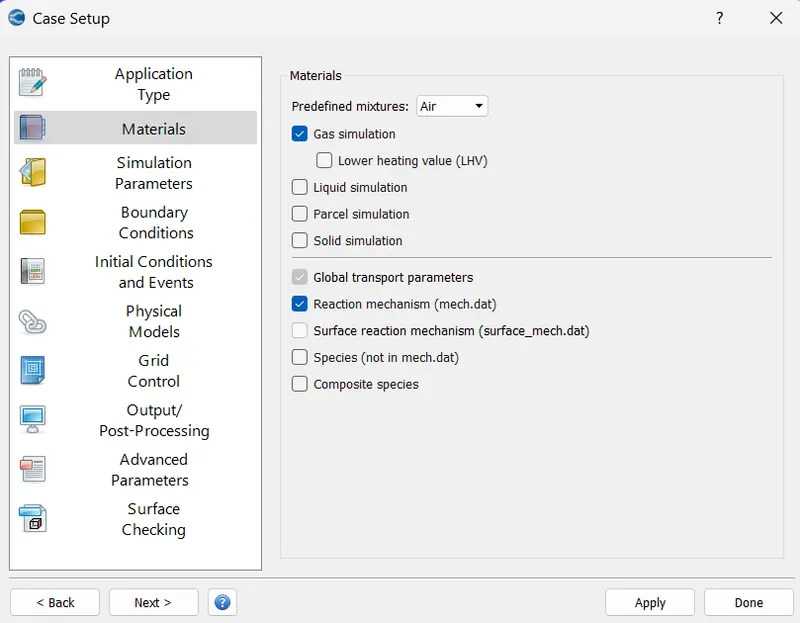
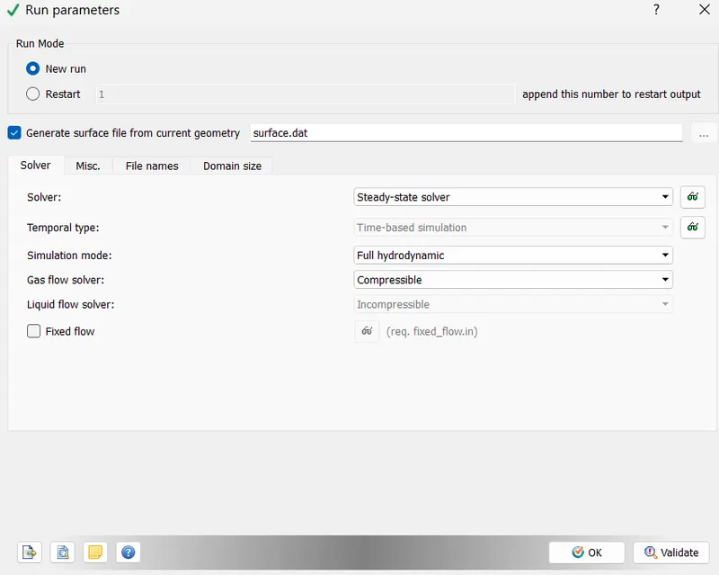
Step 3) Start with seting up the case
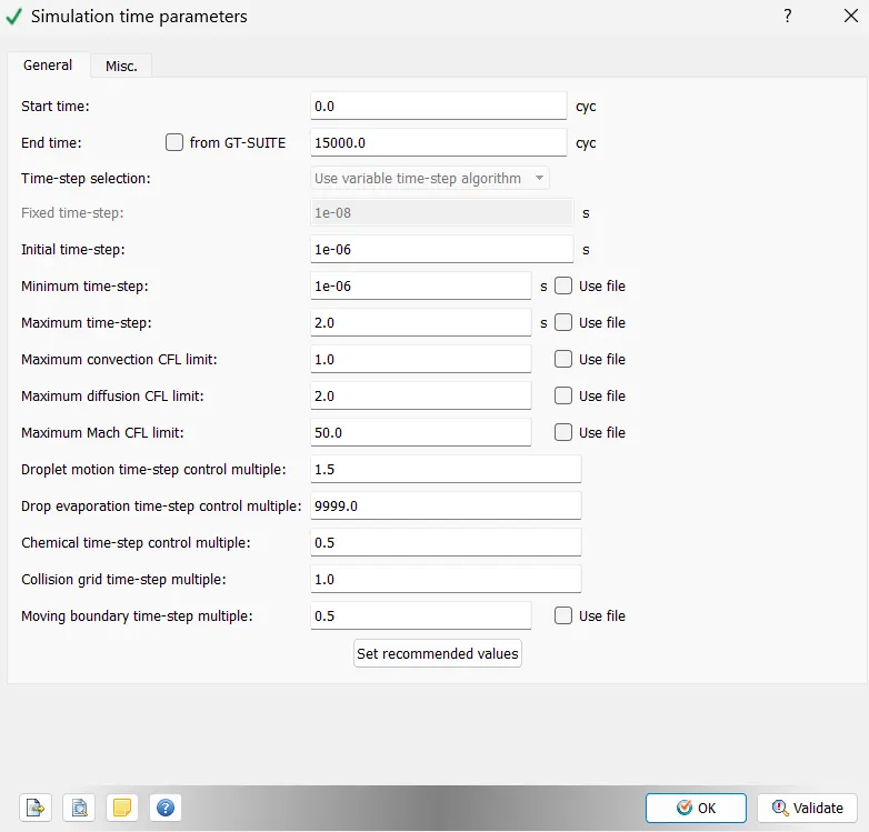
Step 4) Define the time related parameters
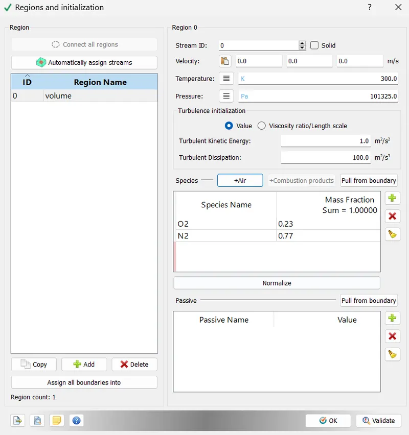
Step 5) Define and name the regions
Step 5) Give mesh element length for meshing
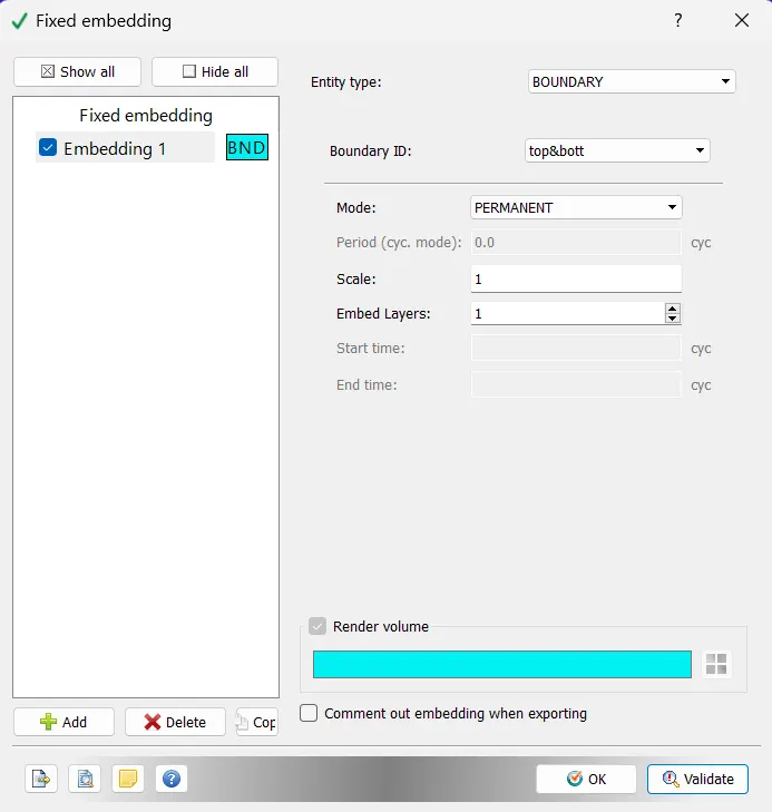
Step 6) Export the setup parameters to new folder and run them through cygwin
RESULT
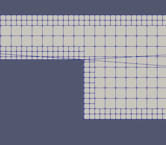
Case 1 Mesh - 2mm
Mesh
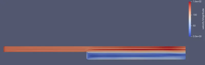
Velocity Profile & Plot
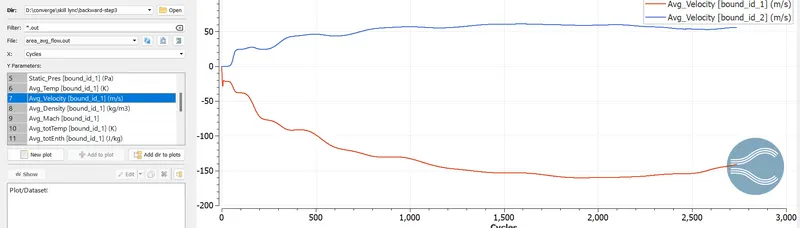
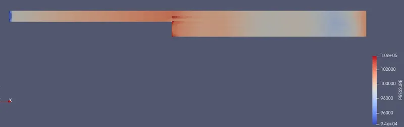
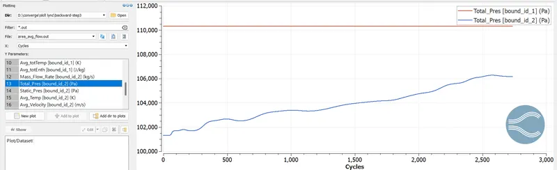
Pressure Profile & Plot
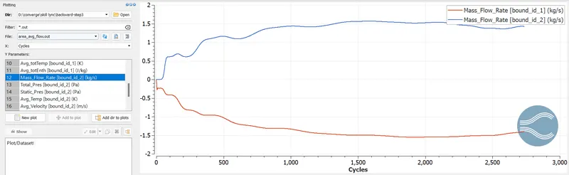
Mass-flow rate
Case 2 Mesh -1.5mm
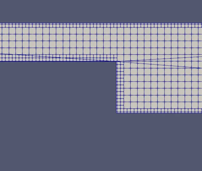
Mesh
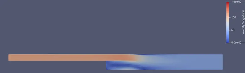
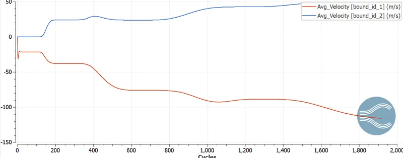
Velocity Profile & Plot
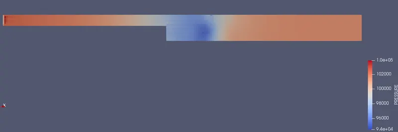
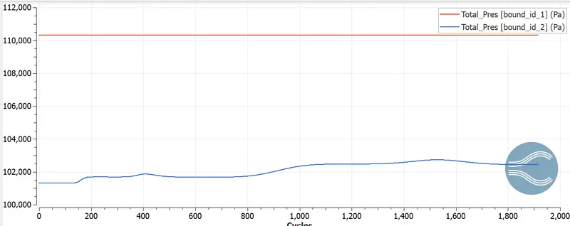
Pressure Profile & Plot
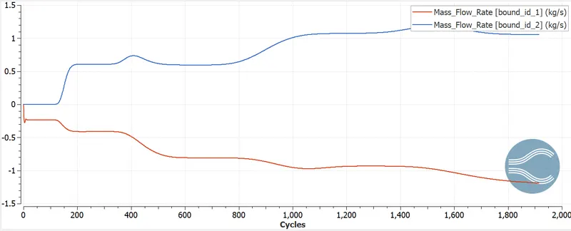
Mass flow rate
CONCLUSION
From the above results we can obtain the following points :-
Decrese in mesh size results in increase of grid points and the accuracy.
Steady state is achieved in all cases after few cycles.
The velocity decreases and pressure increases at flow seperation region after the backward step.
We can notice thee parabollic profile of velocity of flowing fluid that exist due to surface friction.
ANIMATION