Week 3 - External flow simulation over an Ahmed body.
AIM:
To do a external flow simulation over an Ahmed body
OBJECTIVE:
Q1. Describe Ahmed's body and its importance.
Q2. Explain the reason for the negative pressure in the wake region.
Q3. Explain the significance of the point of separation.
EXPECTED RESULTS:
- Velocity and pressure contours.
- The drag coefficient plot for a refined case. (For velocity of 25m/sec, the drag coefficient should be around 0.33).
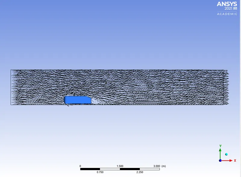
- The vector plot clearly showing the wake region.
- Perform the grid independency test and provide the values of drag and lift with each case.
Q1. DESCRIBE AHMED BODY AND ITS IMPORTANCE.
The Ahmed body is a benchmark model widely used in the automotive industry for validating simulation tools. The Ahmed body shape is simple enough to model, while maintaining car-like geometry features. This body allows us to capture all the characteristics features that are relevant to bodies in the vehicle industry. A lot of studies can be performed using the geometry like calculating drag, lift forces on the vehicle, studying the presence of vortices and wake region behaviour at different slant angles at the back of the vehicles.
Q2. EXPLAIN THE REASON FOR THE NEGATIVE PRESSURE IN THE WAKE REGION.
The wake region is a disturbed flow region around a solid body moving through a fluid. This is caused due to the boundary layer separation which creates a high turbulent flow zone. The velocity and pressure in the region are low and increases the drag force on the body. Therefore the formation of wake region is one of the important characteristics to consider while designing an automobile.
Q3. EXPLAIN THE SIGNIFICANCE OF THE POINT OF SEPARATION.
The point of separation is a point where the fluid flow no longer follows the contour of the body and gets detached from the surface of the body. When there is a fluid flow over a solid body there is a retarding effect on the fluid flow because of shear stress between fluid and solid body. This gives rise to the negative pressure gradient and the fluid flow detaches from the surface giving rise to vortices and eddy forces. Once the fluid is detached it exerts constant pressure on the surface instead of exerting a continually increasing pressure.
Y+:
Y+ is a non-dimensional distance which is used to describe how coarse or fine a mesh is for a particular flow pattern. It is important in turbulence modelling to determine the proper size of the cells near domain walls. The turbulence model wall laws have restriction on the y+ value at the wall.
Density, rho = 1.225
Velocity, U = 25m/s
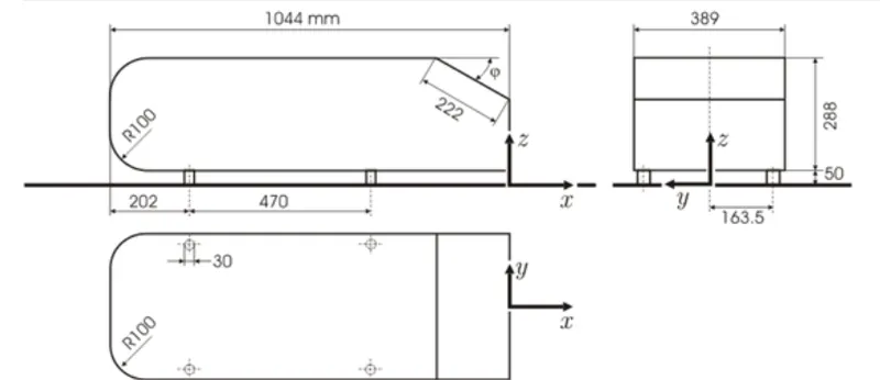
Length, l = 1.044 m
Viscosity, mu = 1.79*10^(-5) pa.s
REYNOLDS NUMBER, re = (rho.U.l)/mu
Reynolds number @ 25m/s = 1.7862e+06
SETUP:
DIMENSIONS:
GEOMETRY:
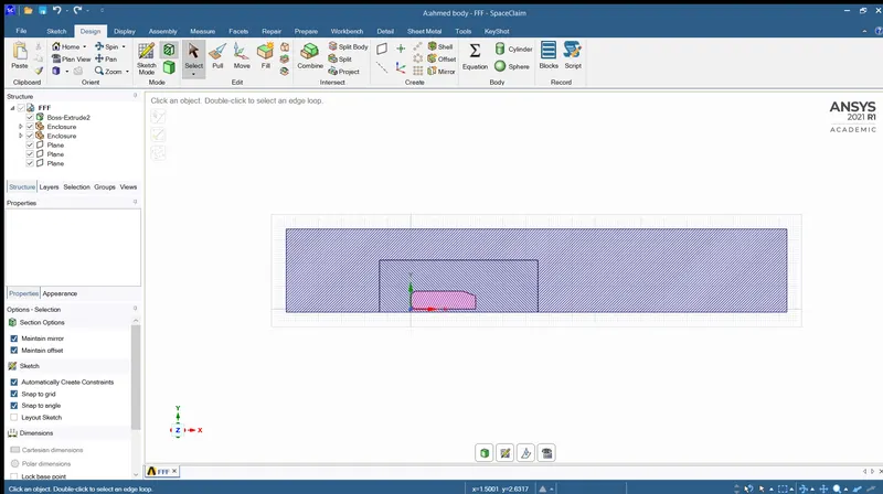
First an enclosure is prepared around the Ahmed body to create a domain where fluid will flow on the body. Enclosure is just all the domain minus the Ahmed body. Another enclosure is prepared around the Ahmed body which contains the Ahmed body more closely.
GENERATING MESH:
Method used – multizone
MULTIZONE:
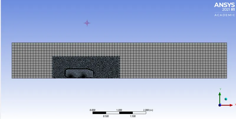
The outer enclosure is provided with hexahedral meshes. Hexahedral meshes are the ones which are better than tetrahedral meshes, but it doesn’t fits for complex geometries but has this is a simple geometry we can use hexahedral mesh.
Multizone creates a hexahedral mesh wherever possible.
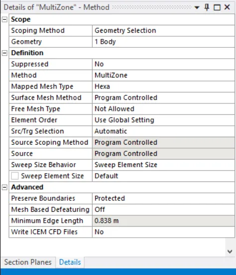
The mesh size of 100mm is used for larger enclosure.
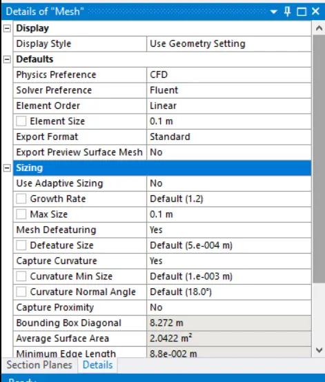
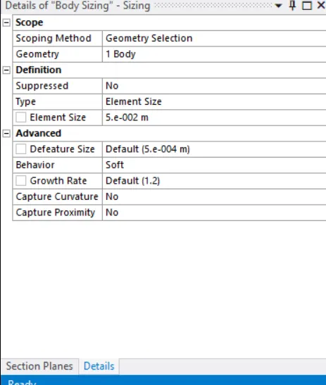
Inner enclosure will have the base line tetrahedral mesh, the element size of the mesh is reduced using the sizing option and hence a element size of 50mm is used for the meshes of inner enclosure.
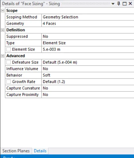
The face sizing for 5mm is used for the circles openings at the bottom of Ahmed body.
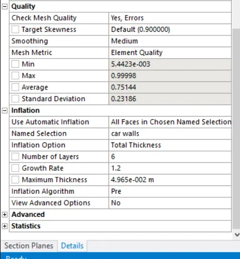
The inflation layer is used to refine the local region just above the wall/body to capture the boundary layer precisely.
The 6 inflation layer of total thickness 49.6496mm is created around the car wall.
The generated mesh will be looks like the image as shown below.

The above figure shows the proportion of tetra, hex, wedge and pyramid type of mesh under the multizone meshing type. This plot shows the minimum mesh metric criterion.
SETUP:
|
SOLVER TYPE |
Pressure based |
|
VELOCITY FORMULATION |
Absolute |
|
TIME |
Steady |
|
VISCOUS MODEL |
Standard K-epsilon with standard wall function |
|
MATERIAL |
Fluid - air |
|
CELL ZONES |
Dynamic viscosity – 1.79e-5 kg/ms |
|
BOUNDARIES |
Velocity magnitude 25m/s
Gauge pressure – 0 pa
No slip (condition) |
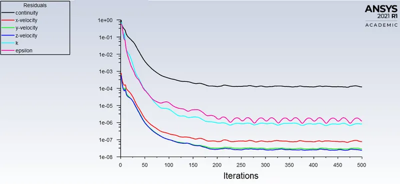
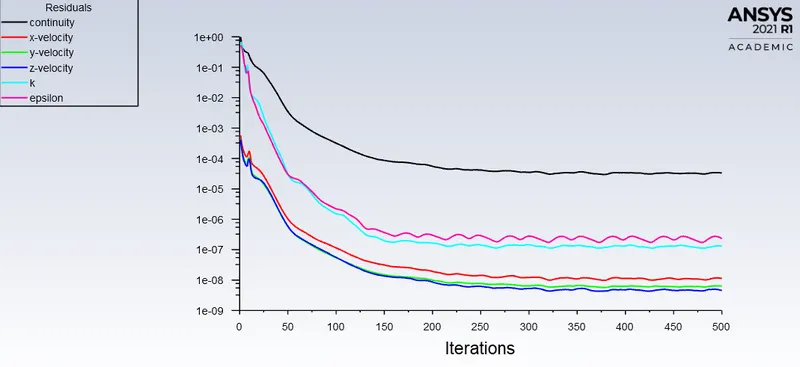
The model was initialized using hybrid initialization with 500 iterations to run the simulation.
RESULTS:
RESIDUAL:
VELOCITY CONTOUR:
PRESSURE CONTOUR:
VECTOR PLOT:
DRAG PLOT AND LIFT PLOT:
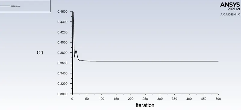
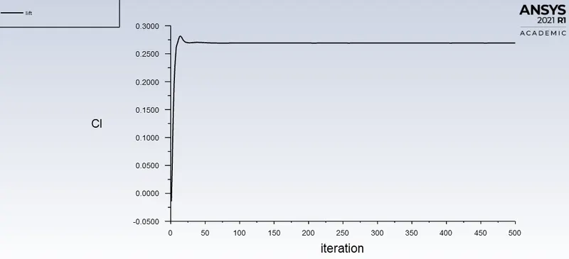
The coefficient of drag value for this case comes out to be 0.36329838 which is much considerable as our aim was to get the value around 0.33. similarly the coefficient of lift value comes out to be 0.26910341.
CHART:
GRID DEPENDENCY TEST:
Mesh size for outer enclosure = 75mm, Mesh size for inner enclosure = 4mm
RESIDUAL:
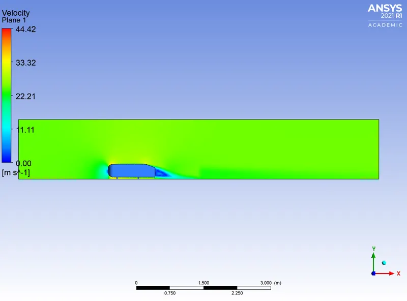
VELOCITY CONTOUR:
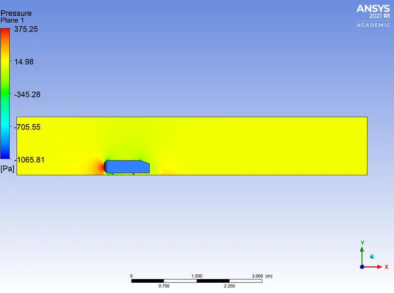
PRESSURE CONTOUR:
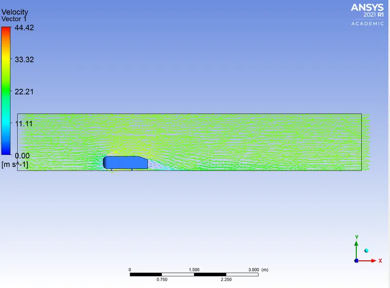
VECTOR PLOT:
DRAG PLOT AND LIFT PLOT:
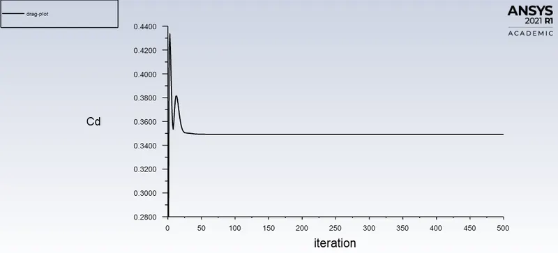
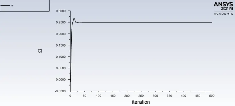
The coefficient of drag value for this case comes out to be 0.34920554 which is much considerable as our aim was to get the value around 0.33. similarly the coefficient of lift value comes out to be 0.24975126.
CHART:
Mesh size for outer enclosure = 75mm, Mesh size for inner enclosure = 3.5mm
RESIDUAL:
VELOCITY CONTOUR:
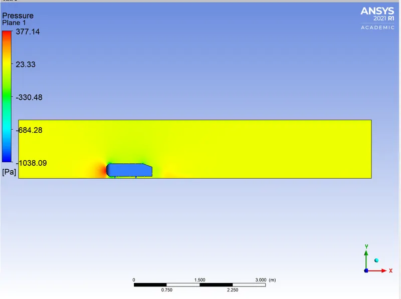
PRESSURE CONTOUR:
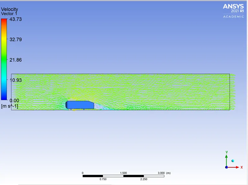
VECTOR PLOT:
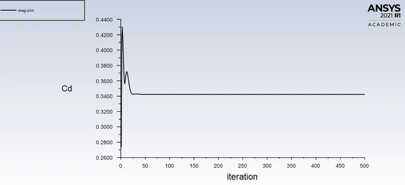
DRAG PLOT:
LIFT PLOT:
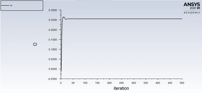
The coefficient of drag value for this case comes out to be 0.34224701 which is much considerable as our aim was to get the value around 0.33. similarly the coefficient of lift value comes out to be 0.25515115.
CHART:
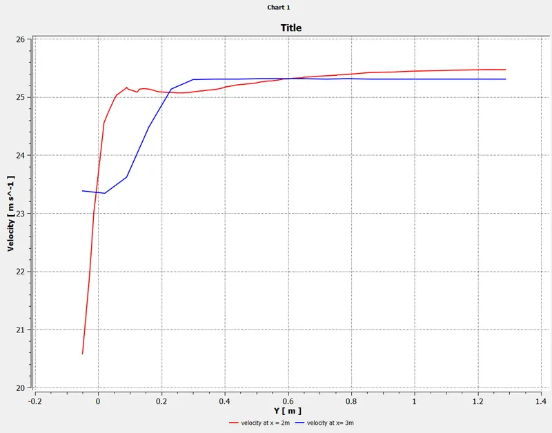
SUMMARY:
|
MESH SIZE OF OUTER ENCLOSURE |
MESH SIZE OF INNER ENCLOSURE |
DRAG |
LIFT |
|
100mm |
5mm |
0.36329838 |
0.26910341 |
|
75mm |
4mm |
0.34920554 |
0.25515115 |
|
75mm |
3.5mm |
0.34224701 |
0.24975126 |
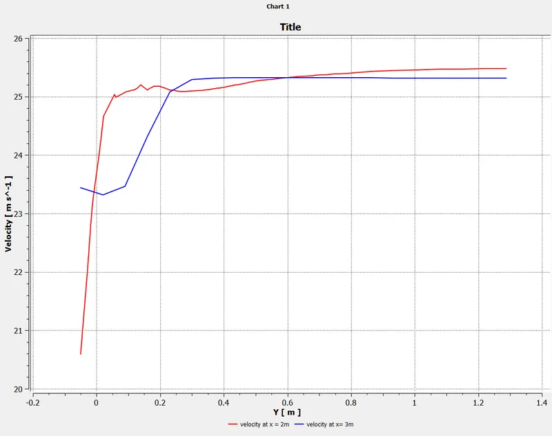
from the above table we can say that on decreasing the mesh size the drag and lift both decreases and we get the more accurate results however it increases the computational time.
CONCLUSION:
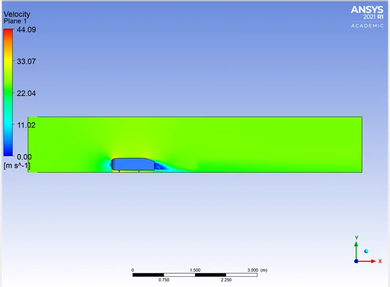
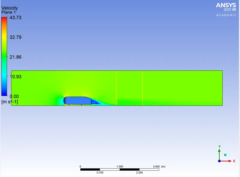
- We observed a wake region have established at the rear side of the ahmed body in velocity flow, which have created a vortex flow at rear side. In that wake region, a negative pressure have been originated. This is because of recirculation region that have been developed at the rear side of the Ahmed body.
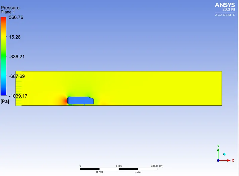
- Due to flow separation behind the ahmed body we observe negative pressure in that area. The viscosity and the pressure gradient plays a major role in the generation of negative pressure in the wake region.
- We can also see two small recirculation zones at curve edge of front and slant edge of the ahmed body in pressure profile known as point of separation. The point of separation occurs due to turbulence in the region and leads to deattachment of flow which causes a sudden drop in stream velocity in wake region.