Week 3 - External flow simulation over an Ahmed body.
EXTERNAL FLOW SIMULATION OVER A AHMED BODY
AIM: To run external flow simulations over an Ahmed body with the given conditions
OBJECTIVE:
Answering the following questions:
Q1. Describe Ahmed's body and its importance.
Q2. Explain the reason for the negative pressure in the wake region.
Q3. Explain the significance of the point of separation.
Expected Results:
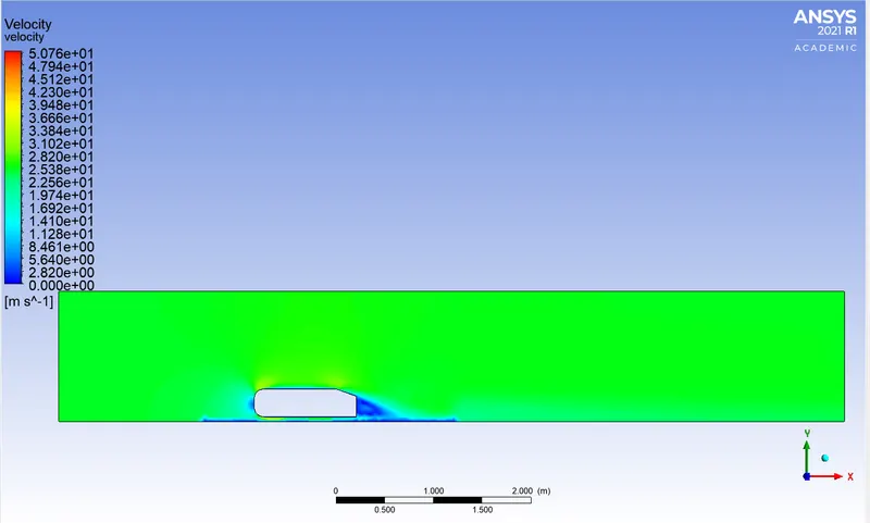
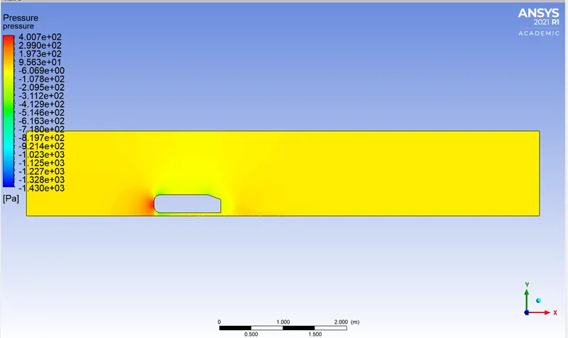
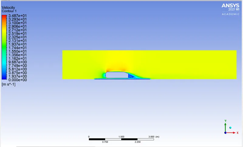
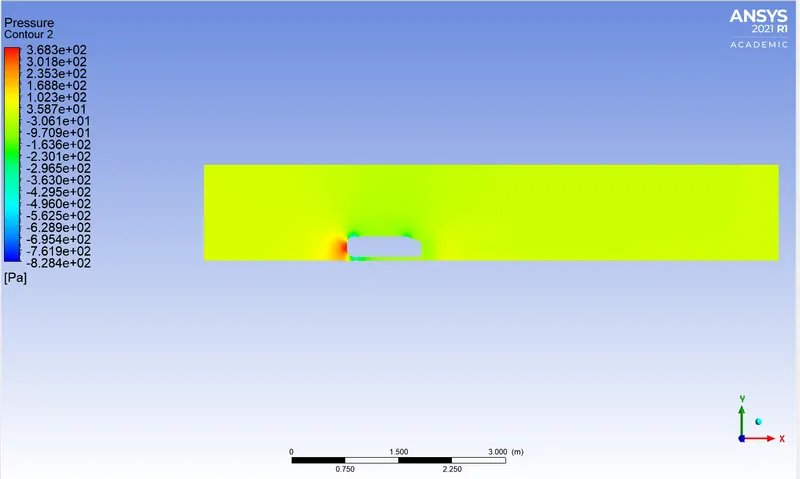
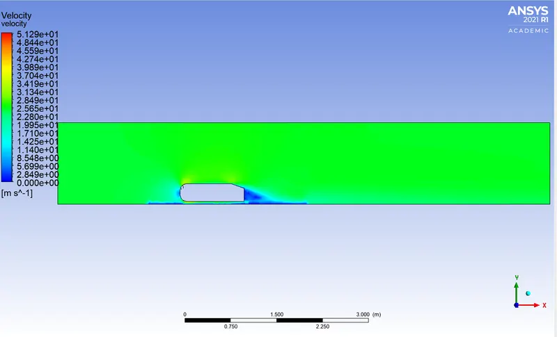
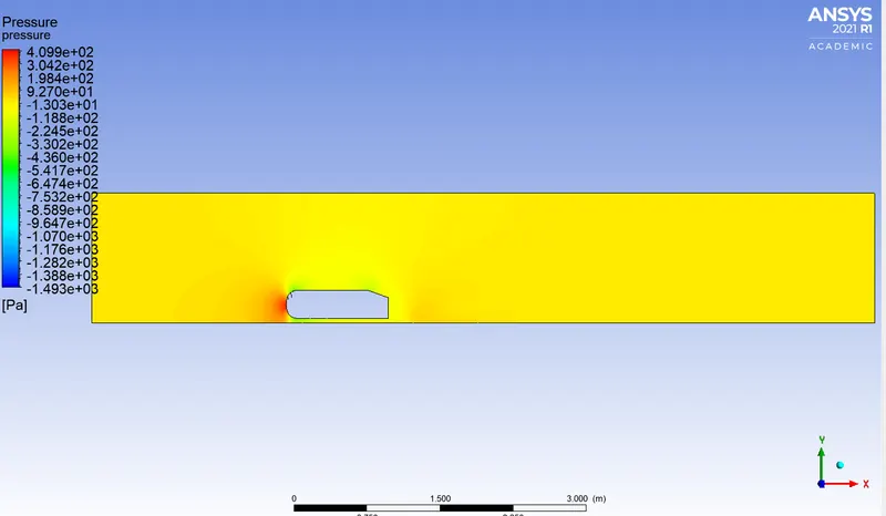
1. Velocity and pressure contours.
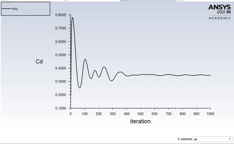
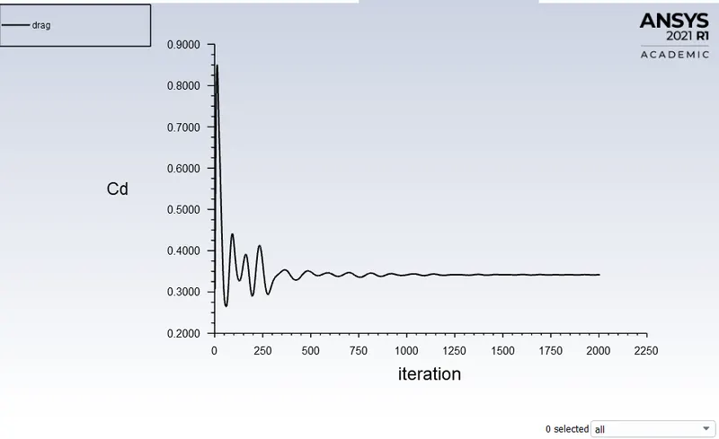
2. The drag coefficient plot for a refined case. ( For a velocity of 25m/sec, the drag coefficient should be around 0.33).
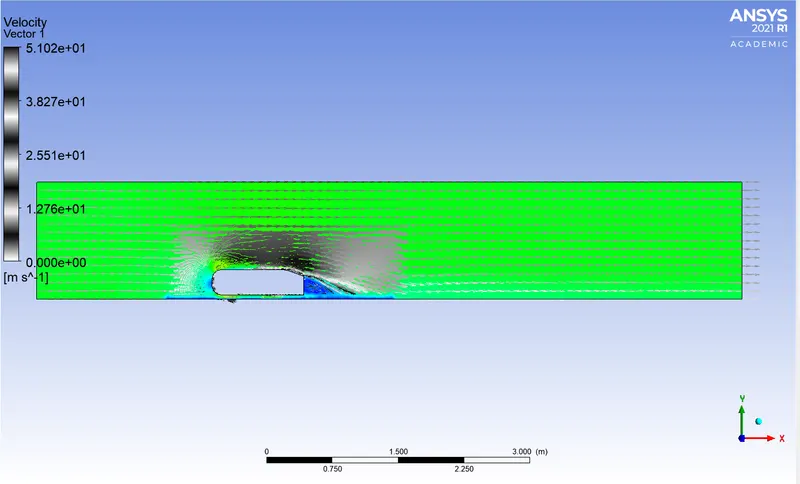
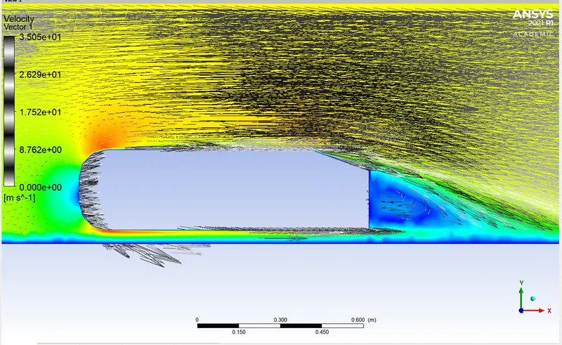
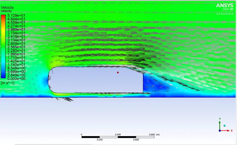
3. The vector plot clearly showing the wake region.
4. Perform the grid independence test and provide the values of drag and lift with each case.
THEORY:
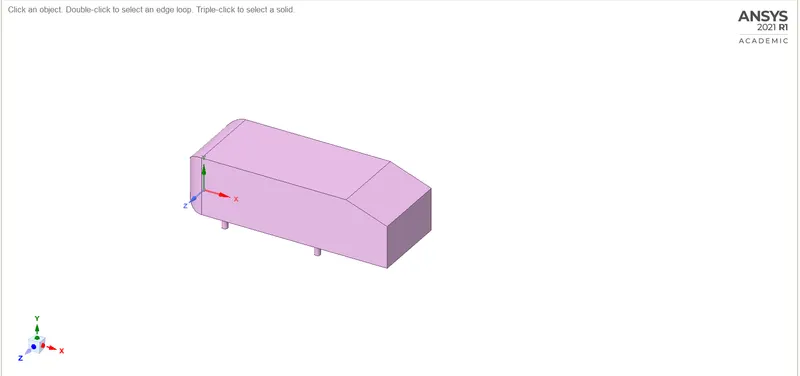
Ahmed body: The Ahmed body was first created by S.R. Ahmed. It is an important benchmark for aerodynamic simulation tools. It will be clearly shown in the sketch below that it has a length of 1.044 meters, a height of 0.288 meters, and a width of 0.389 meters. It also has 50-millimeter cylindrical legs attached to the bottom of the body and the rear surface which has a slant that falls at 35 degrees.
The flow for the model is turbulent which is based on velocity and body length. For the default mesh size in ANSYS-FLUENT we will use the `k-epsilon` model and for the later stage `k-omega`SST model is used.
Importance of Ahmed body
The drag force is an important factor considering fuel consumption. As the drag force increases the fuel consumption also increases which in turn becomes expensive for the car owners. As the burning of fossil fuels becomes an issue, the manufacturers are pressing for fuel-efficient cars. One of the main factors considering the car is fuel-efficient or not is the car's geometry.
Complex-shaped cars are very challenging to model and it's difficult to quantify the aerodynamic drag computationally. The Ahmed body is a benchmark model widely used in the automotive industry for validating simulation tools.
Negative pressure in the wake region
When the air moving over the vehicle is separated at the rear end, it leaves a large low-pressure turbulent region behind the vehicle which is known as the wake. This contributes to the formation of pressure drag which affects the vehicle performance.
When the vehicle is moving at a certain velocity the fluid imparts viscous force to the vehicle as long as it is in the viscous sublayer of the boundary. When the fluid reaches the rear end of the vehicle it gets detached from the surface of the body causing negative pressure in the wake region. The movement of the fluid around the vehicles depends on the geometry of the car and the Reynolds number.
Significance of point of separation
The point of separation will occur when there is a discontinuity in the surface or a region of the negative pressure gradient.
When the flow is attached to the body of the vehicle the viscous force will increase which will increase the pressure and a decrease in velocity before the rear end of the vehicle. As soon as the air encounters the sharp turn causing the velocity decreases resulting in the negative pressure region which is in the wake region. The recirculation region happens beyond the point of separation. If the rate of change of pressure is large the mixing process will not occur and the boundary layer flow stops. The above figure shows that at the point of turning the flow gets separated from the boundary layer and there is a region of recirculation after which the flow attaches itself to the boundary layer. In order to reduce the separation of fluid from the boundary layer, it is advisable to have a smooth edge to reduce the effect of drag on the vehicle.
Y plus Value:
The Y+ values are a non-dimensional distance from the wall to the first mesh node, as shown below figure. To use a wall function approach for a particular turbulence model with confidence, we need to ensure that our y+ values are within a certain range.
It's important to ensure Y+ values are not so large that the first node falls outside the boundary layer region. If this happens, then the wall functions used by the turbulence model may incorrectly calculate the flow properties at this first calculation point which will introduce errors into pressure drop and velocity results.
Reynolds number, Re = `(rho VL)/mu`
As we know inlet velocity V= 25m/s and material is air with density 1.225
`Re = (1.225xx25xx1.044)/(1.7894xx10^-5)`
`:. Re = 1786772.10`
`Cf =(0.0576)/((Re)^(1/5)`=0.00326
`Tomega = (Cfxxrhoxxv^2)/2`
`:.Tomega=(0.00326xx1.225xx25^2)/2`
`:.Tomega =1.24796N/(m^2)`
`u_f = sqrt((Tomega)/(rho)``:. u_f=sqrt(1.24796/1.225) = 1.009327m/s`
as we consider y+ value 5
hence first layer thickness,
`y1=(vy^+)/(rhou_f)`
`y1=(1.7894xx10^-5xx5)/(1.225xx1.009327)`
`y1=0.0716483`
SOLUTION AND RESULTS
This Project has a total of 3 cases as per the 4th question to run the independence test. These cases differ based on their Meshing part leaving the rest the same for all the cases.
Geometry:
The basic Ahmed body is given and as per our objective, we have to do some changes.
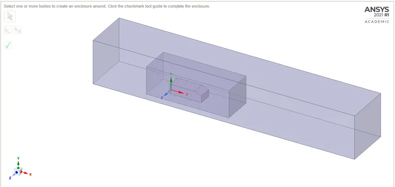
1. A first we have a double encloser around the Ahmed body with a 3d view of the z-axis 2m for the left side 5m for the right side height is 1m and depth is 0m being the first encloser. For the second encloser, 0.5m for the left side 1m for the right side height is 0.5m and depth is 0m.
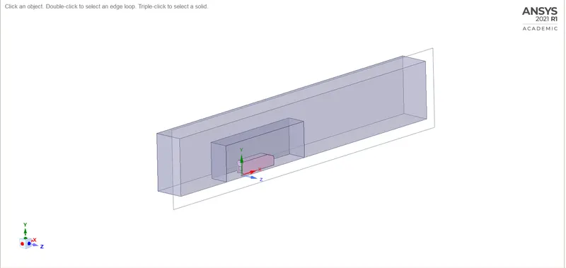
2. Then we cut the body in half to reduce the number of elements of the mesh.
3. Then we check for the interference and share the topology.
4. We suppress the physical properties of the Ahmed body.
GIVEN BODY
AFTER ENCLOSER
AFTER SPLITTING THE BODY
CASE 1: MESH
1. Naming the geometry as to inlet, outlet, car_wall, wall, and symmetry
2. Then using the multi-zone method for the outer encloser
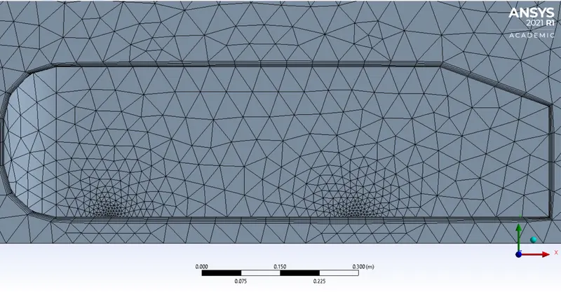
3. For the inner encloser use the body sizing of an element size of 0.05m
4. Face sizing is used for the bottom circles in the car_wall with an element size of 0.025m
5. The total element size of 0.1m and max size 0.1m as well
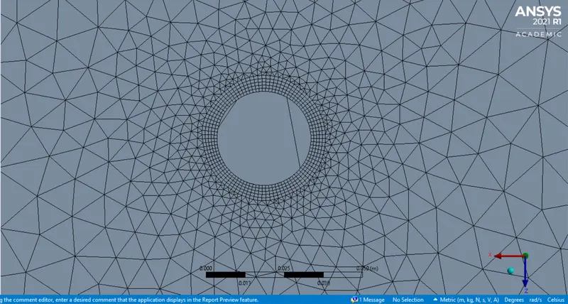
6. Then the inflation for the car_wall using the total thickness with 5 layers and 1.2 growth rate and thickness being 0.012m
which is calculated by the {Number of layers x [growth rate^(number of layers)]}
TOTAL MESH
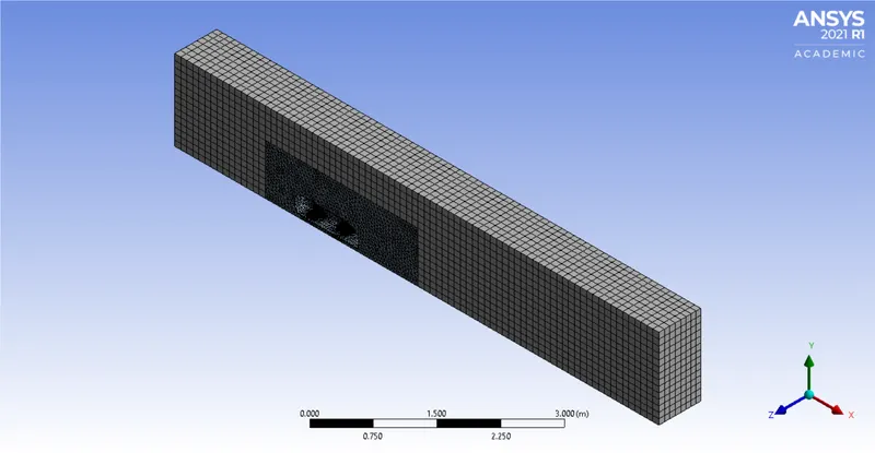
INFLATION LAYER AROUND THE CAR_WALL
Setup and Solution
|
SETUP |
||
|
Solver Type |
Density-Based |
|
|
Velocity Formulation |
Absolute |
|
|
Time |
|
|
|
Viscous Model |
K-epsilon | |
|
Material |
Fluid type: Air |
|
|
Cell zones ff_surface |
Fluid type: Air | |
|
Boundaries |
Inlet (velocity inlet) Velocity Magnitude 25m/s Temperature – standard Outlet x (Pressure outlet) Gauge Pressure – 0 pas. Wall - wall Symmetry - symmetry |
|
|
Reference values |
Area = 0.065741 Density = 1.225 Enthalpy = 0 Pressure = 0 Temperature = 300K Velocity = 25m/s Viscoity = 1.7894e-05 |
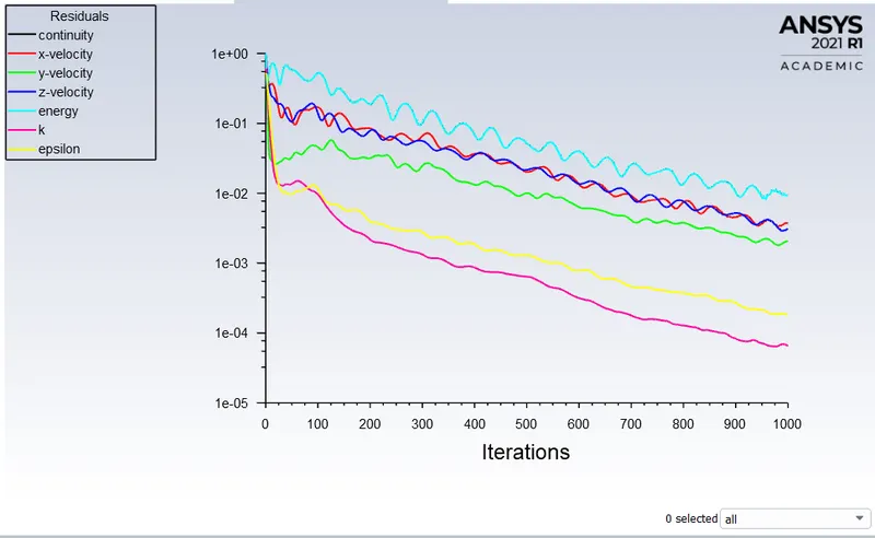
Residual plot
Drag-coefficient plot
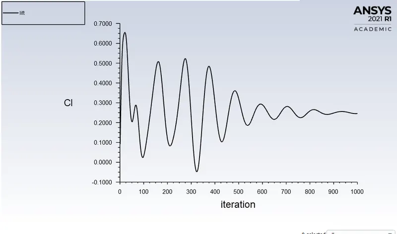
Lift-coefficient plot
Velocity contour
Pressure contour
Velocity Vector
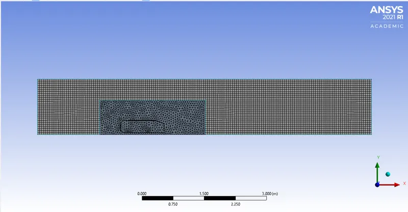
CASE 2: MESH
1. Naming the geometry as to inlet, outlet, car_wall, wall, and symmetry
2. Then using the multi-zone method for the outer encloser
3. For the inner encloser use the body sizing of an element size of 0.05m
4. Face sizing is used for the bottom circles in the car_wall with an element size of 0.01m
5. The total element size of 0.05 m and max size 0.05 m as well
6. Then the inflation for the car_wall using the total thickness with 5 layers and 1.2 growth rate and thickness being 0.012m
which is calculated by the {Number of layers x [growth rate^(number of layers)]}
Repeating the same setup
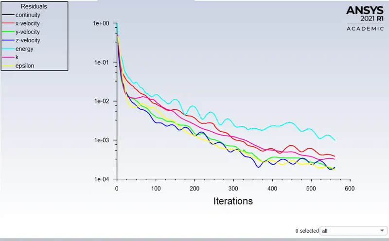
Residual plot
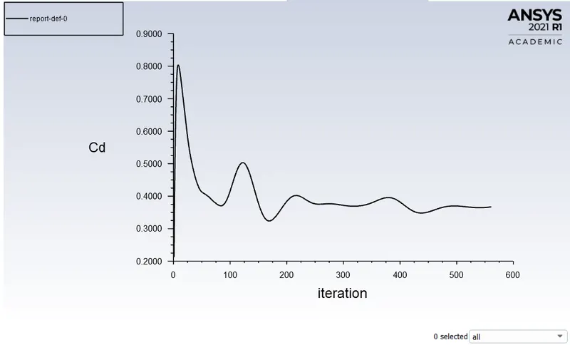
Drag-coefficient plot
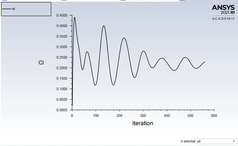
Lift-coefficient plot
Velocity contour
Pressure contour
Velocity Vector
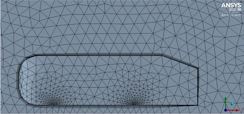
CASE 3: MESH
1. Naming the geometry as to inlet, outlet, car_wall, wall, and symmetry
2. Then using the multi-zone method for the outer encloser
3. For the inner encloser use the body sizing of an element size of 0.06m
4. Face sizing is used for the bottom circles in the car_wall with an element size of 0.01m
5. The total element size of 0.1m and max size 0.096m as well
6. Then the inflation for the car_wall using the total thickness with 6 layers and 1.2 growth rate and thickness being 0.017916 m
which is calculated by the {Number of layers x [growth rate^(number of layers)]}
TOTAL MESH
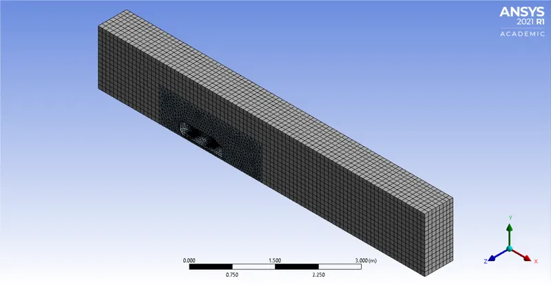
INFLATION LAYERS
Repeating the same setup
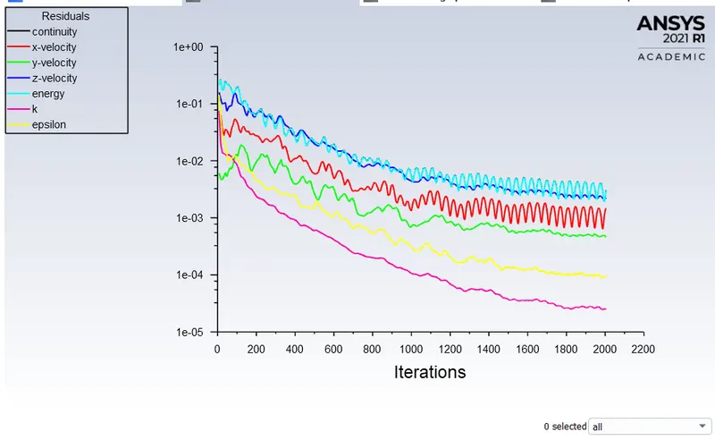
Residual plot
Drag-coefficient plot
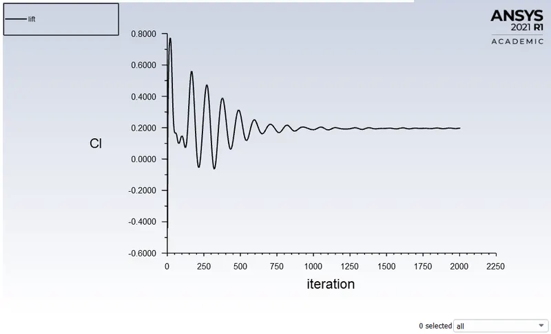
Lift-coefficient plot
Velocity contour
Pressure contour
Velocity Vector
Grid independence test
Comparison of all cases
| Steady-state, Turbulent flow, Density-based, Fluid material-Air | ||||
| Grid Independence Test | Element size in m | No of inflation layers | Lift-Coefficient | Drag-Coefficient |
| Case 1 | 0.1m | 5 | `0.2460` | `0.3467` |
| Case 2 | 0.05 | 5 | `0.2275` | `0.3671` |
| Case 3 | 0.96m | 6 | `0.1965` | `0.3410` |
Conclusion:
- High pressure is formed at the frontal area of the Ahmed body due to the loss of kinetic energy of the air.
- The adverse pressure gradient is created near the wake regions because of the flow separation which is occurring because of the geometry of the model. As a result flow separation alters the pressure gradient which in turn affects the drag and lift coefficients.
- In order to reduce the size of the wake region, detachment of the fluid should be farther away from the body which can be achieved by an increase in the slant angle.
- With the increase in mesh size, the numerical results approach closer to experimental results.