Week 3 - External flow simulation over an Ahmed body.
Objective :
1) Describe Ahmed's body and its importance.
2) Explain the reason for the negative pressure in the wake region.
3) Explain the significance of the point of separation.
4) Plot Velocity and pressure contours.
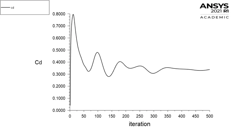
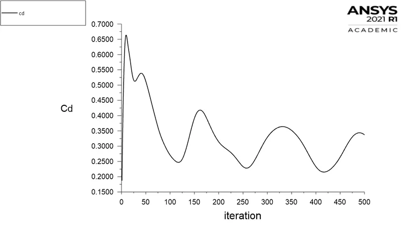
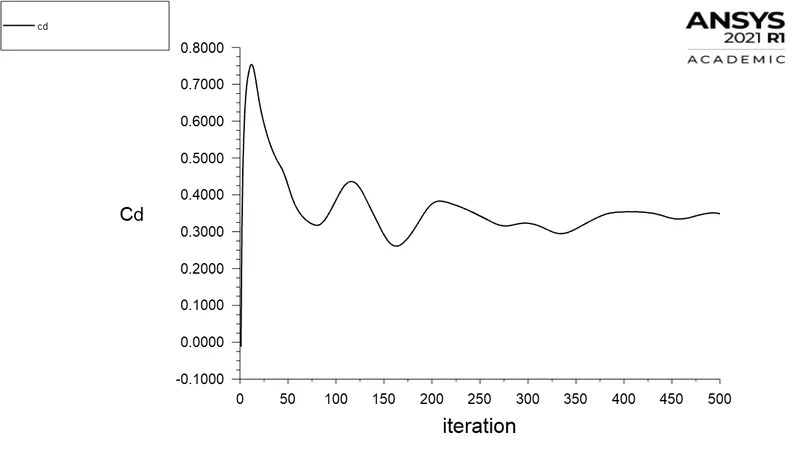
5) The drag coefficient plot for a refined case. ( For velocity of 25m/sec, the drag coefficient should be around 0.33).
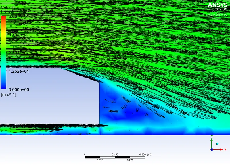
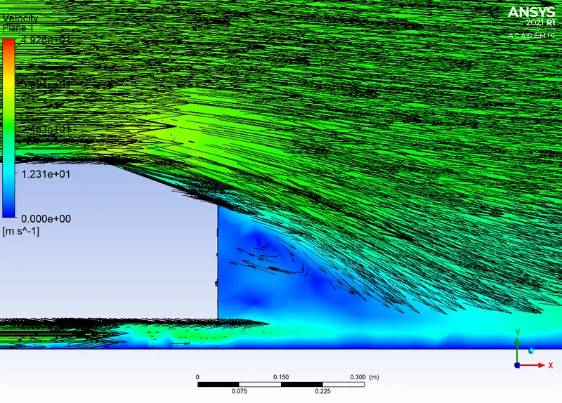
6) The vector plot clearly showing the wake region.
7) Perform the grid independency test and provide the values of drag and lift with each case.
Theory :
The Ahmed body is a geometric shape first proposed by Ahmed and Ramm in 1984. The shape provides a model to study geometric effects on the wakes of ground vehicles (like cars).As the burning of fossil fuels becomes a more pressing issue, manufacturers are introducing more fuel efficient cars to the market. One main contributor to fuel burn is the car’s aerodynamic drag. Complexly shaped, cars are very challenging to model and it’s difficult to quantify the aerodynamic drag computationally. The Ahmed body is a benchmark model widely used in the automotive industry for validating simulation tools. The Ahmed body shape is simple enough to model, while maintaining car-like geometry features.
Case set up:
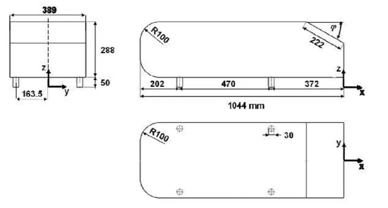
a)Geometry
Dimensions
length in mm
angle in degrees
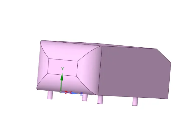
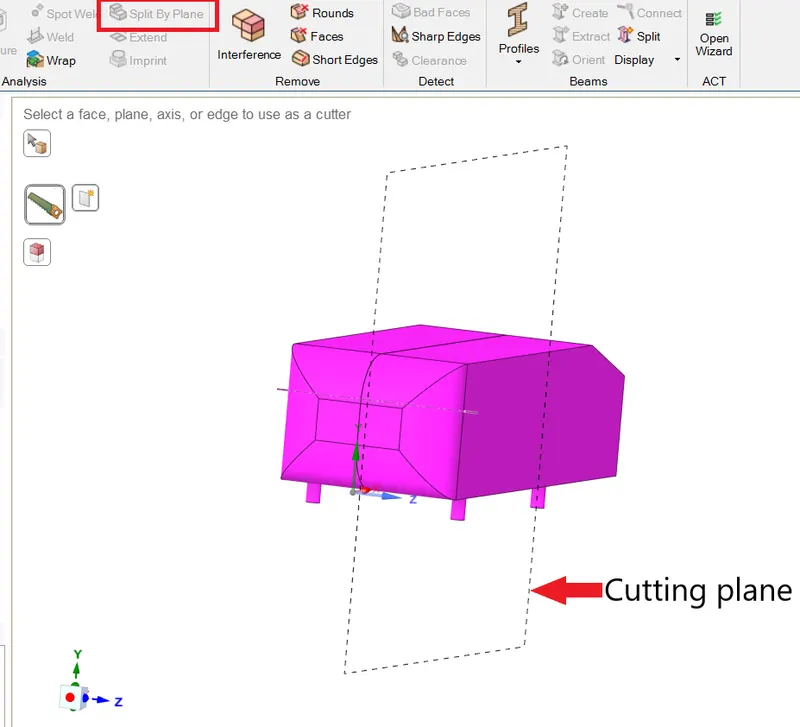
The model was split into half along the xy plane using the split by plane tool .
Initial model
After splitting
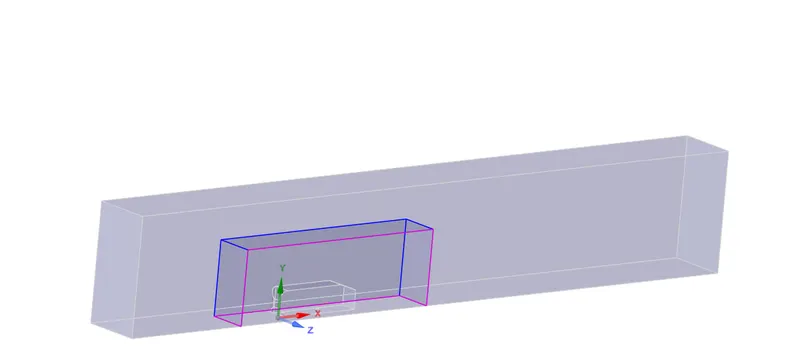
Two enclosures were made to set up the domain and mesh refinement purposes using the enclosure tool .
Dimension for 1st enclosure
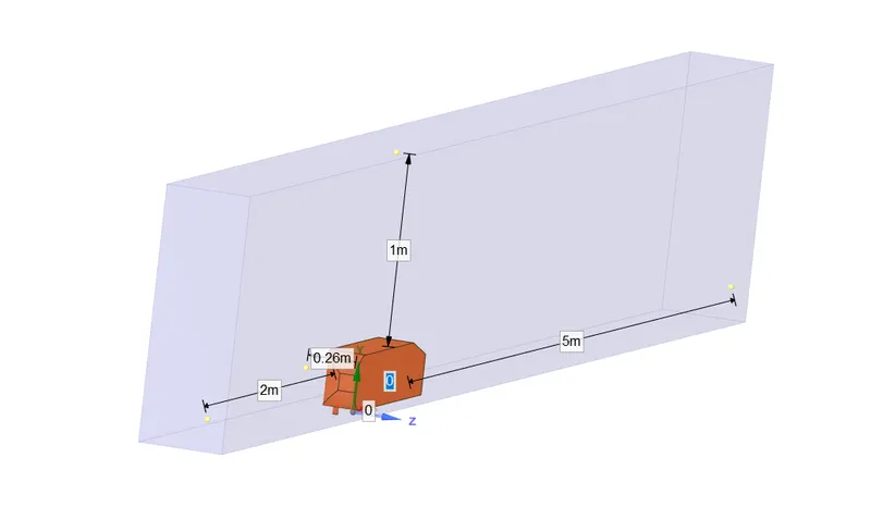
Dimension for 2nd enclosure
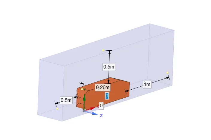
Interference was checked for and topology was set to share . Hence the geometry was prepared for meshing .
b)Meshing
Boundary conditions were given by creating named selections .
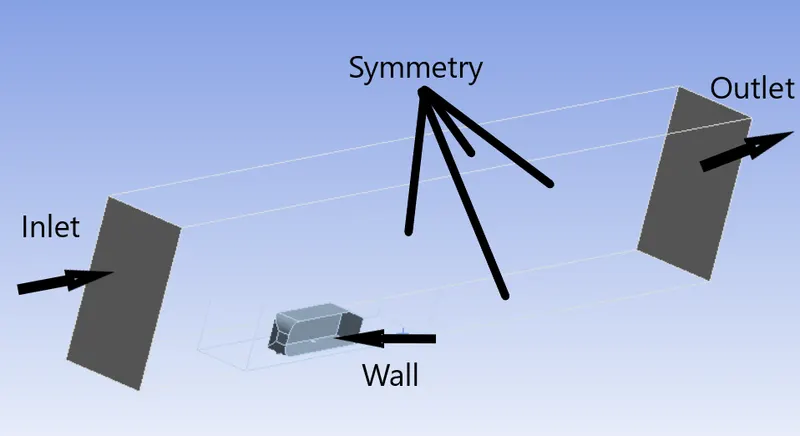
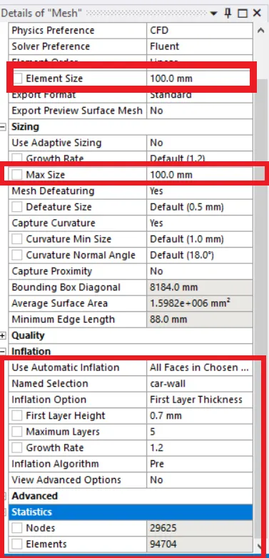
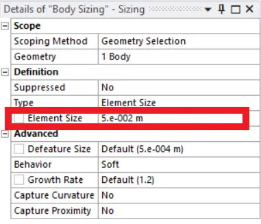
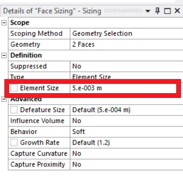
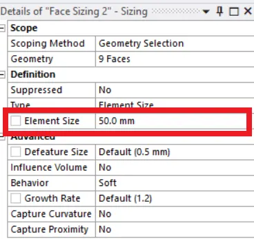
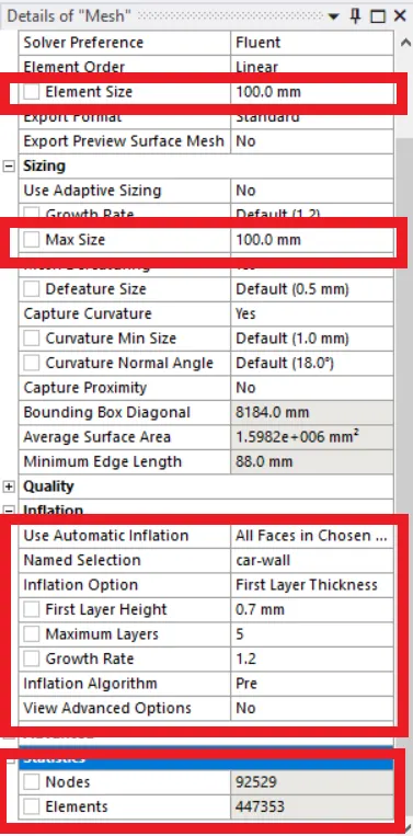
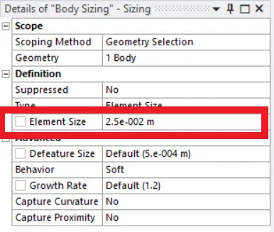
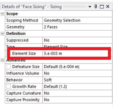
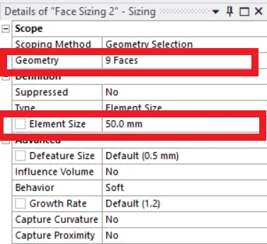
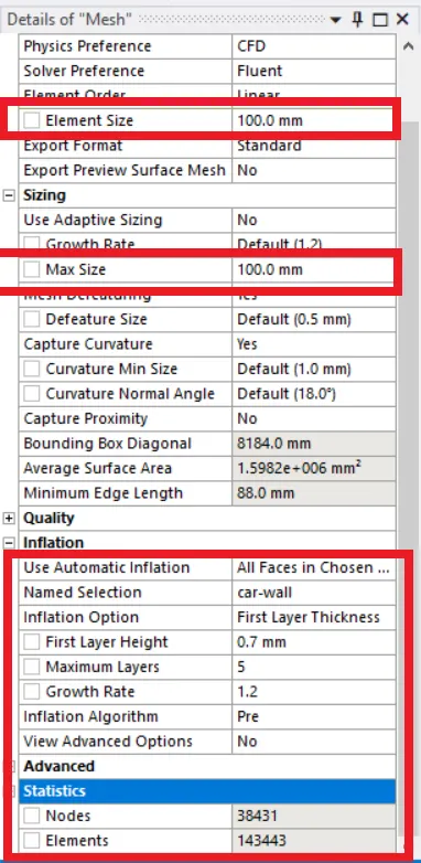
The 1st enclosure was meshed using multizone option in method to create hexa mesh . The 2nd enclosure was meshed using body sizing option after selection of respective geometry to create tetra mesh . To capture the physics near car-wall better, face sizing was also used to increase the cell count and allign the cell center . To further improve the results, inflation was also used near the car wall to create hexa mesh along the boundary of the surface .
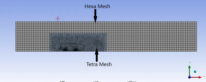
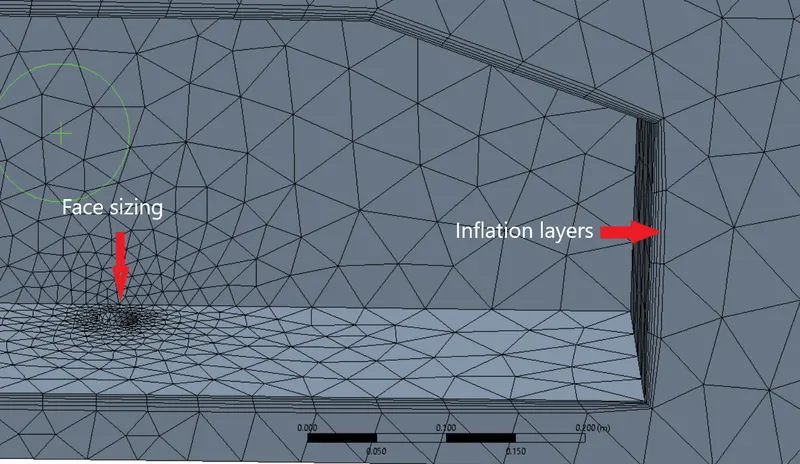
Hence Meshing was completed and set up module was opened .
c)Set up
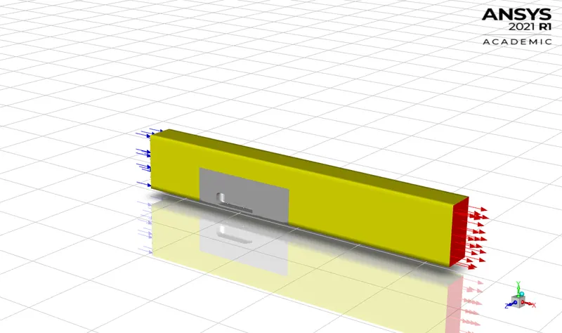
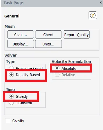
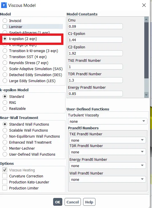
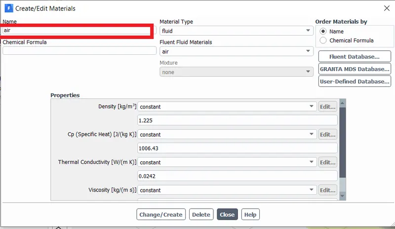
Once the meshed model was opened in set up module , the solve type was set to density based absolute type in steady state time . The k-epsilon viscous model was chosen . Working material was selected as air . Boundary condition values were entered and inlet velocity was se to 25m/s .
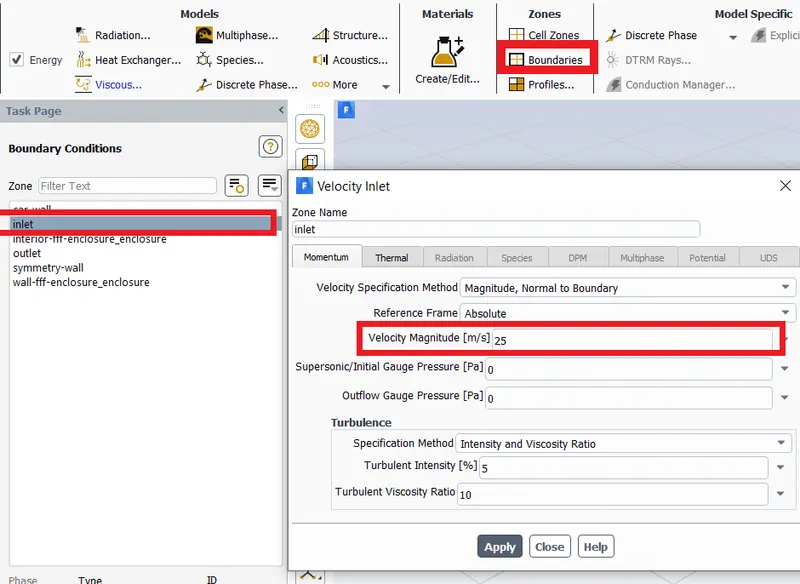
Requests were made for Co-efficient of drag and lift after initialization was done . The solution was made to run for 500 iterations .
d)Results
case 1:
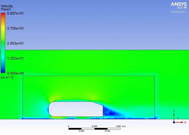
Velocity Contour
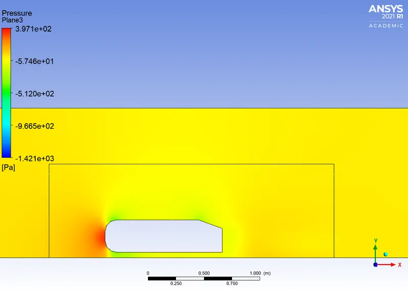
Pressure contour
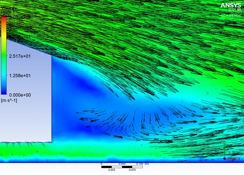
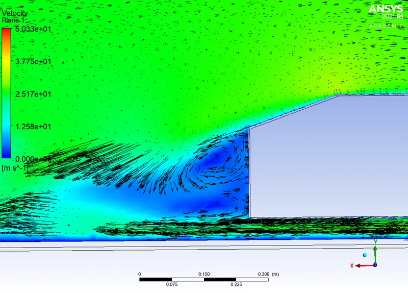
Vector plot for velocity
Drag-coefficient plot
CASE 2:
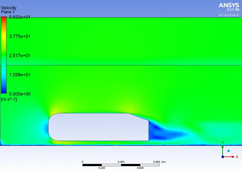
Velocity Contour
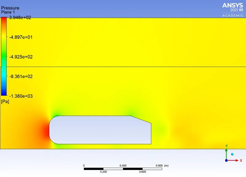
Pressure Contour
Vector plot for velocity
Co-efficient of Drag
CASE 3:
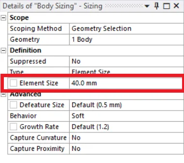
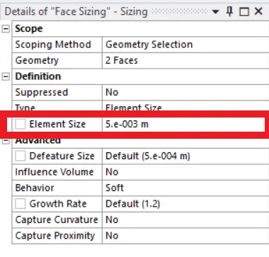
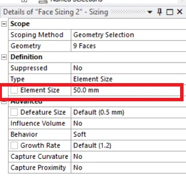
Velocity Contour
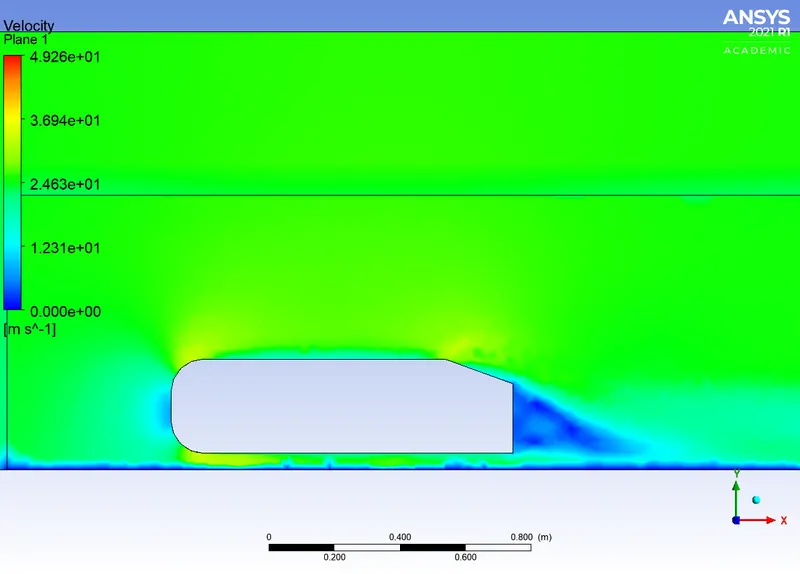
Pressure Contour

Vector plot for velocity
Co-efficient of Drag
Grid independence test
| Sl No |
Element size (Body Mesh) in m |
Total Elements | Co-effient of lift | Co-efficent of Drag Numerical | Co-efficient of Drag Reference Value |
| CASE 1 | .05 | 94704 | .225 | .338 | .33 |
| CASE 2 | .025 | 447353 | .402 | .340 | .33 |
| CASE 3 | 0.4 | 143443 | .182 | .348 | .33 |
The numerical values obtained for Cd has <5% error . Hence grid independence is obtained.
Inference:
1) The flow over Ahmed body generates 2 recirculation areas in the rear area
a) One due to flow seperation from top side
b) one due to flow seperation from bottom side
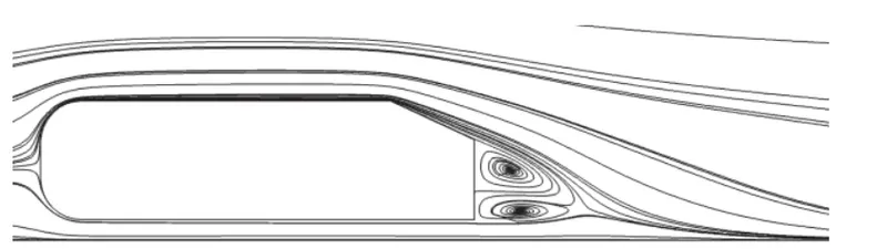
2) From the pressure contours , we can see that the maximum pressure is formed at the front of the Ahmed body , this is due to the loss in kinetic energy brought about by rapid change in direction of the fluid . An adverse pressure gradient is created near the wake region due to flow seperation .This causes formation of vortices ,which creates a vaccum like effect. This difference in pressure is reason for Drag .
3) Drag can be reduced by reducing the size of the wake region by increasing the slant angle , or using aerofoils . The main idea behind this is to delay the point of flow seperation .