Week 3 - External flow simulation over an Ahmed body.
Aim: - To simulate external flow over an Ahmed Body.
Objective: -
- Discussing Ahmed body and its significance.
- To run the Steady State simulation for the velocity of 25 m/sec with the default air properties in fluent using fine and courser mesh respectively.
Theory: -
Ahmed body: Ahmed body represents the simplified ground vehicle geometry of a bluff body type. Its shape is simple enough for accurate flow simulation and retains some important characteristic features relevant to automobiles body. S.R. AHMED developed this specimen in 1984.
This model is also used to describe the turbulent flow field around a car-like geometry, below is the general design of the structure.
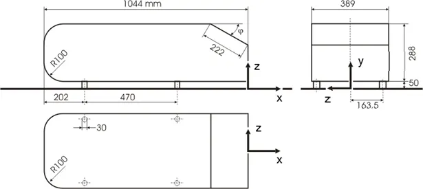
The aim of flow test over Ahmed body is to determine Coefficient of drag and velocity profiles of the flow. It is also suitable to study Wake region (due to flow separation at rear end) characteristic.
Flow separation:
It has been observed that the flow is reversed at the vicinity of the wall under certain conditions. This phenomenon is called flow separation. Separation takes place due to excessive momentum loss near the wall in a boundary layer trying to move downstream against increasing pressure, i.e., , which is called adverse pressure gradient.
Depending upon the magnitude of adverse pressure gradient, the fluid particles, in the boundary layer are separated from the wall and driven in the upstream direction. However, the far field external stream pushes back these separated layers together with it and develops a broad pulsating wake behind the cylinder. Since boundary layer is destroyed beyond this point, flow continues along the free stream and region behind this point, remains stagnant. This point is called Point of flow separation.
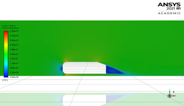
Free stream flow over this region, will twist this region creating a vortex which dissipates energy and pressure will drop in this region. This pressure difference will introduce what is known as form drag which along with skin drag, contribute to the opposing forces for motion of object, thereby increasing demand for energy to sustain the motion.
Calculation of Y+
First layer thickness is calculated for Y+ = 100.
Following parameters and their values are used in calculation and case setup
Density = 1.225 kg/`m^3` Viscosity = 1.789 * 10^-5 kg/m-s Velocity at inlet =25 m/s
Re`= (ρ*v*l)/µ` ==> Re = 1786772.1
`C_f=0.0576/(Re)^(1/5)` ==> `C_f`= .003236
`τ_w =(C_f×ρ×v^2)/2` ==> `τ_w`=1.23878 N/m2
`u_f= √(τ_w/ρ)` ==> `u_f`= 1.00561 m/s
As Y+ value considered for all the simulation is 100, hence first layer thickness
`y=(μ*Y+)/(ρ*u_f )` ==> y = .00145 m
Here All the simulation is done with first inflation layer thick ness less than .001 m.
Pre-Processing: -
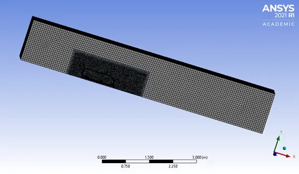
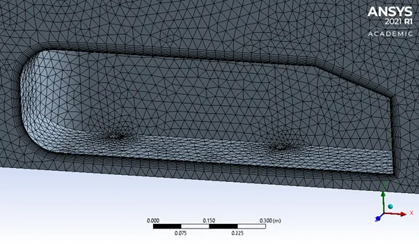
Geometry – It includes two enclosers around Ahmed body, one big and one small and then the whole geometry is split using split Body tab.
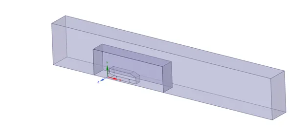
Meshing: - It is done in two ways finer and coarser.
Coarser Mesh –
Number of Elements: 1,04,998 Outer encloser Mesh size: 0.1m Inner Encloser Mesh size: 50 mm Inflation Layer: Based on total thickness i.e., 50 mm for 13 layers.
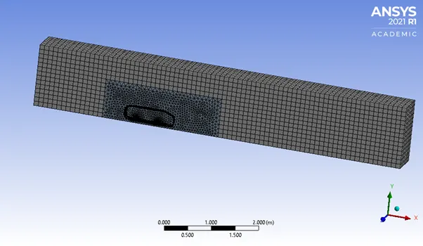
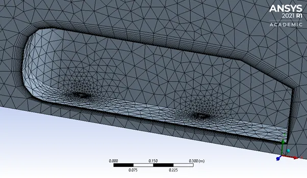
Finer Mesh –
Number of Elements: 5,11,906 Outer encloser Mesh size: 60 mm Inner Encloser Mesh size: 25 mm Inflation Layer: Based on First layer thickness i.e., 1 mm for 10 layers.
Models Used: Two models are used for each type of meshing.
- K-epsilon model with Non-Equilibrium Wall Function
- K-Omega SST Model
Solution Method and Reference Values:
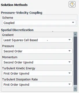
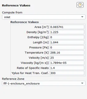
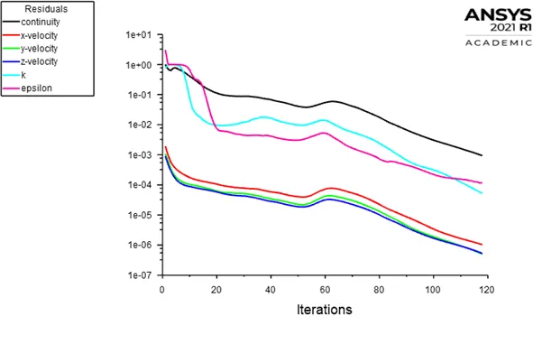
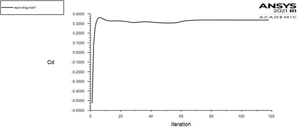
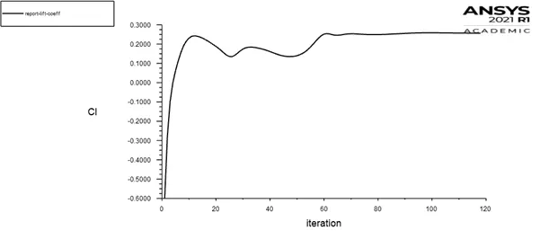
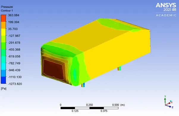
- K-epsilon with Non-Equilibrium wall function (Coarser)
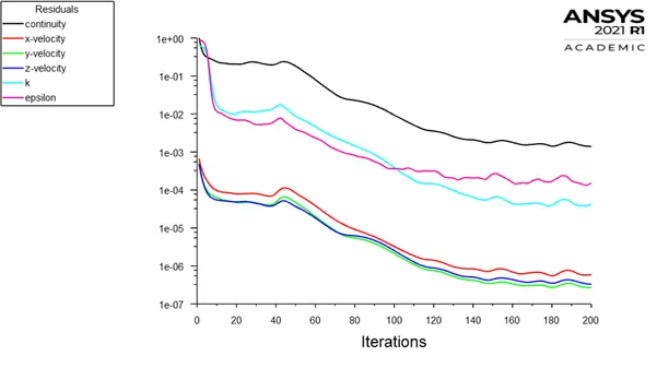
Residual Plot:
Coefficient of Drag:
Coefficient of Lift:
Pressure Contour on Car wall:
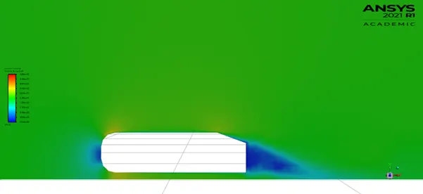
Velocity Contour:
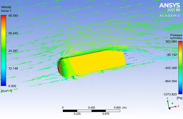
Vector Plot of Velocity:
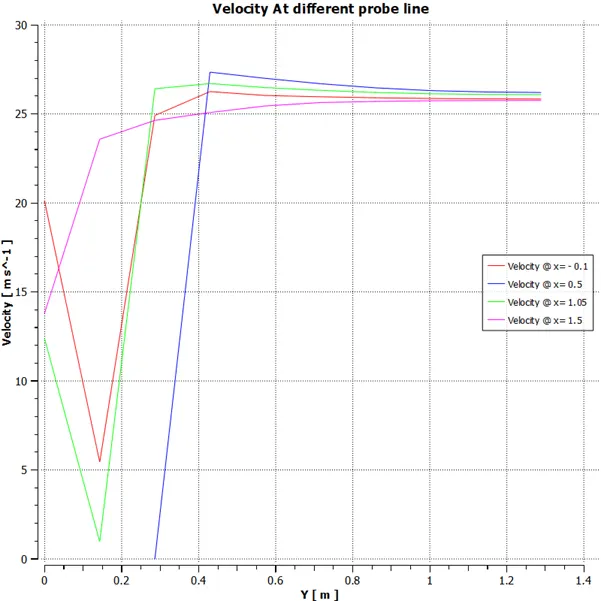
Velocity Profile along Different Line from Front of AHMED BODY
- K-epsilon with Non-Equilibrium wall function (finer)
Residual Plot:
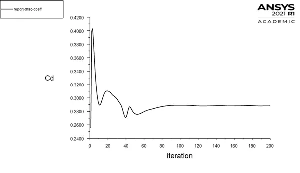
Coefficient of Drag:
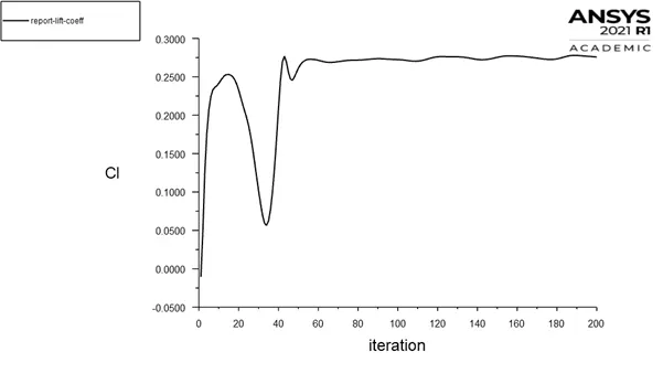
Coefficient of Lift:
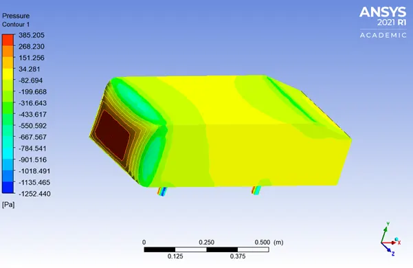
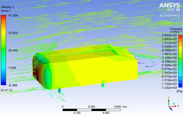
Pressure Contour on Car wall:
Velocity Contour:
Vector Plot of Velocity:
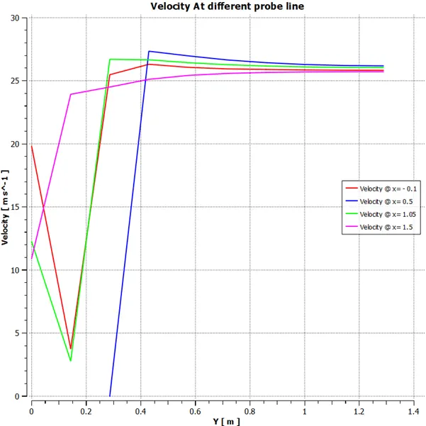
Velocity Profile along Different Line from Front of AHMED BODY
- K-Omega SST (Coarser)
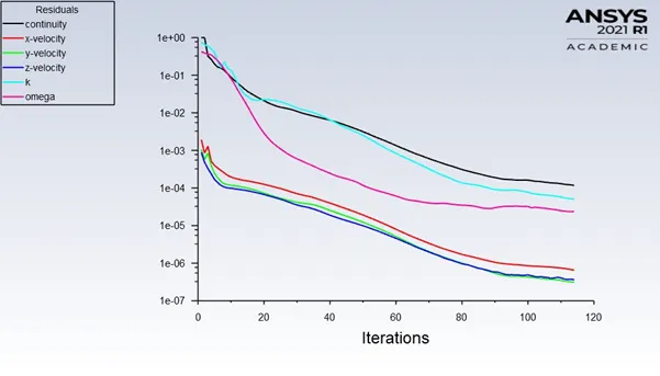
Residual Plot:
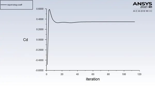
Coefficient of Drag:
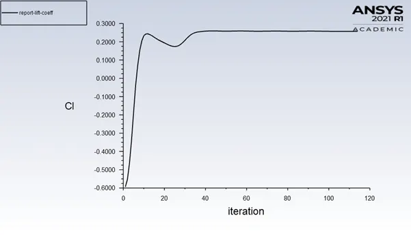
Coefficient of Lift:
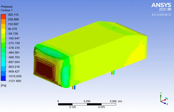
Pressure Contour on Car wall:
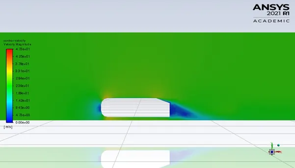
Velocity Contour:
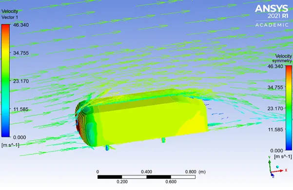
Vector Plot of Velocity:
Velocity Profile along Different Line from Front of AHMED BODY
- K-Omega SST (Finer)
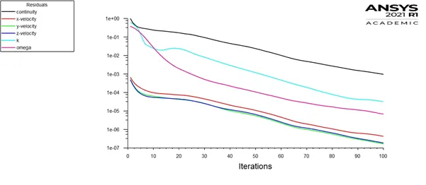
Residual Plot:
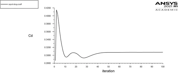
Coefficient of Drag:
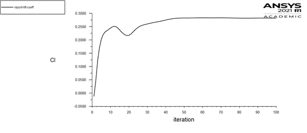
Coefficient of Lift:
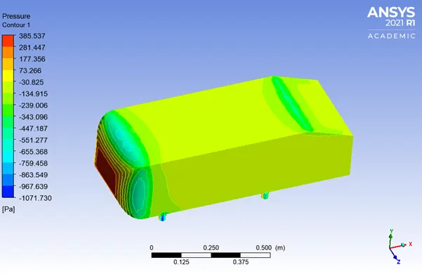
Pressure Contour on Car wall:
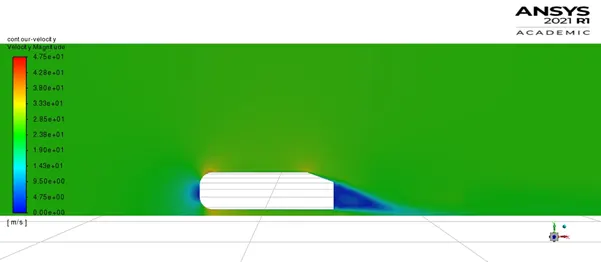
Velocity Contour:
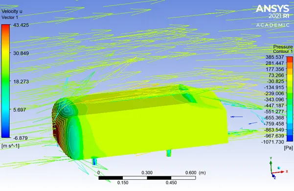
Vector Plot of Velocity:
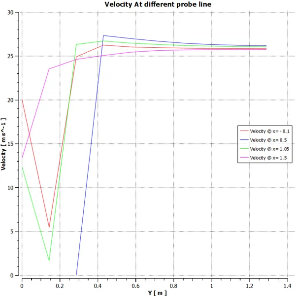
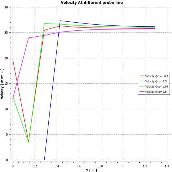
Velocity Profile along Different Line from Front of AHMED BODY
Grid Test:
|
Model (Meshing) |
Number of Element |
Drag Coefficient |
Lift Coefficient |
|
K- with Non-Equilibrium wall function (Coarser) |
1,04,998 |
0.3351983 |
0.2567464 |
|
K- with Non-Equilibrium wall function (finer) |
5,11,906 |
0.2882648 |
0.2757211 |
|
K- SST (Coarser) |
1,04,998 |
0.3471739 |
0.2571552 |
|
K- SST (Finer) |
5,11,906 |
0.3076645 |
0.2818215 |
Conclusion: -
- The Analytical value of drag coefficient for inlet velocity of 25 m/s is 0.33 where the maximum error is 12.7%.
- To counter recirculation due to flow separation and shear stress effect produced pressure turns negative in the wake region.