Week 3 - External flow simulation over an Ahmed body.
OBJECTIVE
To perform a External flow simulation over a Ahmed body
CONDITIONS STATED
To perform the simulation with a inlet fluid velocity of 25m/s with default air properties in fluent.
AHMED BODY
Ahmed body is a reffered Benchmark automotive model used for capturing the flow over the model experimenting it with the data terms and comparing it with any automotive like geometries to interpret high quality turbulence, wake , prssure difference, and velocity results.
In this Simulation , the Ahmed body is set for a study in a enclosed medium approaching a inlet velocity of 25m/s.
Ahmed Body
SIGNIFICANCE OF PRESSURE.
The Drag experienced in a object whenever it approaches a flow has two types
- Pressure drag
- Friction drag
Pressure drag
Pressure drag is caused due to the pressure difference between front end and rear end of the object experiencing the flow.
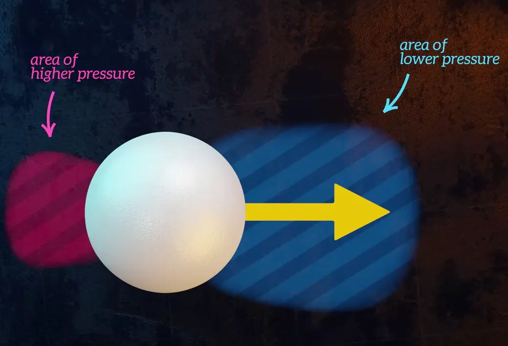
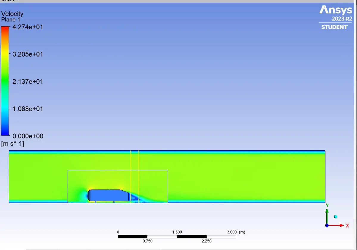
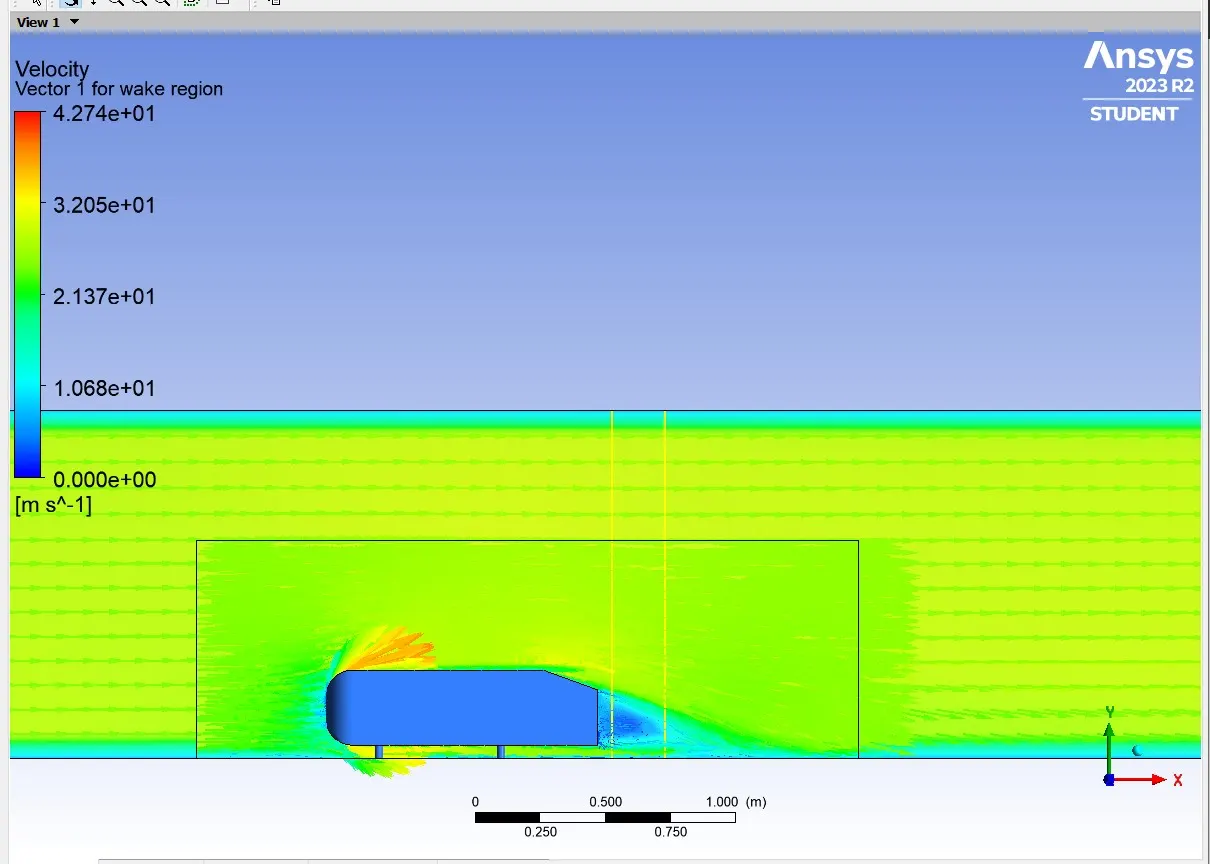
Usually pressure drag is significantly for blunt bodies. Pressure drag is increased if flow separation occurs in prior , i.e Flow separation occurs whenever the fuid detaches from the boundary layer creating a Low pressure area called wake region. This in turn if increased, the flow moving causes negative pressure on the wake region.
POINT OF SEPARATION
Point of separation depends on the geometry of the material , Here in Ahmed body the point of separation is where the fluid flow detaches from the boundary layer of the flow on the car wall edge
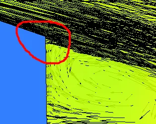
This point of separation is significant with the geometry of the object as the point of sepatration, and the velocity of the flow determines the wake region. If the rear angle of the geometry `psi`is large fluid detachment from the boundary layer would be very obvious and the wake emerging on the rear allocates for large negative pressure values.
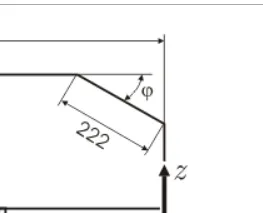
Same If the angle is less, the fluid tends to move along the car wall to create less drag force on the object.
BASELINE SETUP AND SOLUTION
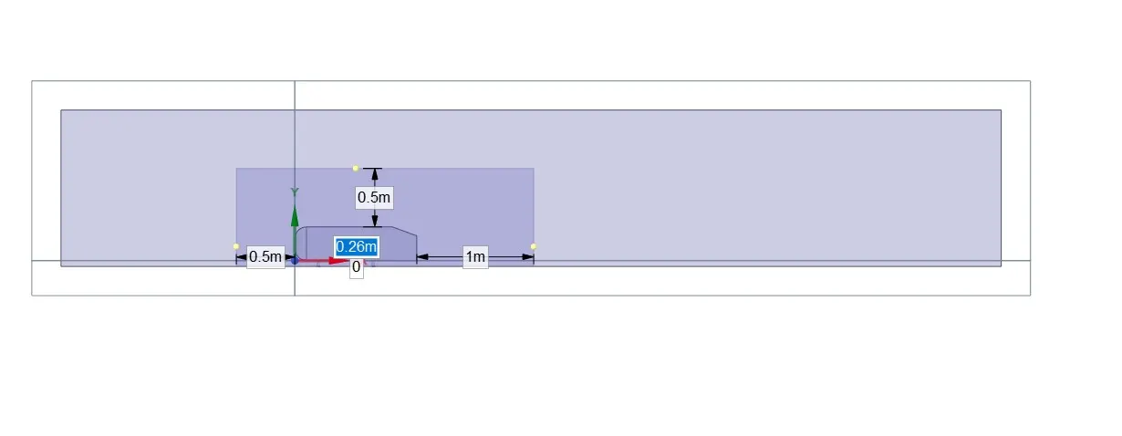
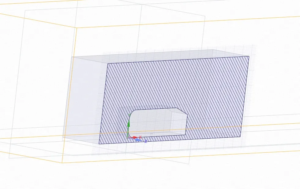
GEOMETRY
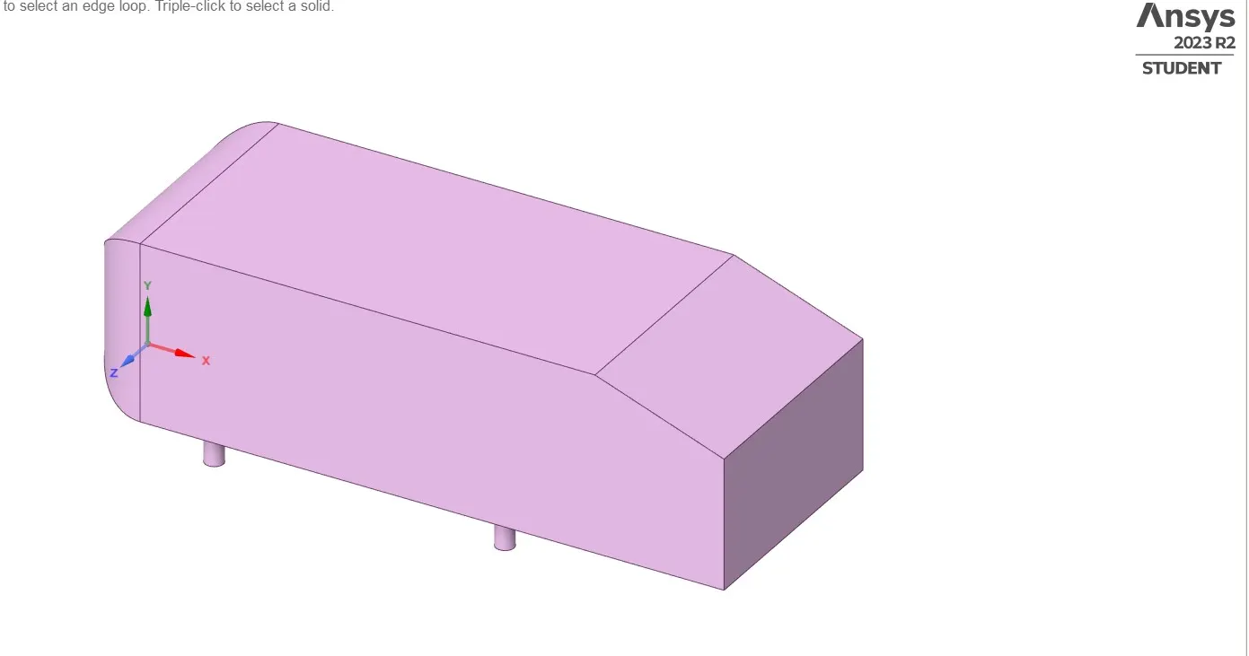
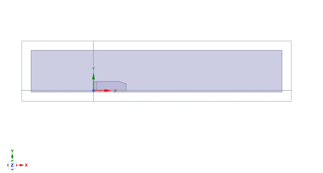
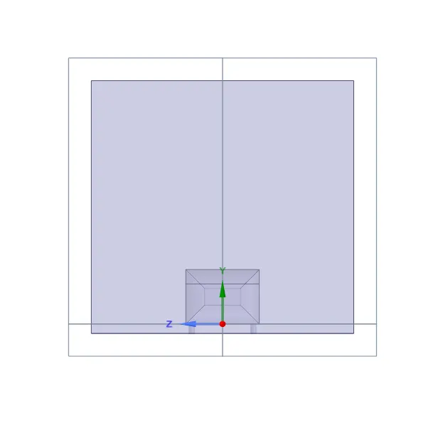
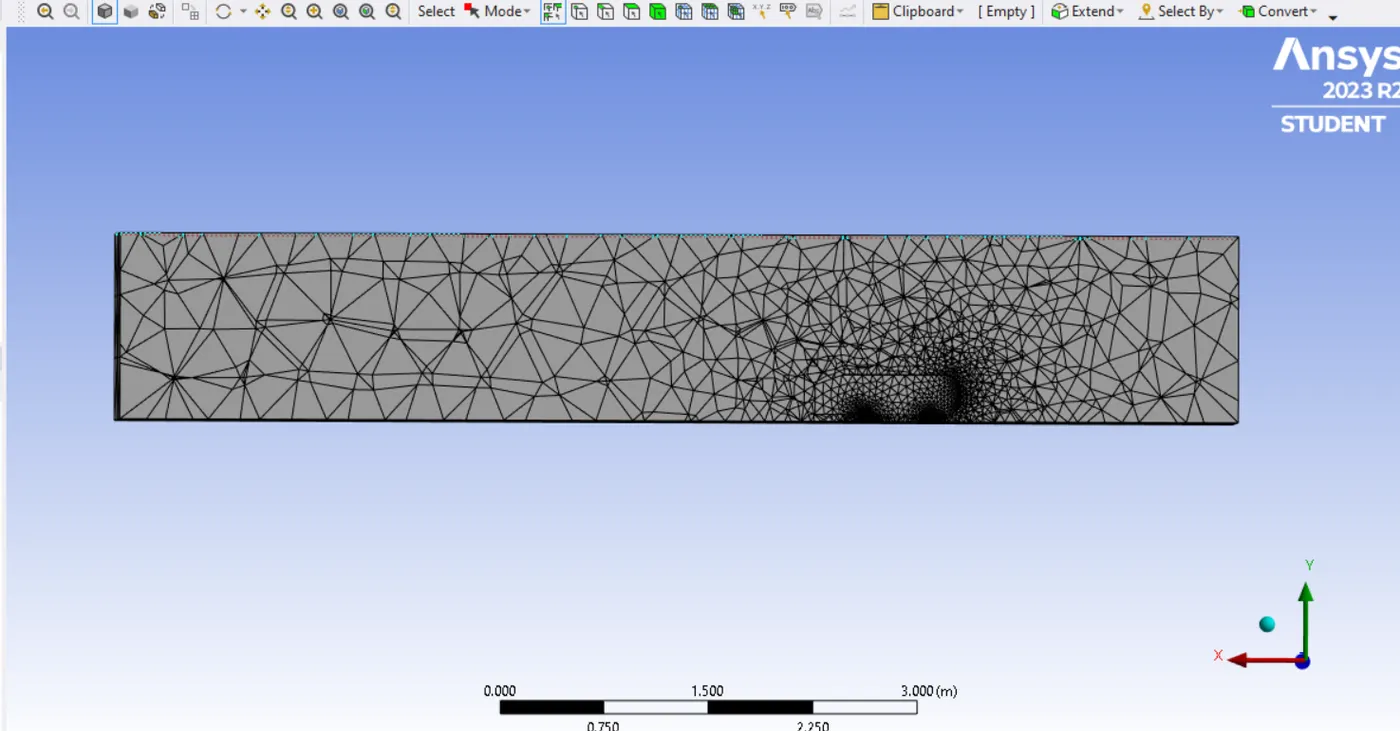
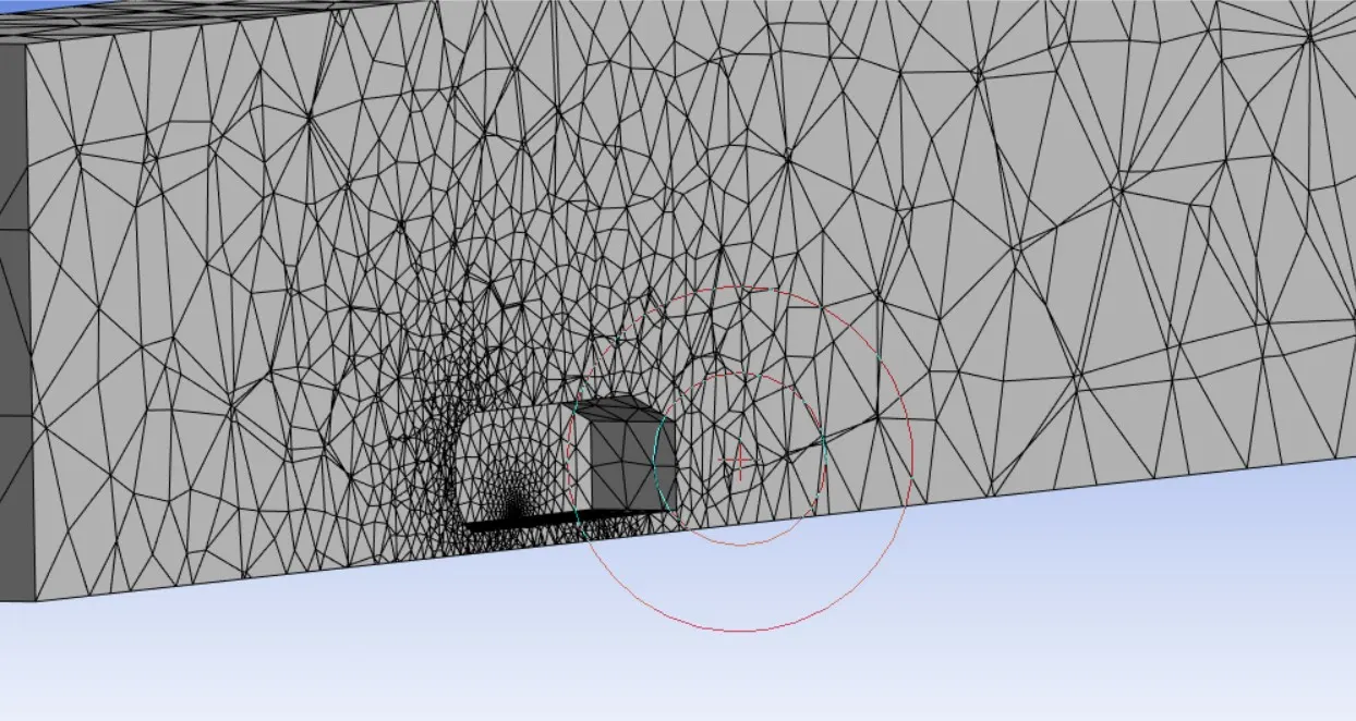
Mesh setup
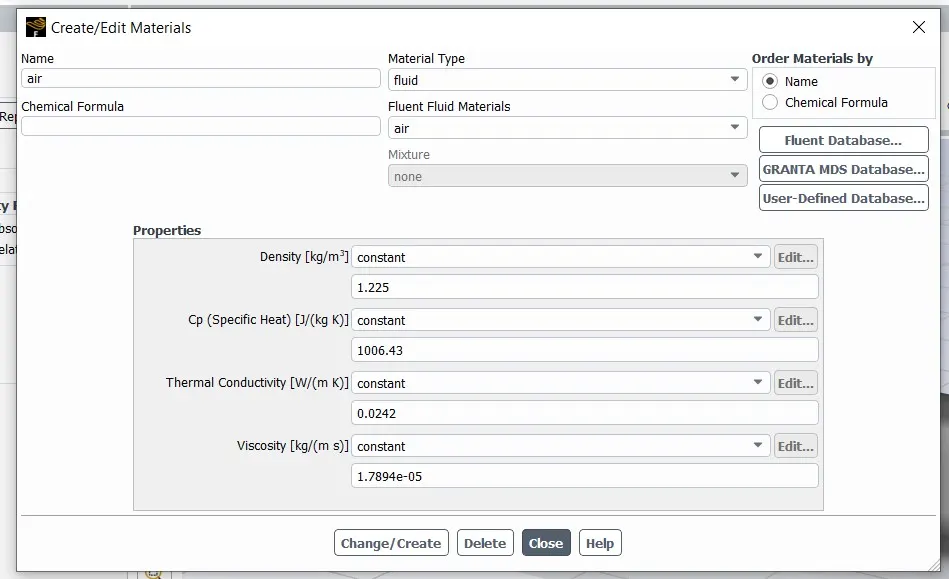
Setup
Results
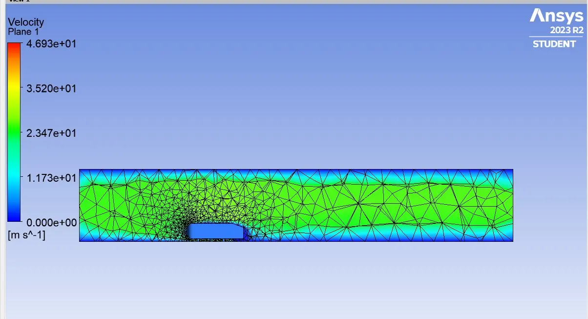
Ahmed body simulation when solved with a enclosure around the car wall , inflation layers around the car wall and with a refined mesh study.
Ahmed body simulation with double enclosure
Geometry
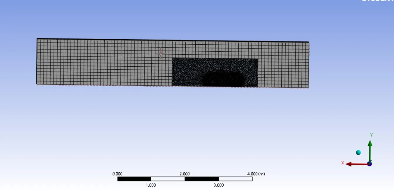
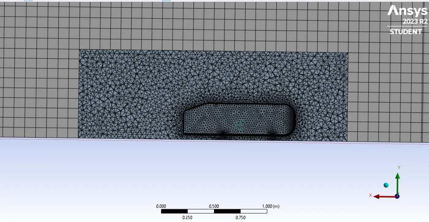
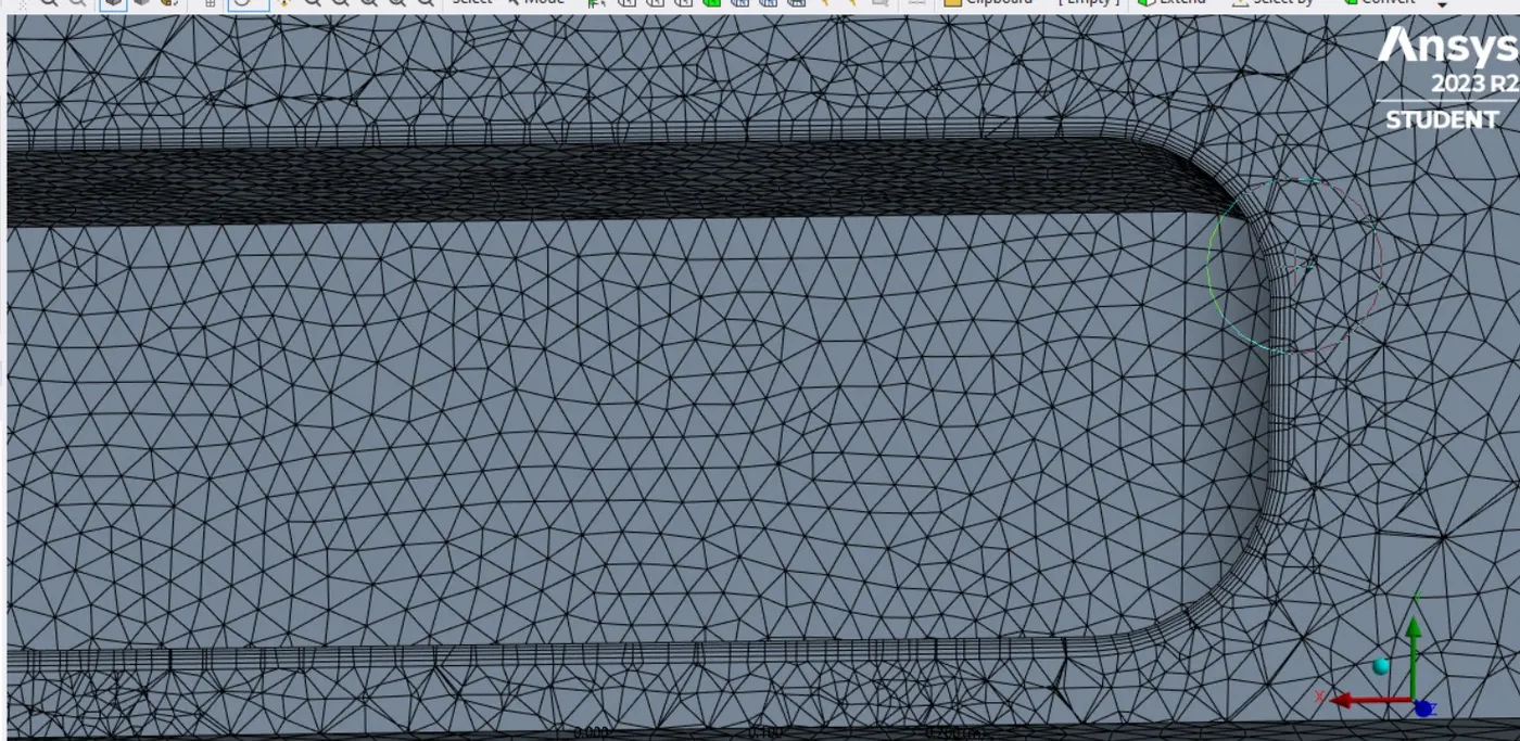
Mesh
1st Enclosure = 0.83m
2nd Enclosure = 0.05m
Car wall = 0.02m
Inflation layer total thickness = 0.01124m
Setup
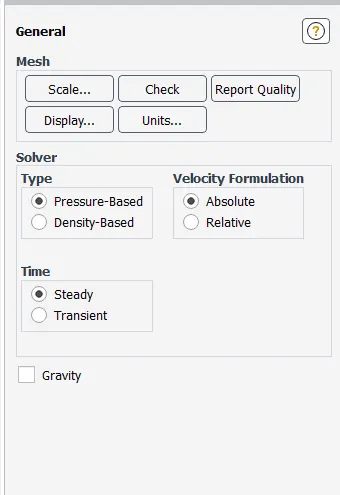
velocity = 25m/s
Density = 1.225 kg/m^3
Turbulence - K epsilon method
Results
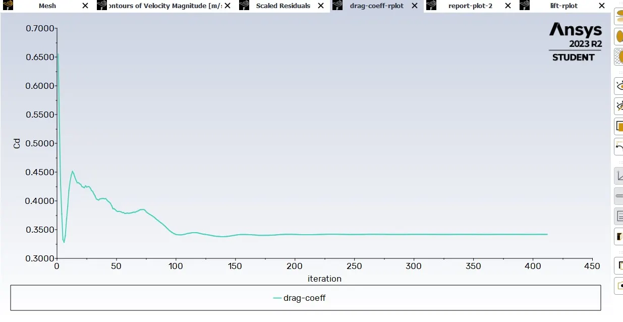
Drag Coefficient
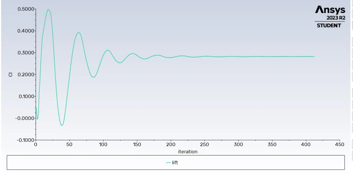
Lift Coefficient
Velocity Contour plot
Pressure plot
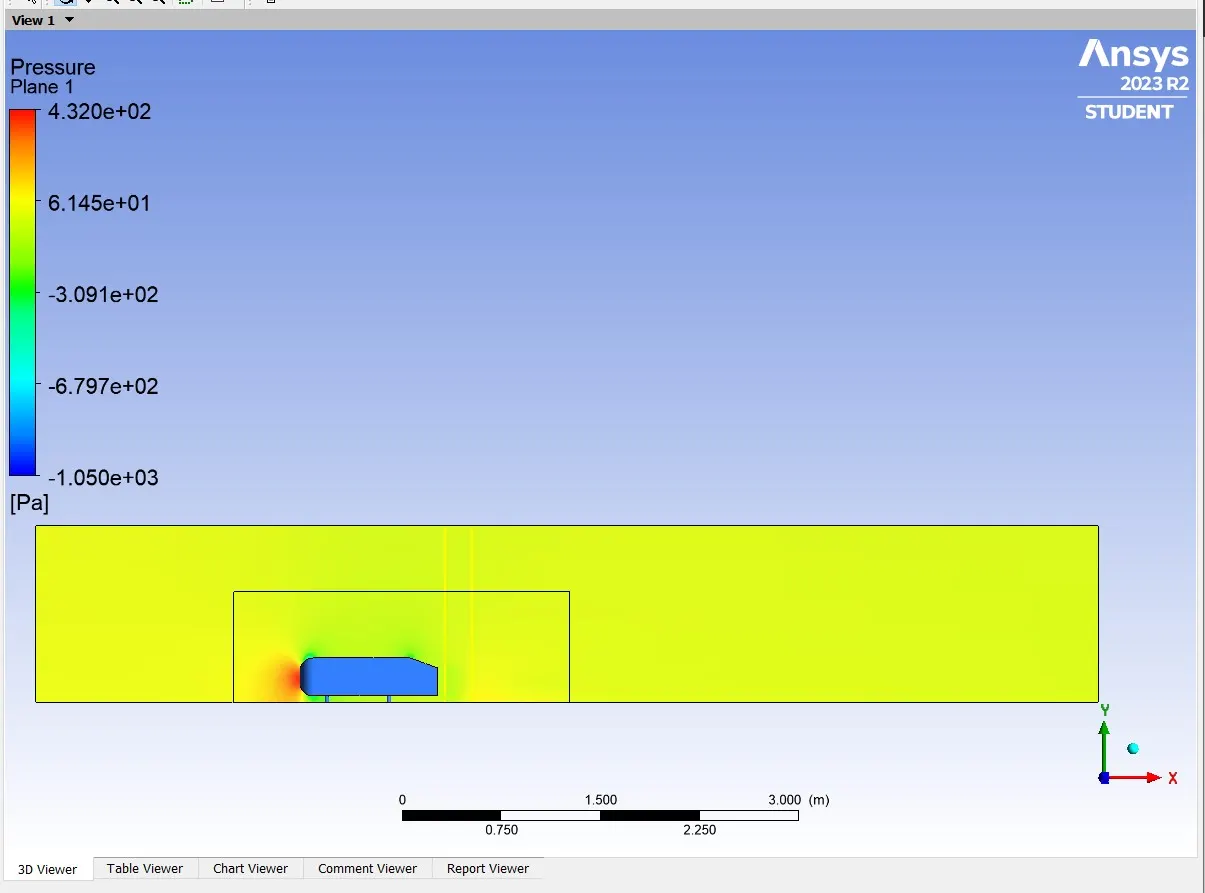
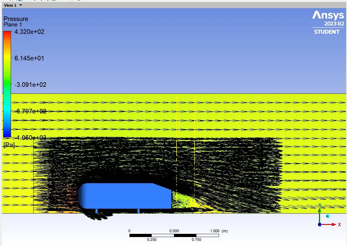
Scaled Residuals
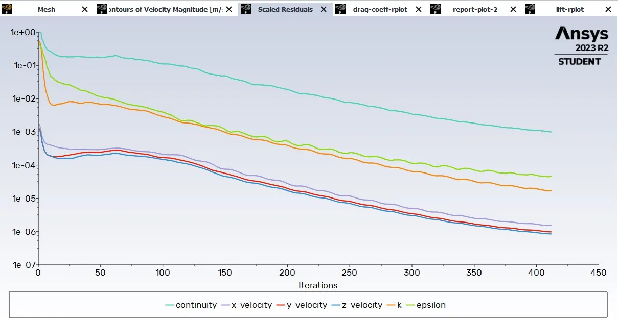
TEST RESULTS
- Three cases are simulated with variation in the grid sizes
Case 1 - Coarse mesh simulation without enclosure
Case 2 - 1st Enclosure box - 0.1m
2nd Enclosure box - 0.07m
Case 3 - 1st Enclosure box - 0.1m
2nd Enclosure box 0.04m
Grid Independent Test
|
CASES |
MESH ELEMENTS |
DRAG COEFF(Cd) |
LIFT COEFF(Cl) |
|
Case 1 |
84073 |
0.39461 |
0.2884 |
|
Case2 |
1,32607 |
0.4019 |
0.3299 |
|
Case3 |
3,23594 |
0.3642 |
0.2873 |
- As the Mesh is refined and specific thickness for Inflation layers are given the Cd,Cl values are converged to 0.33 and 0.28 respectively.