Week 3 - External flow simulation over an Ahmed body.
Aim- CFD analysis of Ahmed body.
Introduction-
Importance of Ahmed Body-
- S.R. Ahmed invented the first simpler automobile body, known as the Ahmed body.This form offers a model for investigating the impact of geometry on the wakes left by ground vehicles. This kind of standard geometry applies to car bodies.
- The turbulent flow field that surrounds a shape like an automobile is also described using this model. The numerical model is used to create new automobile models after it has been verified.
- Being simple in geometry is one of the many advantages of Amed body that nearly captures the flow of air around an actual car as one gets an idea about what drag, lift coefficient should to be designed car should have just by analysig this model.
Reason foe the nagative pressure in the wake region
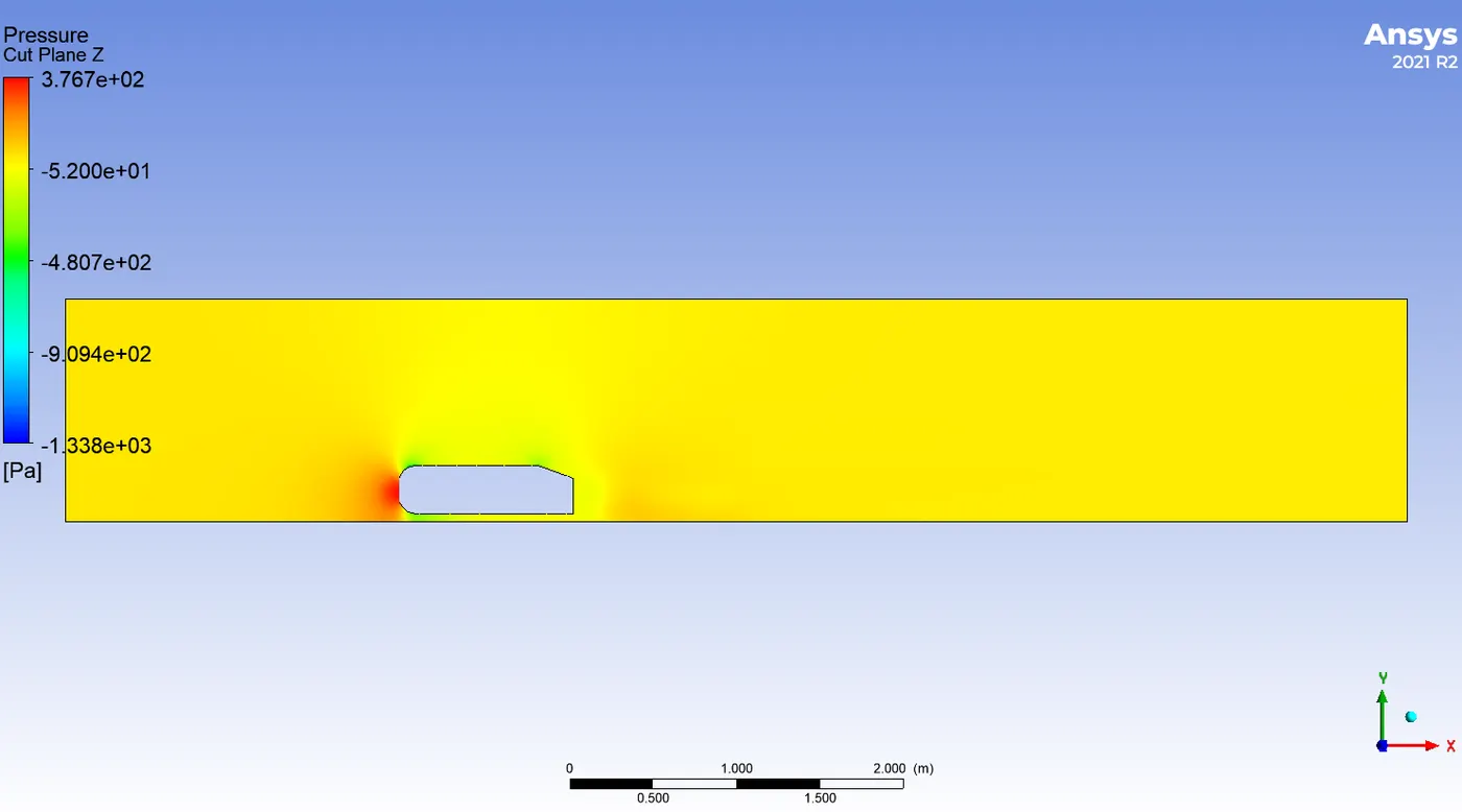
- The wake is the highly turbulent area that forms when the flow behind an item separates from the surface. As the flow splits and a net pressure force (pressure drag) is generated, the pressure inside the wake zone stays low. In other words, the pressure in the wake zone is low because of the pressure drag caused by flow separation. The vacuum gets generated by this.
Significance of point of seperation
- The separation point is where an item travelling through the air ceases "sticking" to the air. The air molecules push back on an item as it moves through the air and impede its motion; this resistance is known as pressure drag. The boundary layer is created when the air "sticks" to an item as it moves around it. This "attached flow" is proceeding with great fluidity. The separation point is the location on the body where the boundary layer rises above the surface. The pressure drag often rises as the air flow splits from the surface.
Solver & Modelling Approach-
- To model I downloded the .stp file from website.
- We dragged that model to spaceclaim.
- Created closure from prepare option.
- Created another closure for refined case.
- Removed interferance between two enclosures.
- Suppressed Ahmed body for physics.
Pre-Processor and Solving Approach-
- After that I closed the Spaceclaim.
- Then I moved to Mesh tab.
- In Mesh tab I first created named selection.
- For the first case I created baseline mesh.
- For second case i.e. Refined Case I and Refined Case II, I created refined mesh including second closure.
- I included Multizone Meshing method, includied body sizing for the inner closure and face sizing for bottom wheels.
- I also included inflation to help me capture flow near boundary of Ahmed body.
Results-
Note:
Baseline Contour- Mesh Size- 413mm, No inflation, No Method, No body and face sizing
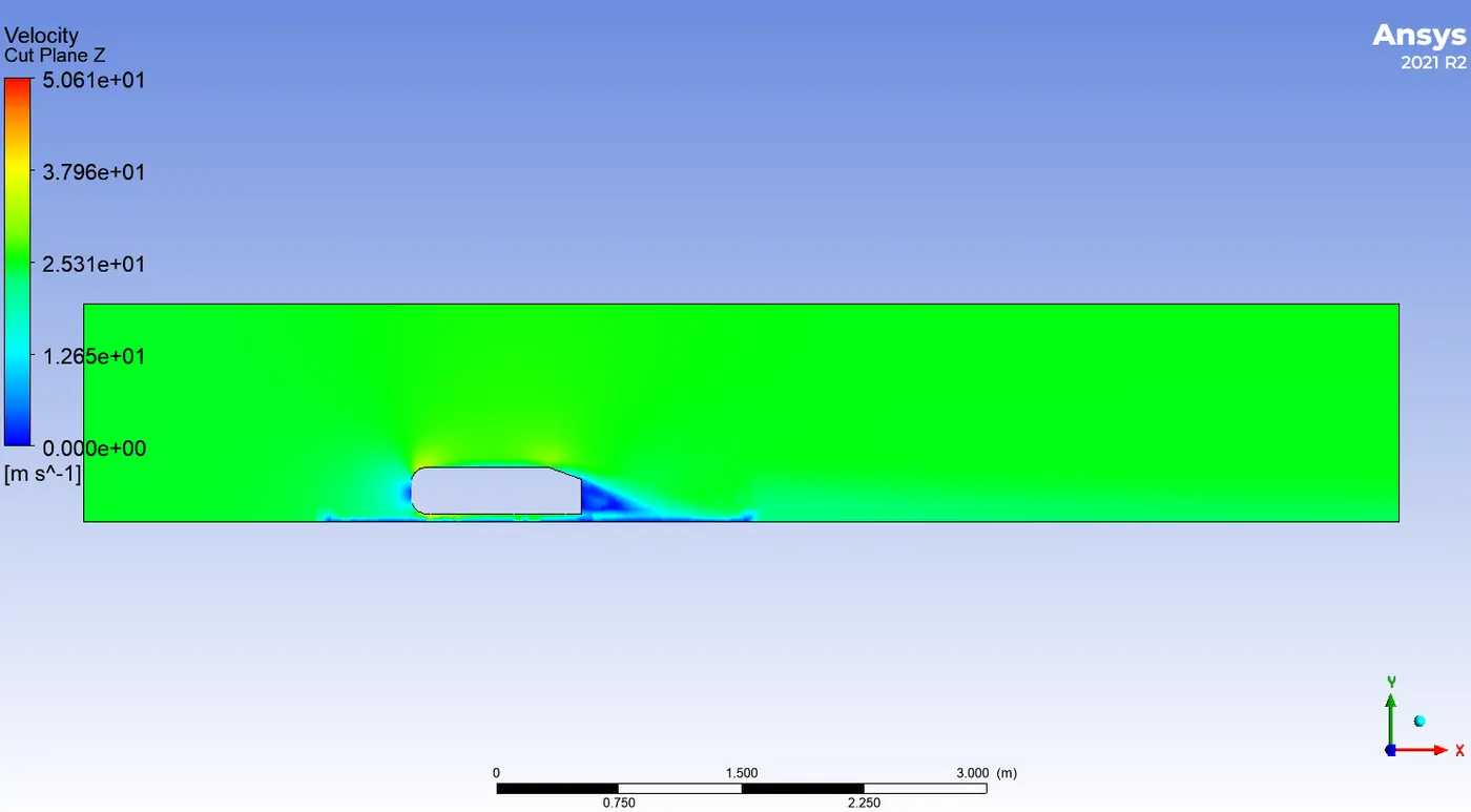
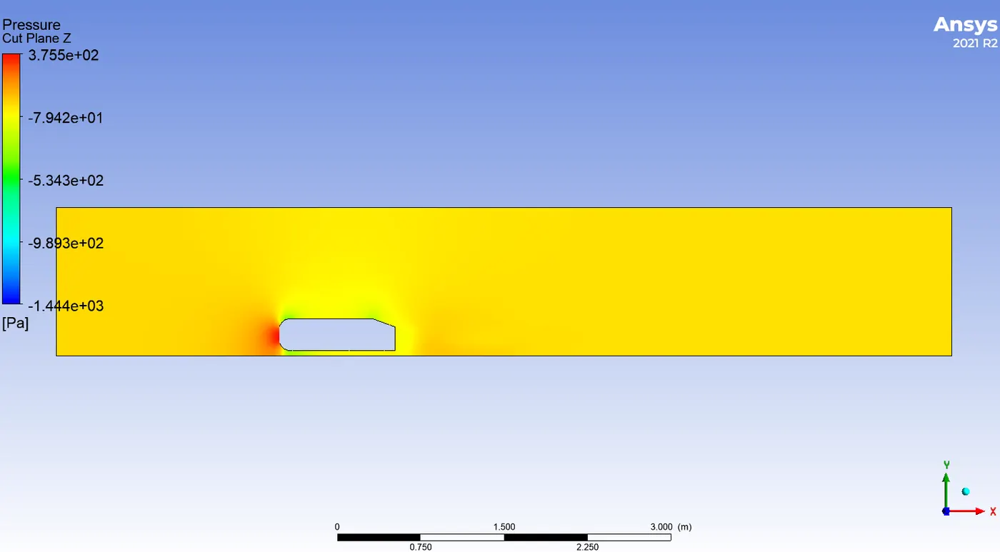
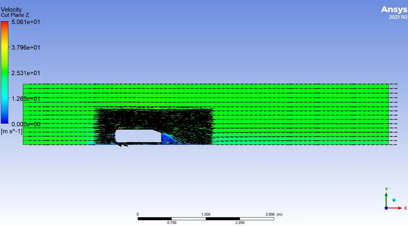
Refined Mesh Case I- Mesh Size- 100mm, Inflation layers- 5, Method- Multizone, Body Sizing- 50mm, Face Sizing- 5mm
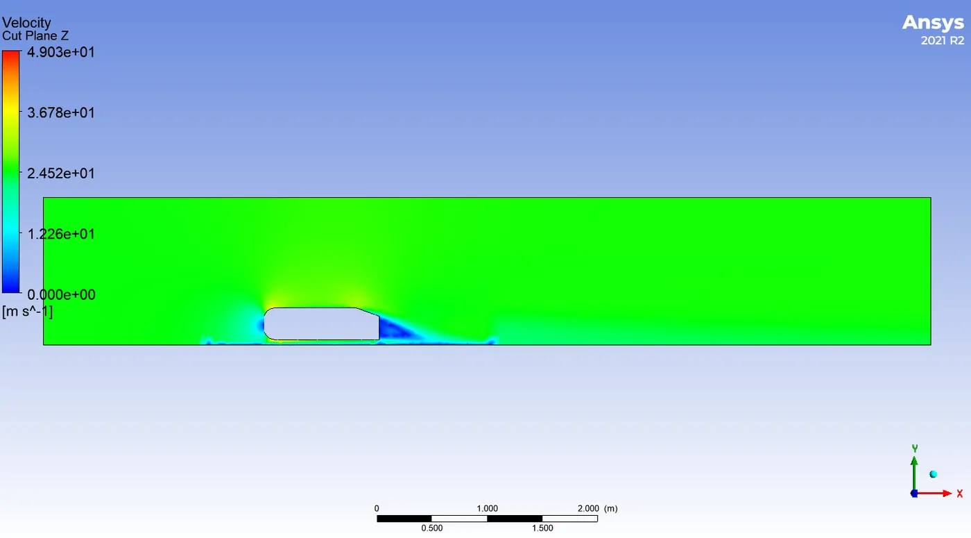
Refined Mesh Case II- Mesh Size- 100, Inflation Layers-6, Method- Multizone, Body Sizing- 40mm, Face Sizing- 5mm
Baseline Mesh-
Velocity Contour- Pressure Contour-
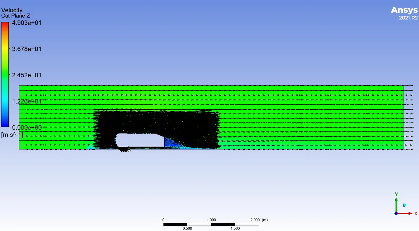
Vector Plot-
Refined Case I-
Velocity Contour- Pressure Contour-
Vector Plot-
Refined Case II-
Velocity Contour- Pressure Contour-
Vector Plot-
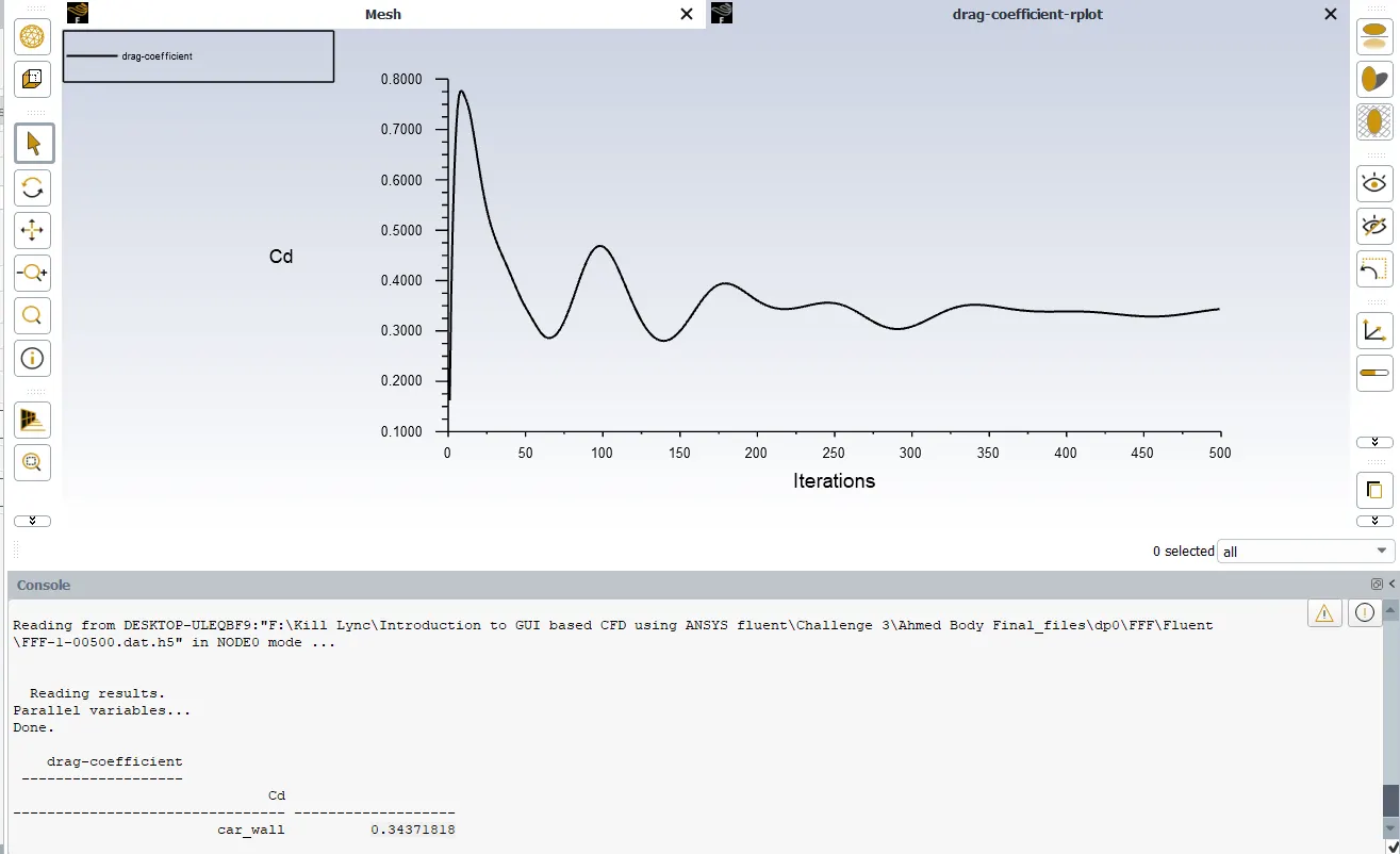
Refiend Case I-
Coefficient of Drag- 0.34371818
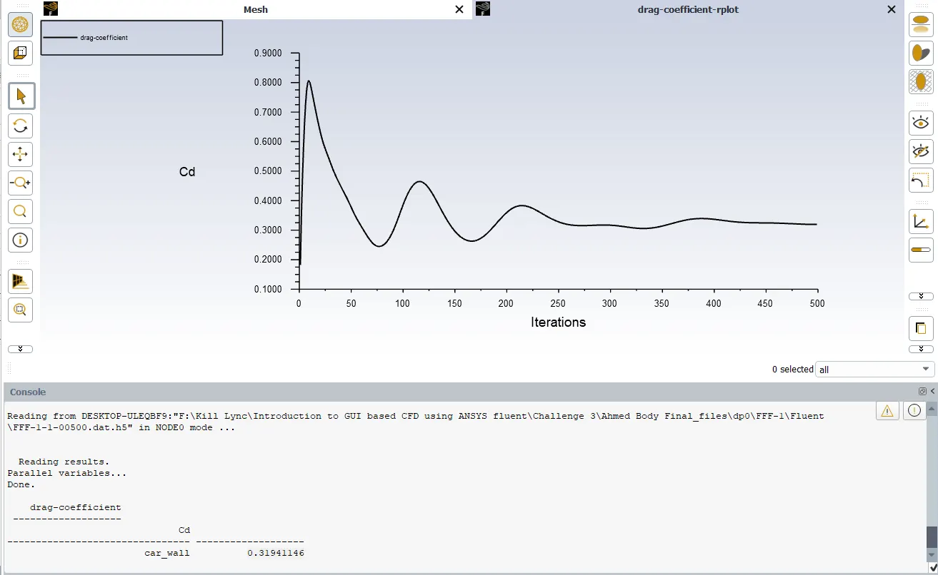
Refined Case II-
Coefficient of Drag- 0.31941146
Grid Independency test-
| Cases | Number of nodes | Coefficient of Drag | Coefficient of Lift |
| Baseline Mesh | 16277 | 0.3675637 |
0.2321175 |
| Refined Case I | 54856 | 0.34371818 | 0.26483643 |
| Refined Case II | 73704 | 0.31941146 | 0.29393095 |