Week 3 - External flow simulation over an Ahmed body.
EXTERNAL FLOW SIMULATION OVER AN AHMED BODY
AIM:
To simulate the external flow and to examine the flow behaviour around the ahmed body.
OBJECTIVE:
1.To Describe Ahmed's body and its importance.
2.Explain the reason for the negative pressure in the wake region.
3.Explain the significance of the point of separation.
4.To obtain drag coefficient and to examine the results for velocity and pressure contours and vector plots.
5.To perform grid dependency test.
Ahmed's body and its importance:
The Ahmed body represents a simplified, ground vehicle geometry of a bluff body type. Its shape is simple enough to allow for accurate flow simulation but retains some important practical features relevant to automobile bodies. This model describes how to calculate the turbulent flow field around a simple car-like geometry.
The airflow around the Ahmed body captures the essential flow features around an automobile and was first defined and characterized in the experimental work of Ahmed. Although it has a very simple shape, the Ahmed body allows us to capture characteristic features that are relevant to bodies in the automobile industry.
This model is also used to describe the turbulent flow field around a car-like geometry. People working in vehicle aerodynamics use Ahmed body to validate their numerical model because the experimental data from wind tunnel testing is available for Ahmed body. Once the numerical model is validated, it is used to design new models of the car.
The Ahmed body was described originally by S. R. Ahmed in 1984. Three main features were seen in the wake:
1. The A recirculation region that is formed as the flow separates at the top of the vertical back surface of the model
2. The B recirculation region that is formed due to the separation at the base of the model.
3. The c-pillar vortices that form as the vorticity in the side boundary layers roll up over the slant edges.
The wake was shown to be highly dependent on slant angle. For slant angles less than 12°, the flow remains attached over the slant. The flow is essentially two-dimensional and has low drag. Between 12° and 30° the flow becomes much more three-dimensional as the c-pillar vortices form. These reach maximum strength at 30°. The drag increases significantly as the low pressure cores act on the rear surfaces. Past 30° the flow separates fully off the slant. This results in a sudden decrease in drag and weaker c-pillar vortices.
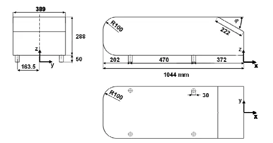
Fig.1.Geometry of the Ahmed body
[Taken from Article: Experiments and numerical simulations on the aerodynamics of the Ahmed body]
Reason for the negative pressure in the wake region.
The negative pressure is due to the velocity difference applied at a certain Reynold number and the rear angle, which at a low Reynolds number when this difference in pressure happens the wake obtained increases the drag due to the pressure drop behind the Ahmed body, which at a high Reynolds number due to the vortices generated it produces small amounts of pressure thrusting the body.
The air becomes almost stagnant as it strikes Ahmed body which results in air exerting very high pressure on the front face of Ahmed body. The airflow then gets divided between the upper and lower surface of the Ahmed body. The higher pressure air on the front surface accelerates as it travels over the curved nose surface of Ahmed body, causing the pressure to drop. This lower pressure creates lifts over the roof surface as the air passes over it. As the air continues to flow and make its way to the rear, a notch is created by the rear slant owing to flow separation, leaving a vacuum or low-pressure space which the air is not able to fill properly. The resulting lower pressure creates lift and the drag that then acts upon the surface area of the rear slant.
The significance of the point of separation.
Flow separation or boundary layer separation is the detachment of a boundary layer from a surface into a wake. Separation occurs in flow that is slowing down, with pressure increasing, after passing the thickest part of a streamline body or passing through a widening passage.
The point of separation defined by the Ahmed body and the flow, the alpha angle depending on which value is at it causes a change in the flow direction, forces required, lift on the body, induced drag due to “tip vortex”, at a critical value flow in slant stalls and reduced lift-reducing as well drag, all depending on the value of alfa and the Reynolds number.
PRE PROCESSING:
FOR DEFAULT CASE
Import the Geometry in ANSYS Spaceclaim
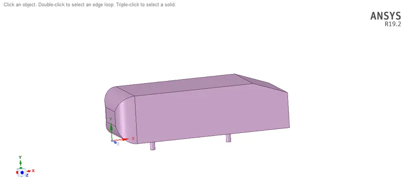
Creating Enclosure
Dimensions for creating the Enclosure
Prepare> Enclosure
Front offfset distance - 2m
Rear offset distance - 5m
Top offset distnce - 1m
Bottom offset distance - 0m
Side offset distance - 0.5 m
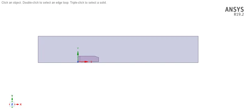
MESHING:
Run Mesh Generation using Default mesh criteria
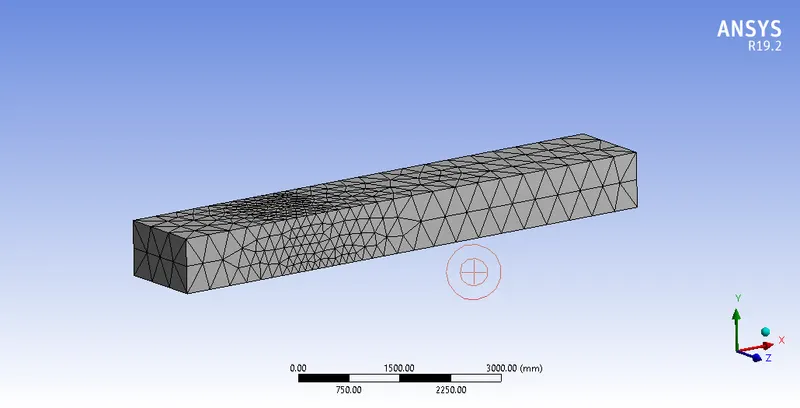
| Element Size | 410 mm |
| Nodes | 16346 |
| Elements | 82700 |
| Mesh Type | Triangular |
SOLVER SET-UP:
| Solver Time | Steady |
| Solver Type | Density based |
| Energy | off |
| Models | K-Omega SST |
| Material | air |
| Inlet-Velocity | 25m/s |
| Iterations | 500 |
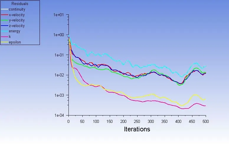
Residual plot:
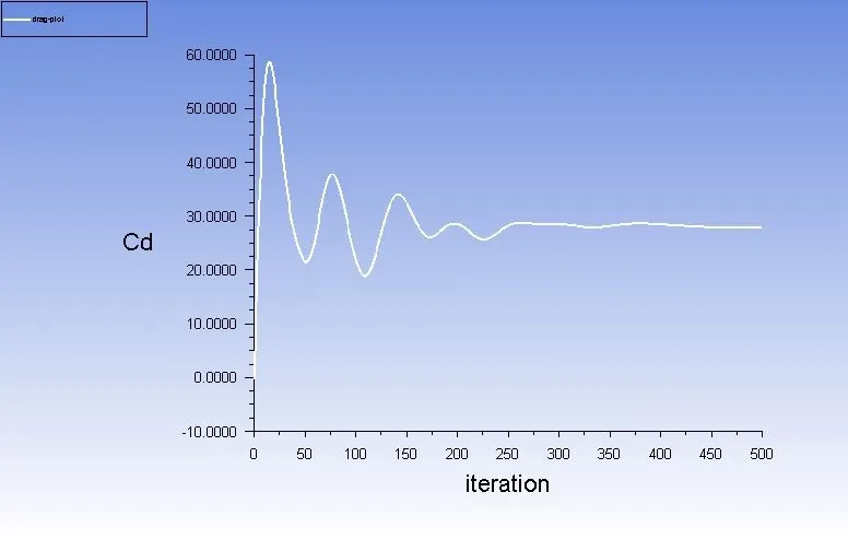
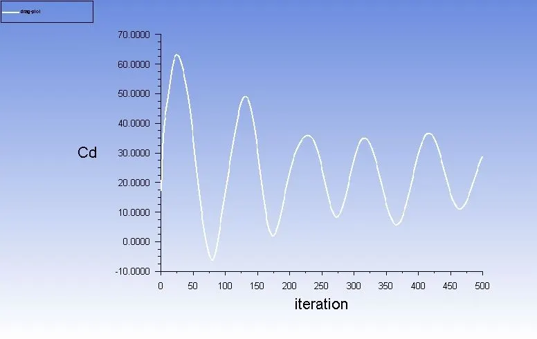
Coefficient of Drag Plot
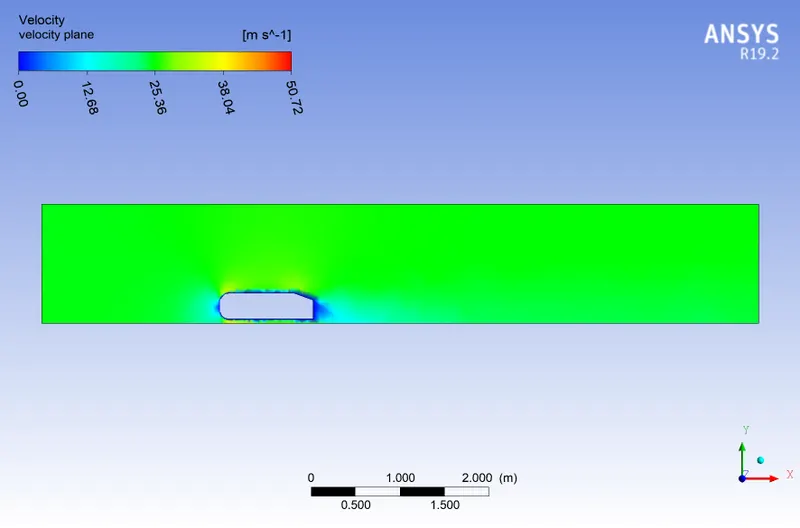
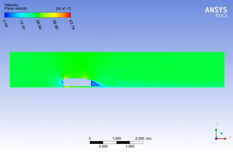
Velocity contour plot
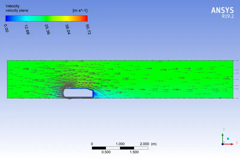
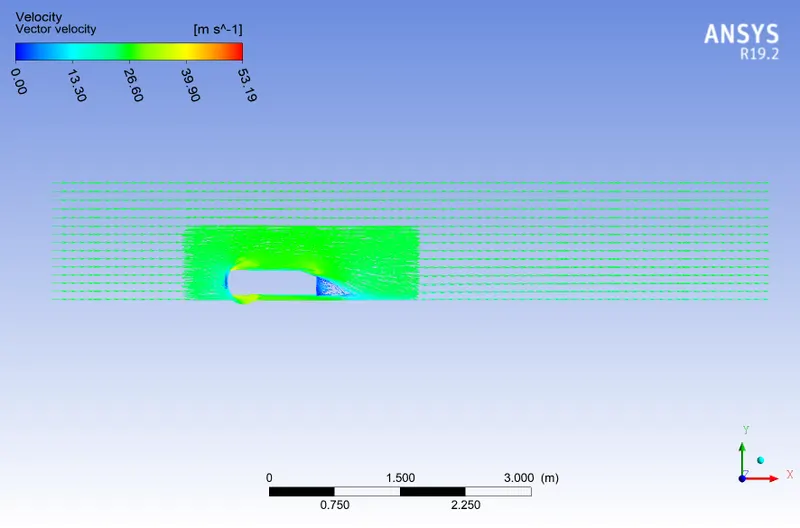
Velocity Vector plot
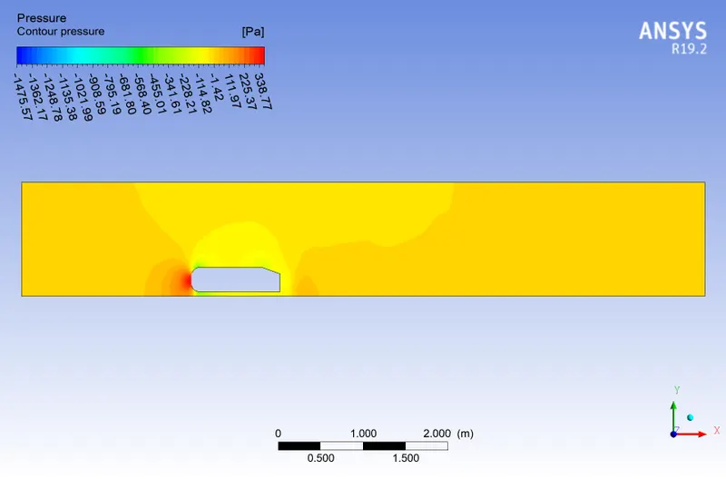
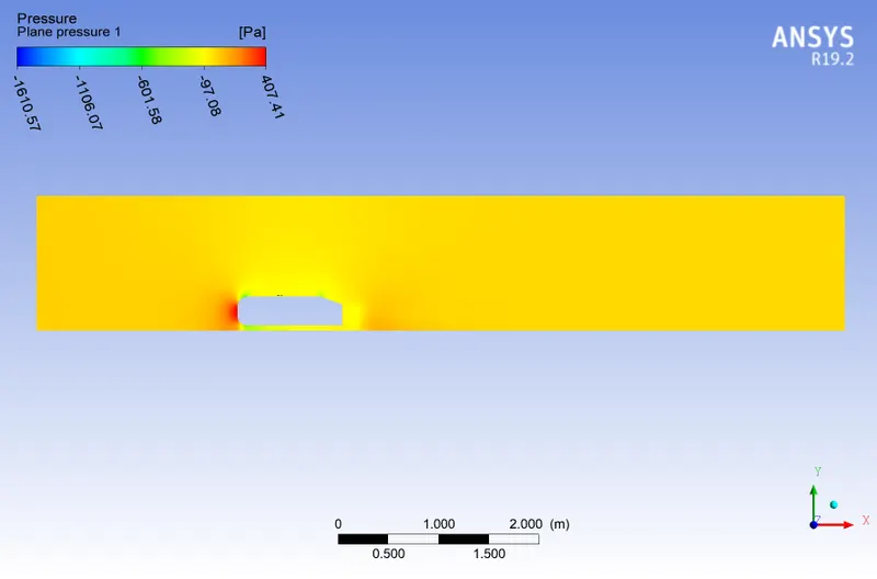
Pressure Contour Plot
FOR REFINED MESH CASE
Importing the Geometry
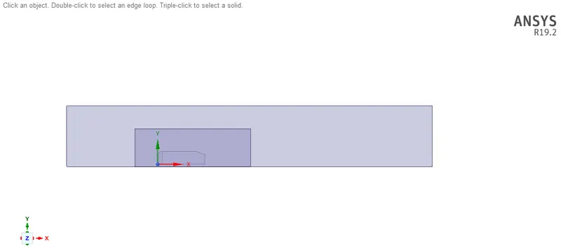
Creating Enclosure
Dimensions for creating the Enclosure
Prepare> Enclosure
Enclosre Large,
Front offfset distance - 2m
Rear offset distance - 5m
Top offset distnce - 1m
Bottom offset distance - 0m
Side offset distance - 0.5 m
Enclosure Small,
Front offfset distance - 0.5m
Rear offset distance - 1m
Top offset distance - 0.5m
Bottom offset distance - 0m
Side offset distance - 0.26 m
MESHING
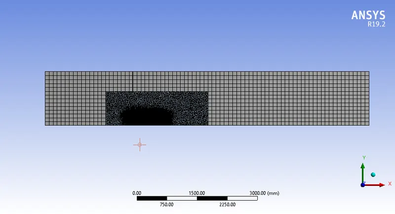
| Nodes | 16654 |
| Elements | 84443 |
| Method| Large Enclosure | Multizone (Hex Mesh) |
| Element Size | Large Enclosure | 100mm |
| Method| Small Enclosure | Triangular Mesh |
| Element Size | Small Enclosure | 10mm |
| Inflation Layers | 5 |
| Total Thickness | 13 mm |
SOLVER SET-UP
| Solver Time | Steady |
| Solver Type | Density based |
| Energy | off |
| Models | K-Omega SST |
| Material | air |
| Inlet-Velocity | 25m/s |
| Iterations | 500 |
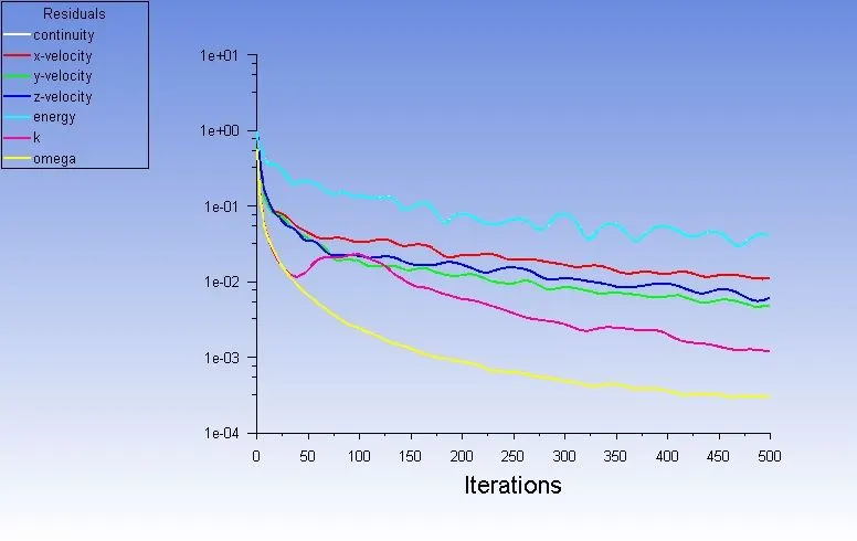
Residual plot,
Coefficient of Drag plot,
Velocity Contour plot
Velocity Vector plot,
Pressure Contour Plot
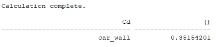
Coefficient of drag for Refined Mesh;
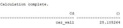
Coefficient of drag for Base mesh;
Conclusion;
Conclusion;
The simulation of flow over ahmed body is carried out for both coarse mesh and refined mesh and the results are plotted.
In conclusion, we observe that the flow over ahmed body with coarse mesh has less negative pressure at the rear (wake ) the recirculation is less whereas the drag produced is higher which results in abrupt changes, the increasse in drag is due to the high flow separation near the top walls of the car and this flow separation occurs due to the indefinite mesh around the ahmed body.
Whereas incase of flow over the ahmed body with refined mesh has a drag coefficient around 0.35 which is less. This is achieved by defining the inflation layers around the walls and creating an enclosure which basically holds refined mesh. By definig the inflation around the walls, we reduce the flow separation and the skin friction drag.The wake produced will reduce the overall efficiency and performance and this can be avoided by streamlining the body.
Link to download file:
https://drive.google.com/file/d/1iOzxkP9Agl-oUpo8PBLZSo3TKM7rXULs/view?usp=share_link