Week 3 - External flow simulation over an Ahmed body.
AIM:
To perform a grid independency test on the Ahmed body.
EXPECTED RESULT:
1. Velocity and pressure contours.
2. The drag coefficient plot for a refined case.
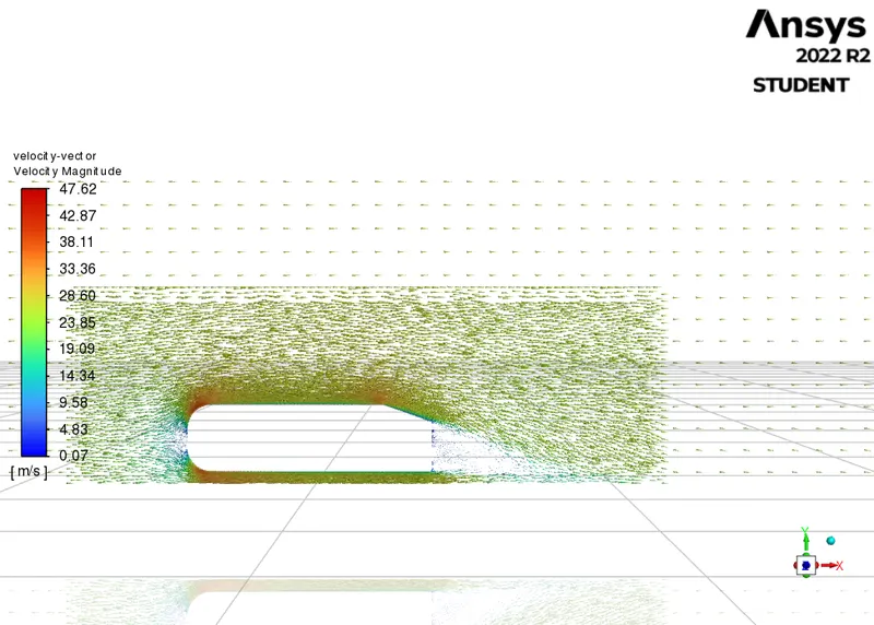
3. The vector plot clearly to showing the wake region.
4. Perform the grid independence test and provide the values of drag and lift with each case.
GIVEN DATA:
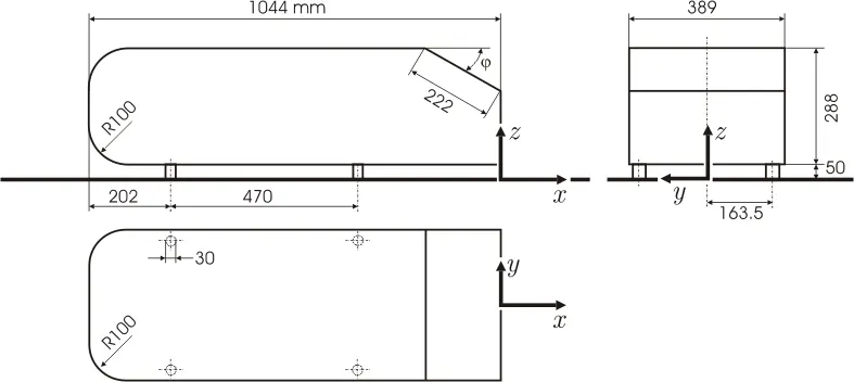
This is the sketch drawing:
AHMED'S BODY AND IMPORTANCE:
Ahmed is a simplified car body that was first created by S.R Ahmed. This shape provides a model to study geometrical effects on the wakes of ground vehicles. This is the kind of baseline geometry for automobile bodies. The airflow around Ahemd's body captures the essential flow features around an automobile and describes how to calculate the turbulent flow field around a simple car-loke geometry using the turbulent, flow, K-epsilon interface. People working in vehicle aerodynamics use Ahemdbody to validate their numerical model because of the experimental data for Ahemd body. Once the numerical model is validated, it is used to design new models of the car and for faster calculation and comparison of analytical results.
Wake Region:
When the air moving over the vehicle is separated at the rear end, it leaves a large low-pressure turbulent region behind the vehicle which is known as the wake. This contributes to the formation of pressure drag which affects the vehicle's performance.
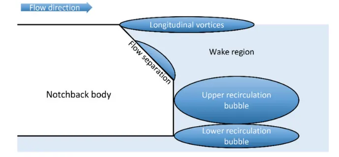
The negative pressure can be observed in this wake region because, at the rear end, the vicious fluid gets detached from the body of the vehicle causing the pressure to drop below zero.
Point of Separation:
The point of separation will occur when there is a discontinuity in the surface. The point of separation occurs in Ahmed's body at the top rear end of the body where a pressure drop is observed. The recirculation region happens beyond the point of separation.
SIMULATION PROCEDURE:
CASE_I: BASELINE MESH (0.08 MILLION CELSS)
Geometry space claim uplod
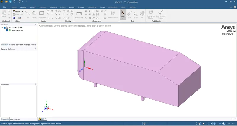
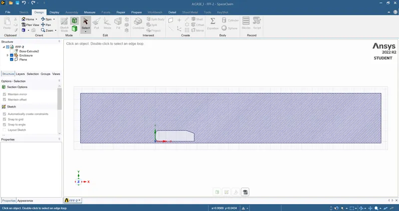
- For baseline simulation, a single wind tunnel is created around the body. The Enclosure dimensions are shown below,
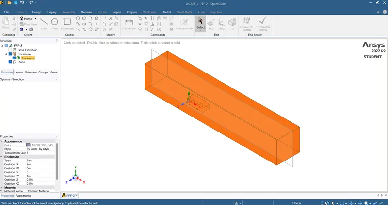
- The Ahmed's body is suppressed and the cross-section view is shown below,
MESHING PROCESS:
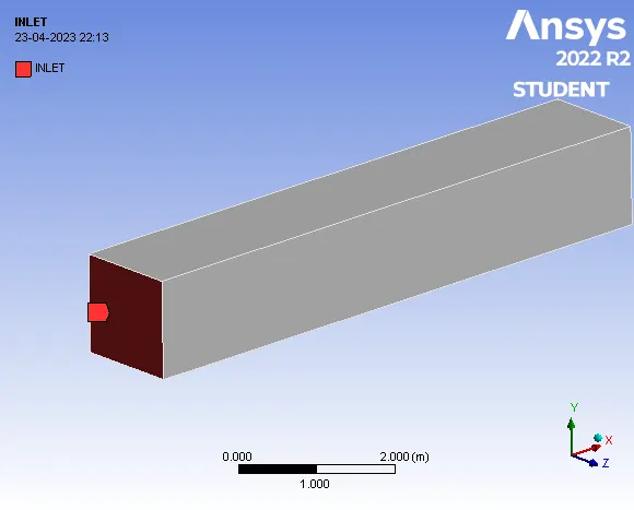
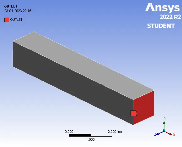
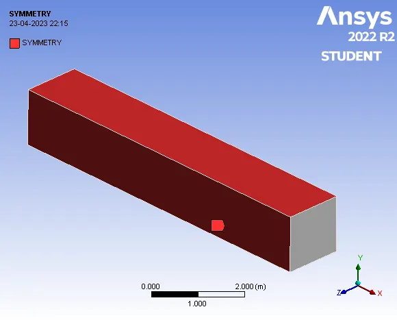
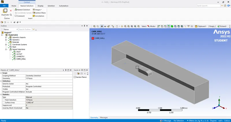
- The named selections are created as follows,
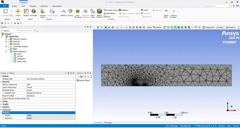
- For the baseline simulation, we use the default mesh size. Generate Mesh,
Setup - Fluent:
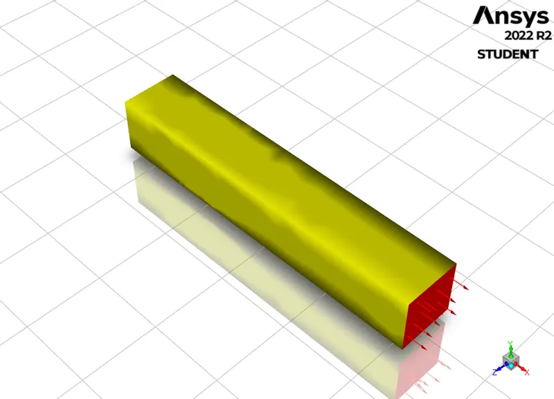
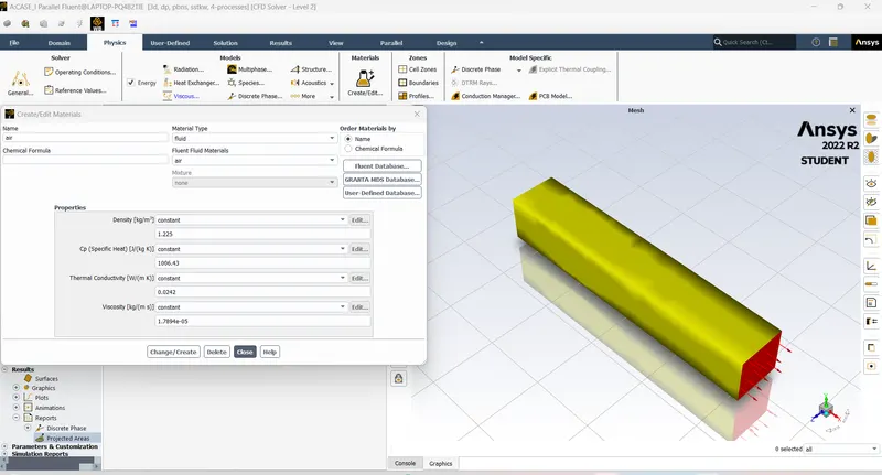
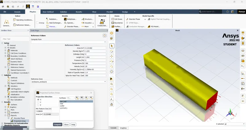
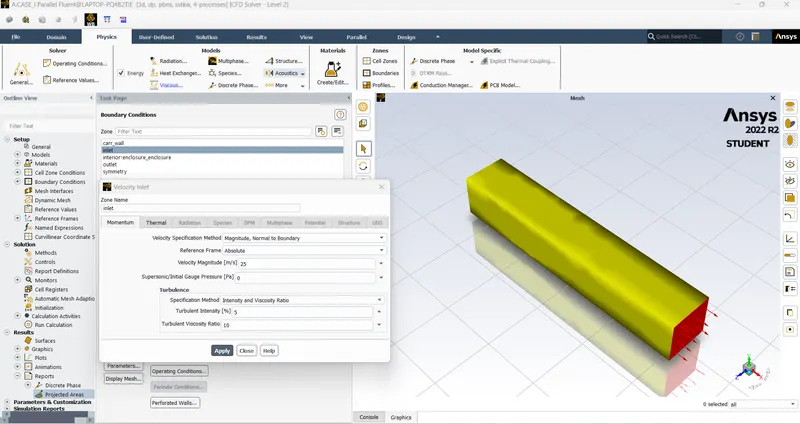
- The meshed geometry is loaded in ANSYS Fluent,
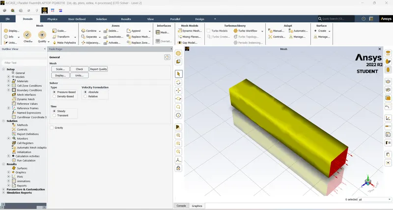
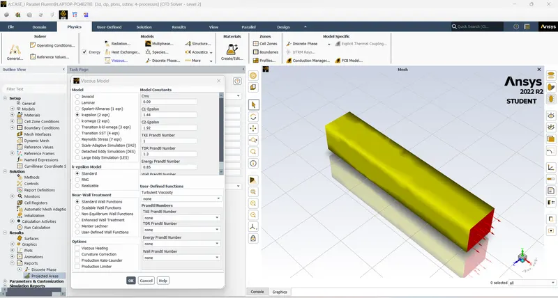
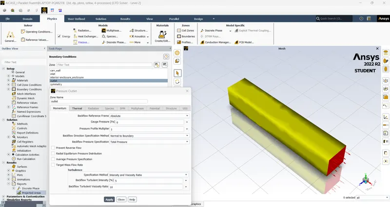
- For baseline simulation, the Density-Based solver is used. The steady state is considered,
viscous model
Simulation - Fluent:
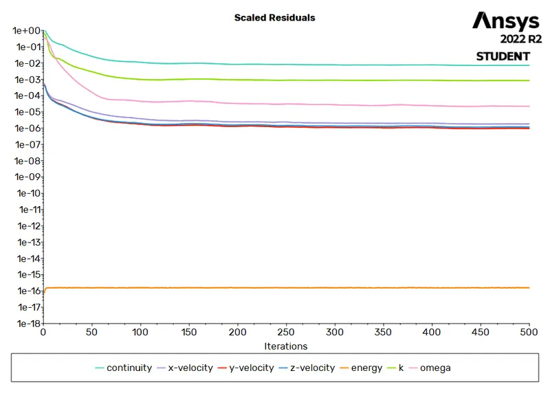
- The simulation is performed for 500 iterations.
Results - PostProcessing:
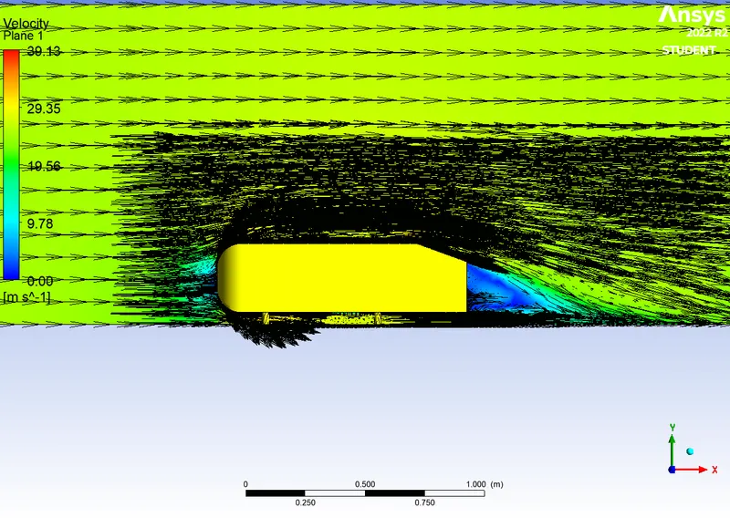
- The velocity and pressure contours are generated here.
RESIDUALS PLOT:
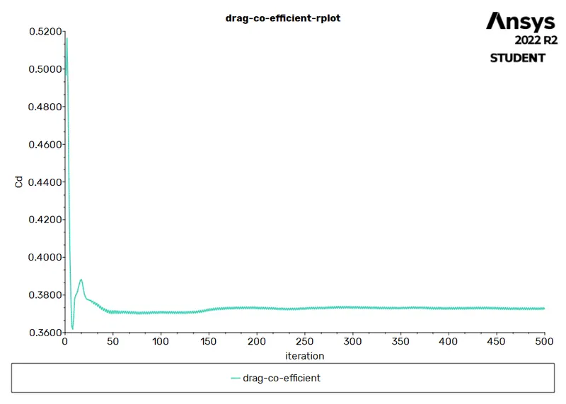
DRAG CO_EFFICIENT PLOT:
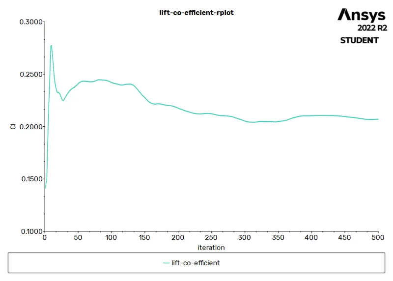
LIFT CO_EFFICIENT:
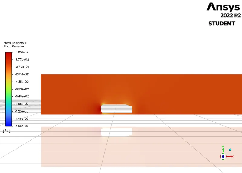
PRESSURE CONTOUR:
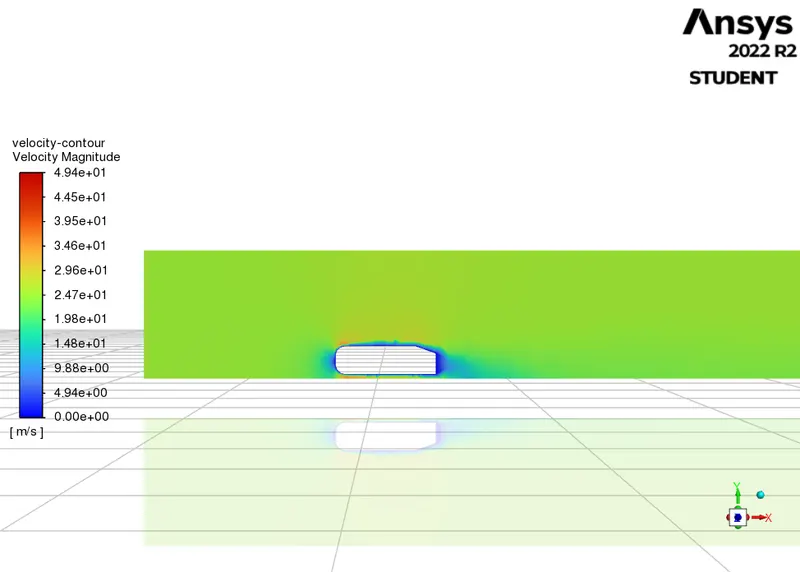
VELOCITY CONTOUR:
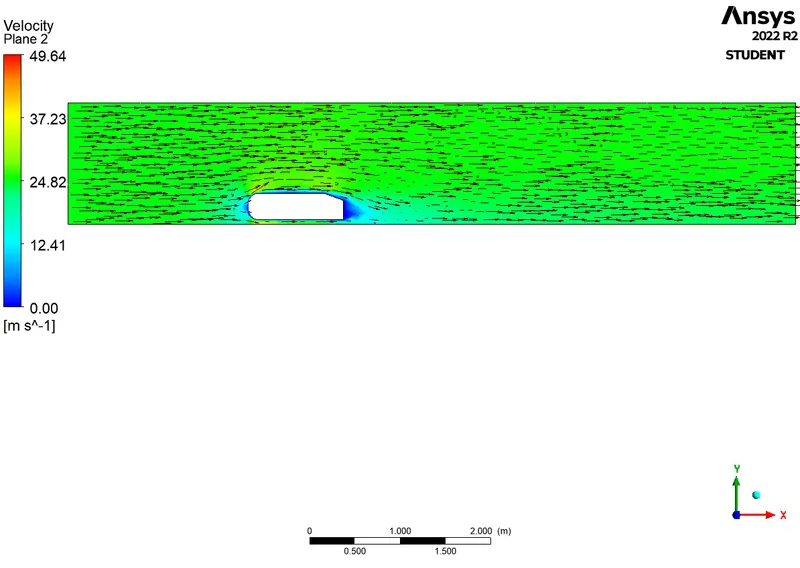
VELOCITY VECTOR PLOT:
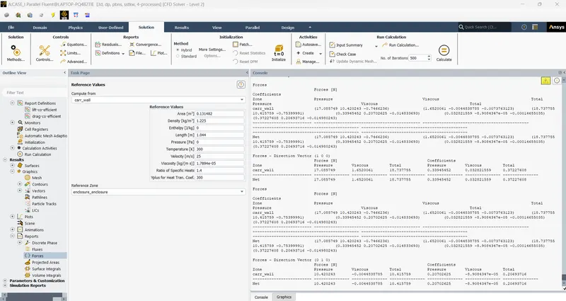
RESULT PRINT:
---------------------------------------------------------------------------------------------------------------------------------
CASE_II -FINE MESH ( 0.18 million cells):
Geometry - Spaceclaim:
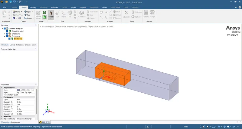
- The geometry is the same as the baseline simulation. the only change here is, there are 2 enclosures in this simulation. The 2nd enclosure dimension are given below,
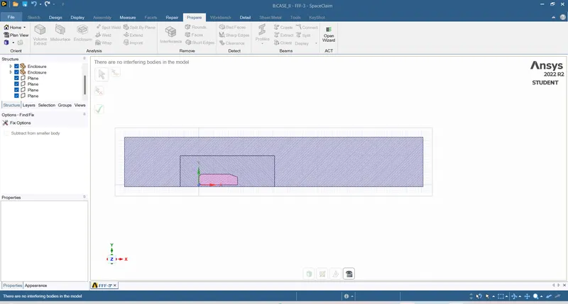
- The interference is removed using the interference tool in SpaceClaim to avoid mesh overlapping,
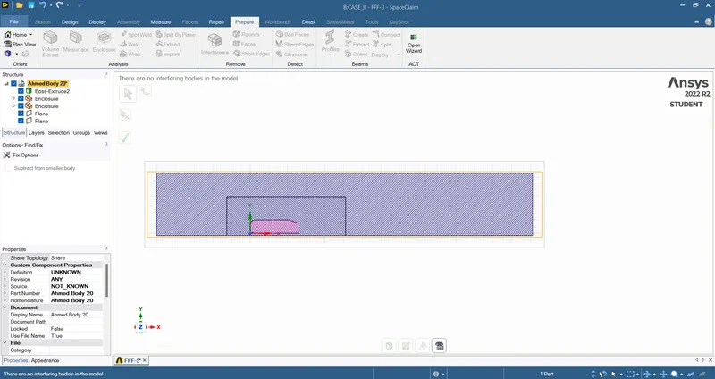
SHARE TOPOLOGY:
Mesh - Meshing:
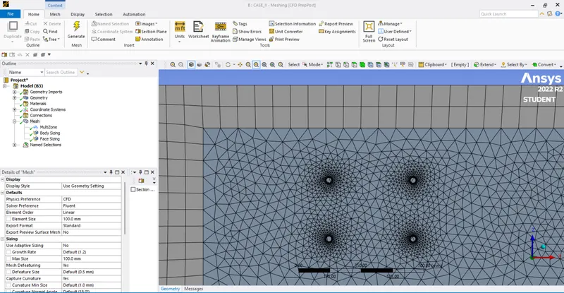
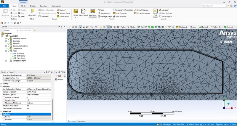
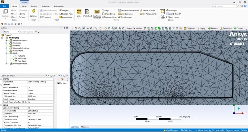
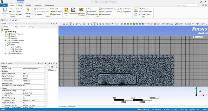
- Method- The highest quality of the mesh, the hexahedral mesh is used for the external enclosure. the element size = 100 mm.
- Sizing- For the inner enclosure sizing is performed. The element size = 50 mm.
- Face sizing- The four stands(wheels) are face sized to retain the cylindrical shape. The element size = 5 mm.
- Inflation layer- The car_wall is selected for inflation layers. the number of divisions = 6, maximum layer thickness = 12.5 mm.
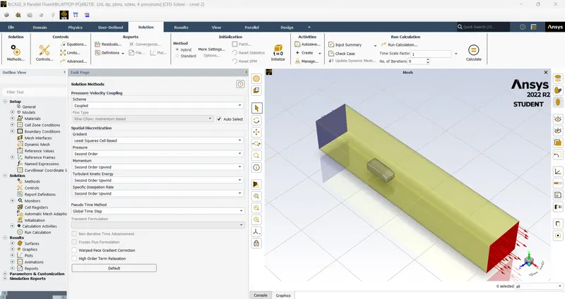
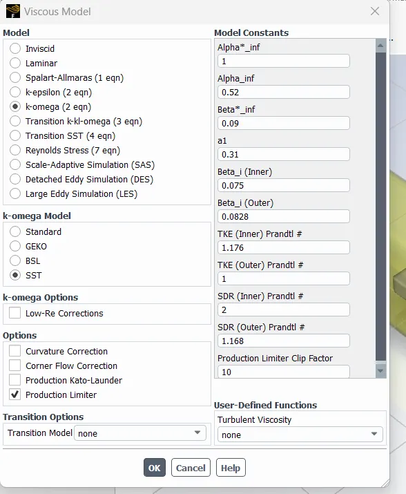
Setup - Fluent:
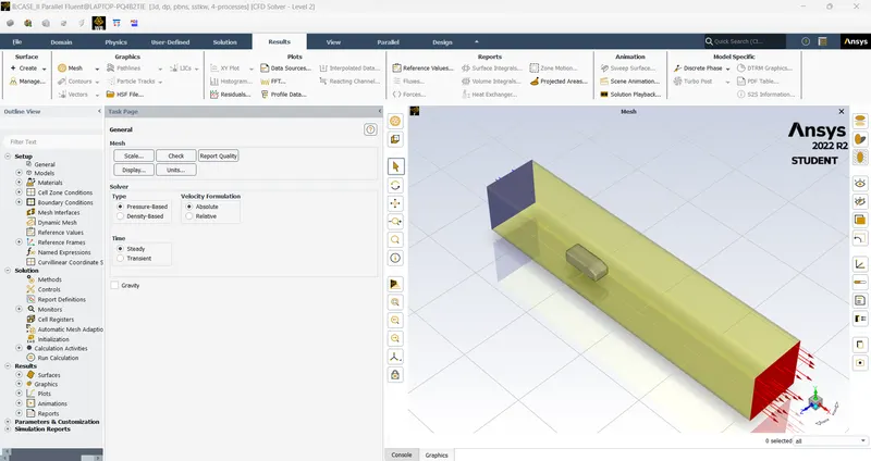
- The meshed geometry is loaded in ANSYS Fluent,
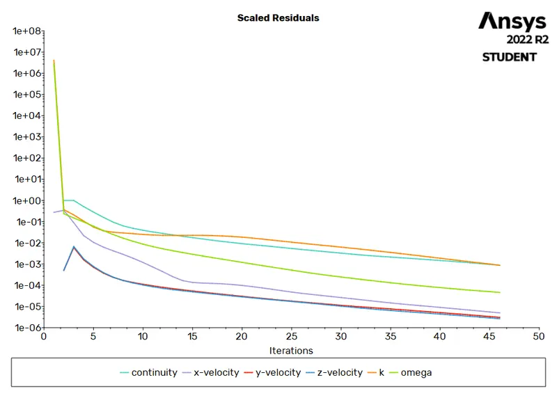
RESIDUAL PLOT:
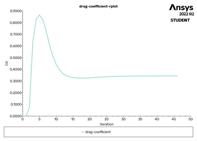
DRAG CO_EFFICIENT:
LIFT CO_EFFICIENT:
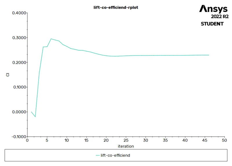
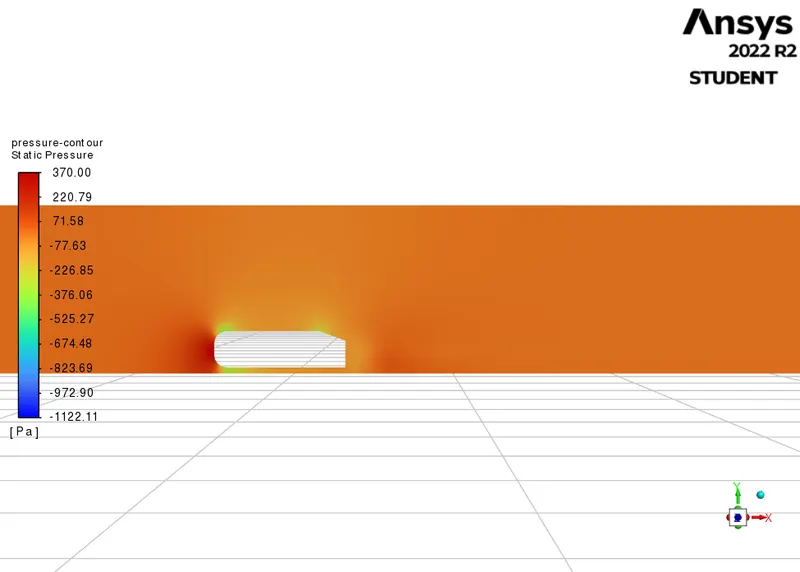
PRESSURE CONTOUR:
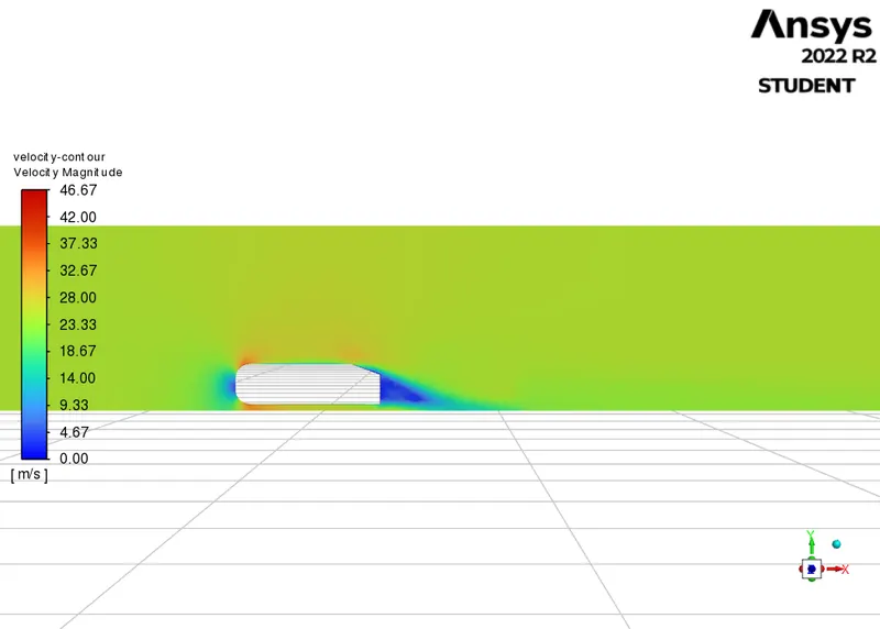
VELOCITY CONTOUR:
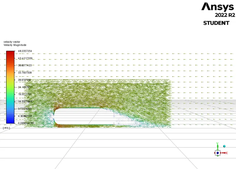
VELOCITY VECTOR:
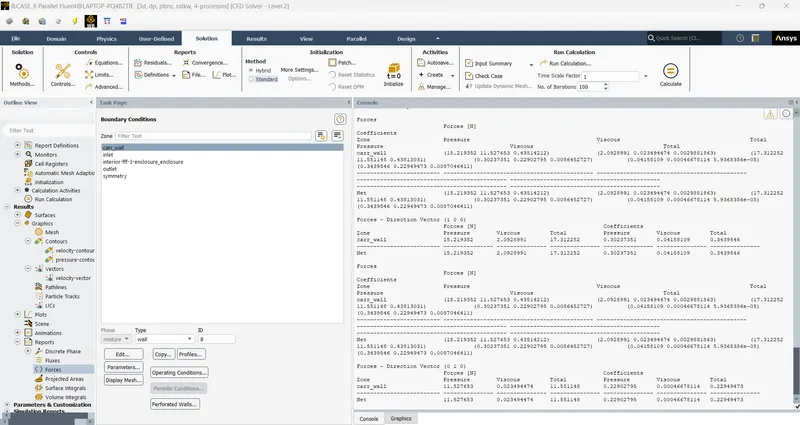
PRINT RESULT:
CASE_III -FINER MESH ( 0.35 million cells):
- The only changes to be made are as follows,
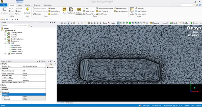
Mesh - Mesher:
- Face sizing- After hiding the outer planes, using the box select tool the car_wall is selected for face sizing. The element size = 14.5 mm
RESULTS for finer mesh simulation:
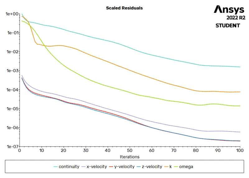
RSIDUALS PLOT:
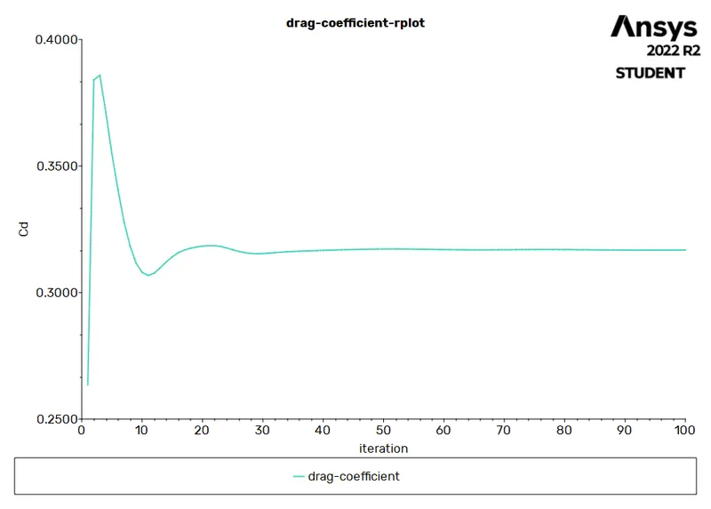
DRAG CO_EFFICIENT:
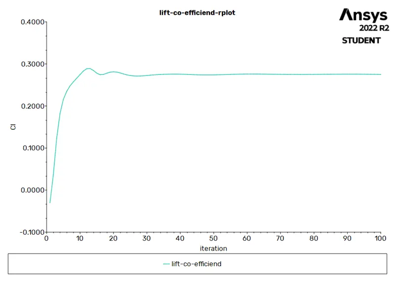
LIFT CO_EFFICIENT:
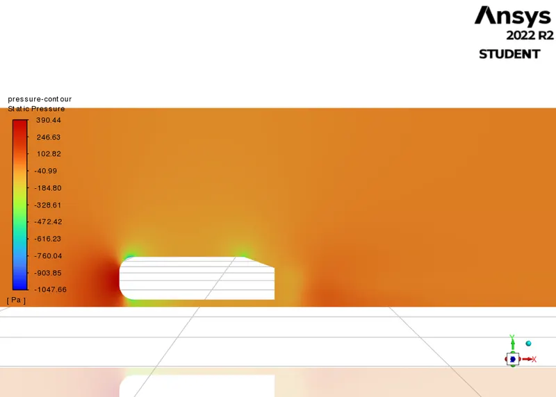
PRESSURE CONTOUR:
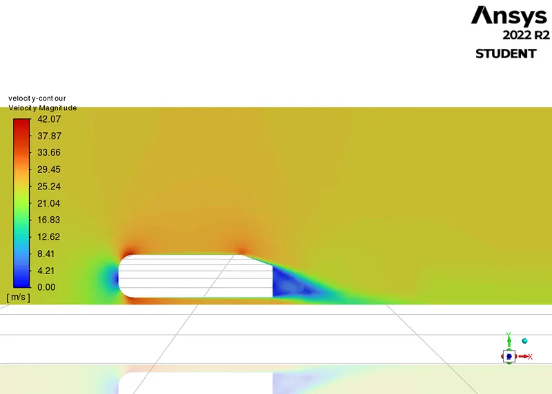
VELOCITY CONTOUR:
VELOCITY VECTOR PLOT:
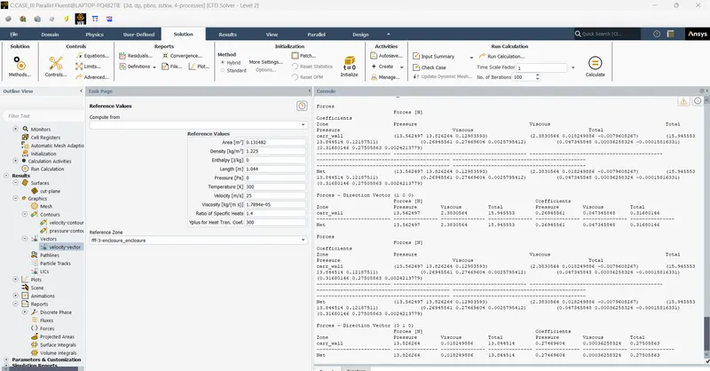
PRINT RESULT:
CASE _IV-SPLIT GEOMETRY:
Geometry - SpaceClaim:
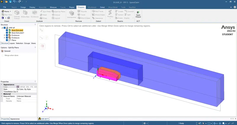
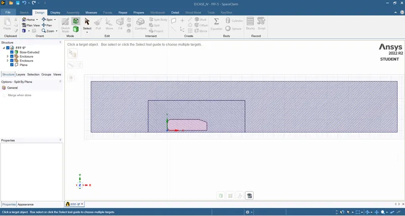
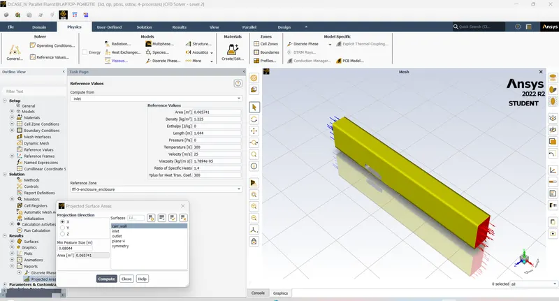
- As the Ahmed body is symmetrical along the z-axis, half of the geometry can be removed to reduce the number of mesh cells.
- Use the split body tool to cut the geometry along the z-axis.
MESHING:
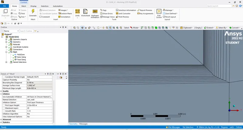
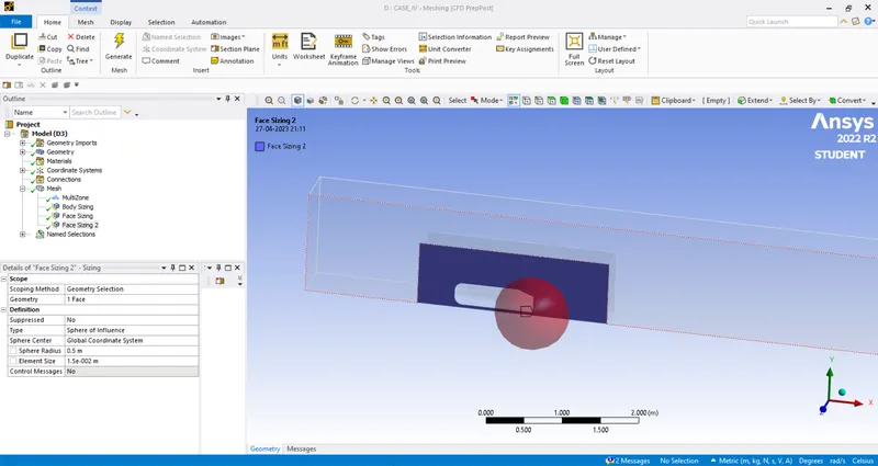

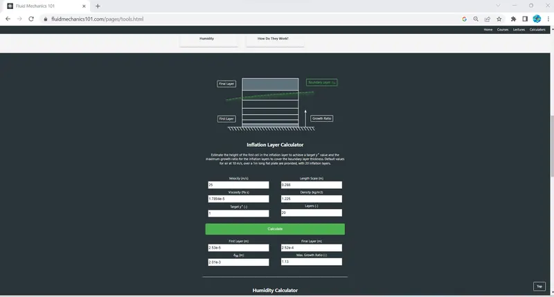
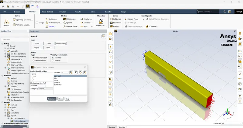
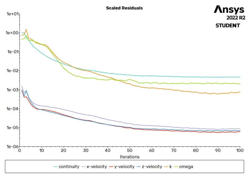
RESIDUALS PLOT:
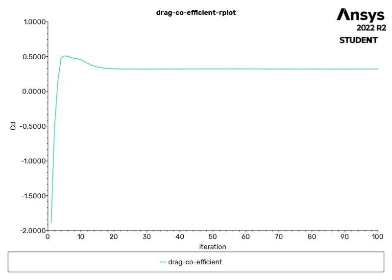
DRAG CO EFFICIENT:
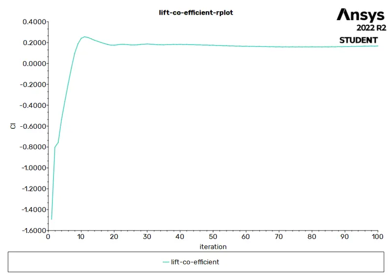
LIFT CO EFFICIENT:
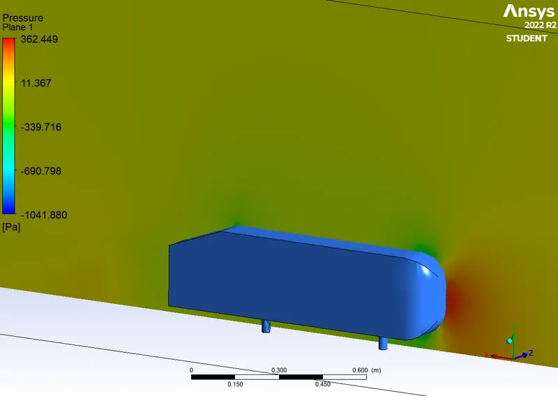
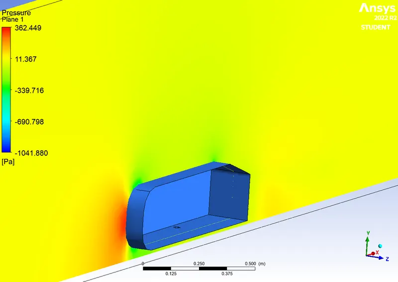
PRESUURE CONTOUR:
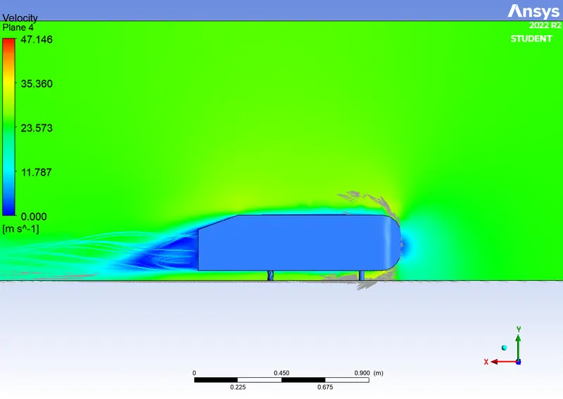
VELOCITY CONTOUR:
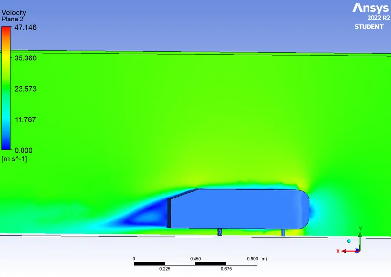
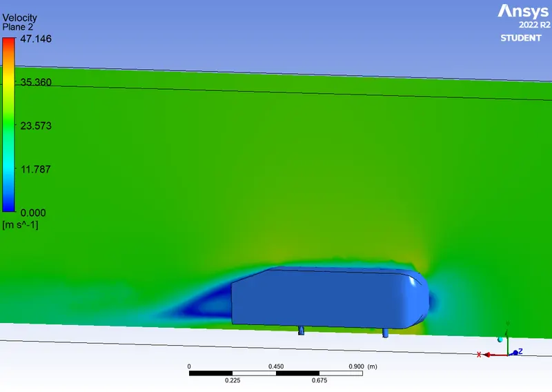
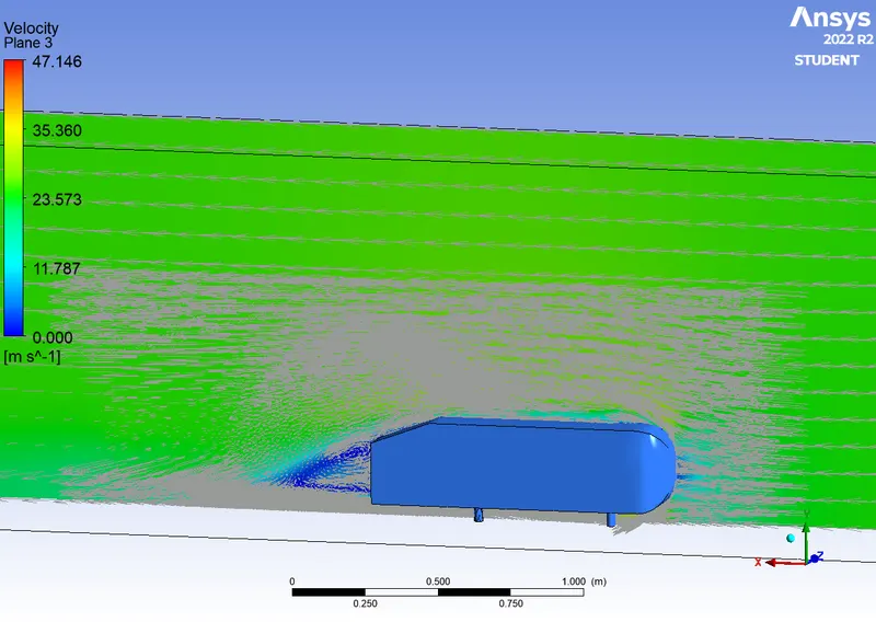
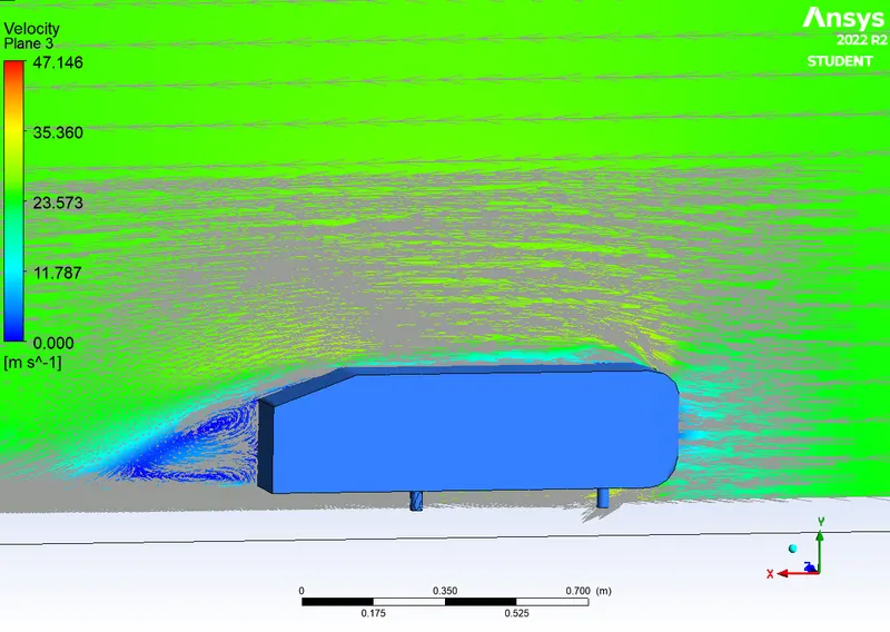
VELOCITY VECTOR:
VELOCITY STREAMLINE:
RESULT PRINT:
OBSERVATION:
Pressure plots:
- High pressure can be observed in the frontal area of the body due to the direct impact of the high-velocity fluid.
- In the rear top end of the body, the point of separation can be observed. This occurred as there is a discontinuity of surface in the path of fluid flow.
- Due to this discontinuity of surface, a low-pressure region is created behind the body thereby pushing the high-pressure air towards it changing the direction of the flow. This region is called the wake region.
- The wake region is formed beyond the point of separation.
- The negative pressure in the wake region is primarily because there is no flow in that region.
Velocity plots:
- As Ahmed body is static, the velocity of the body is zero.
- Due to no-slip walls, the velocity of fluid flowing near the car walls is low.
- The fluid circulation in the wake region can clearly be observed in the vector and streamline plot.
- The fluid can't escape the wake region as the velocity of flow around this region is high resulting in recirculation.
Grid independence test:
| MESH | TURBULENCE MODEL | CELL COUNT | DRAG COEFFICIENT | LIFT COEFFICIENT |
| BASELINE | K-EPSILON | 0.08 MILLION | 0.372 | 0.206 |
| FINE | K-OMEGA(SST) | 0.2 MILLION | 0.343 | 0.226 |
| FINER | K-OMEGA(SST) | 0.35 MILLION | 0.316 | 0.275 |
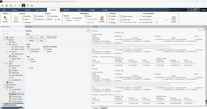
| SLICED GEOMETRY | K-OMEGA(SST) | 0.44 MILLION | 0.322 | 0.168 |
- From performing the grid independence test, it is inferred that the sliced geometry method was best suited for this problem.
- The Drag coefficient value of sliced geometry mesh seems closer to the experimental value of 0.33
- Also, since the geometry is sliced, the number of cells decreased almost by a factor of 2 paving the way for very high mesh refinement.
y+ value:
- Due to the proper usage of the y+ to calculate boundary layer inflation values, accurate results can be observed at the boundaries in sliced geometry plots than in other mesh plots.
CONCLUSION:
- The external flow simulation over the Ahmed body was conducted and the wake region was clearly visualized using Vector, streamline, and Contour plots.
- The coefficient of drag and coefficient of lift were estimated.
- The point of separation and its influence was studied.
- The grid Independence test was performed and an optimal grid condition was found.