Week 3 - External flow simulation over an Ahmed body.
EXTERNAL FLOW SIMULATION OVER AN AHMED BODY
INTRODUCTION (Ahmed Body & It's Importance)
The Ahmed body was at first put forward by Ahmed et al. (1984). is a general car model which is used by the automotive industries (Morel (1978), Good and Garry (2004), Guilmineau and Chometon (2009), Heft et al. (2012) and Huminic and Huminic (2012)), to examine the wake forces and dynamics which is experienced in a verity of configurations. The Ahmed body is designed to have a smooth-edged front end with a flat roof and a flat bottom section and an angled back slant which basically acts as the rear window of a car and ending with a vertical base. The back-slant angle which is commonly designated as ϕ is very critical to the flow patterns which are fashioned at the near wake region and subsequently has an impact on the aerodynamic forces which act on the body. Car companies makes numerous attempts to develop modified designs to effectively reduce the aerodynamic drag force which occurs at the rear end without putting any constraints in the stability, comfort and safety of the passengers. The aerodynamic drag of road automobiles is firmly connected to the vehicle’s wake downstream flow. The separation zone size and the drag force FD directly rest mainly on the position of flow separation over the Ahmed body. Subsequently, comprehensive facts regarding the wake flow characteristics and its connection with the geometry of body is essential for a successful design of upcoming future cars. The application of Computational Fluid Dynamics (CFD) in determining fluid flow pattern has been observed to be very common among researchers in the present days. CFD modeling in determining flow line of fluid around the Ahmed body has been utilized since the early 21st century. In many open literatures, the CFD application in determining air flow pattern and the changes in flow motion with altering geometry of the Ahmed body have been found. Certain modifications in the Ahmed body aids researches and designers to determine the effect of modification on the resultant drag and lift force which can be calculated using CFD modeling. The chief purpose of automotive aerodynamics is the reduction of drag, lessening noise emission, increasing fuel economy and eliminating unnecessary lift forces and other origins of aerodynamic unsteadiness which arises at high speeds.
The conventional Ahmed reference model has been considered as the standard model in this research work for carrying out numerical simulations for researching on the aerodynamic parameters. The Ahmed body has alike featured like a general car and is broadly utilized for authentication of new codes in the automobile industry. This simple geometric model has a length of 1.044-meter, height of 0.288 meter and a width of 0.389 meter. It consists of cylindrical legs of 0.5-meter radius attached to the bottommost part of the body. The rearmost surface has an inclination of 20 degrees. Ahmed body characterizes the simplified geometry of a ground vehicle as a bluff body type. Its geometry is adequate enough for precise flow simulation and retains few vital practical features relevant to cars. This model aids engineers and designers to generate turbulent flow field surrounding the simple car model by the use of k-epsilon model. In spite of neglecting quite a few numbers of features of a real car like rough underside, rotating wheels, surface projections etc. The Ahmed body generates the crucial features of flow pattern around a car for instance flow impinge-mentation and the displacement around the nose, relative uniform flow of air around the middle portion and flow separation along with the wake generation at the rear. Since the Ahmed body is easy to model, it can be effortlessly utilized for researching various properties like turbulence, drag coefficient, wake region, lift forces, velocity magnitude at various regions of the car, magnitude of pressure around the car which helps in determining what will be resistance, fuel efficiency etc. of the car thereby providing designers a clear idea on which region needs to be optimized for better effectiveness. The main objective of this study being stimulation of turbulent flow within the wind tunnel and around the Ahmed body to capture the flow pattern at the rear and wake region. A local refinement of mesh inside the concerned body is done with necessary body and face sizing’s of the parts of the Ahmed body to generate well defined plots for pressure and velocity contours and its grid dependency test is the primary focus of this report.
REASON FOR THE NEGATIVE PRESSURE IN THE WAKE REGION
The flow behind an object separates from the surface and creates a highly turbulent region behind the object, called the wake. The pressure inside the wake region remains low as the flow separates and a net pressure force (pressure drag) is produced. In other words, due to the production of pressure drag being produced from flow separation, the pressure in the wake region is low. This is what is causing the vacuum.
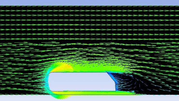
The streamlines in the wake region can convince us about the drag behind the vehicle. We have two regions behind the vehicle moving in -ve x-direction: (a) Wake region and (b) the core flow (in the +ve x-direction) adjacent to the wake region where the fluid particles are moving with high velocity. Since the core region particles are moving at high velocities, the pressure is low in that region. However, in the wake region, we have vacuum pressure i.e., relatively much lower pressure. After flow separation after a certain distance, the fluid particles get into the wake region and try to rush towards the rear surface of the vehicle. The particles near the rear surface may either be moving upwards or otherwise curved towards the +ve x-direction. If we draw the streamlines near the rear surface of the vehicle we can observe that the x-velocity component can either be zero or in the +ve x-direction only. Hence, the resultant force can be either zero or a drag force.
SIGNIFICANCE OF THE POINT OF SEPARATION
The position at which the boundary layer leaves the surface of a solid body. It may occur with the laminar flow (laminar separation) or when the boundary layer is turbulent (turbulent separation). Separation is sometimes followed by reattachment of the flow.
The separation point is the point where the air stops "sticking" to an object that is moving through the air. When an object is moving through the air, the air molecules push back on it and resist the object's movement - this resistance is called pressure drag. As the air flows around the object, it "sticks" to the object, forming what is known as the boundary layer. This "attached flow" is flowing very smoothly. The point on the body where the boundary layer lifts off the surface is called the separation point. When the air flow separates off the surface, the pressure drag usually increases.
STEPS USED FOR SIMULATIONS

Click on red encircled "Workbench 2021 R2" as shown in the above image to start the simulation.
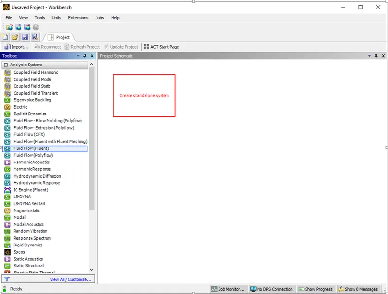
Click On Fluid Flow (Fluent) under Analysis Systems and drag it to create a standalone system.
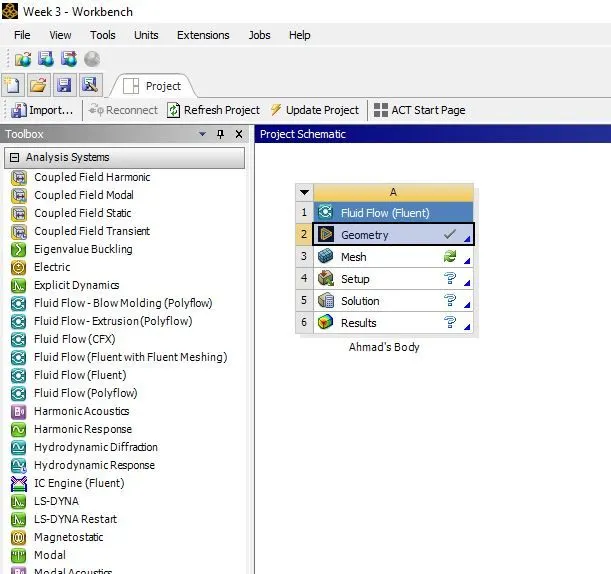
Rename the Project by using the left click and then click the Geometry.
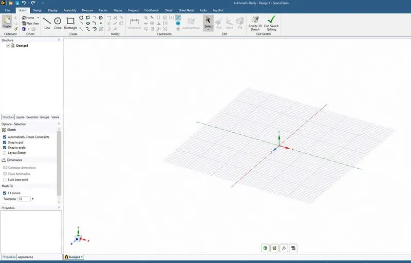
On clicking the geometry, the Space Claim window opens as shown in the above image.
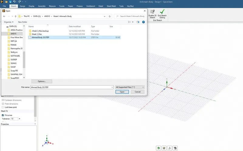
Open the dowloaded Ahmed Body 20.STEP file as shown in the above image.
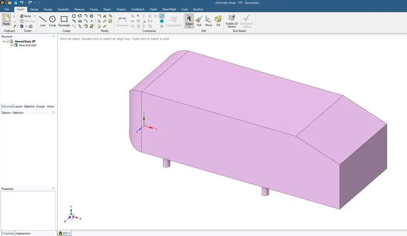
The above image represents the screen after opening the image in Space Claim.
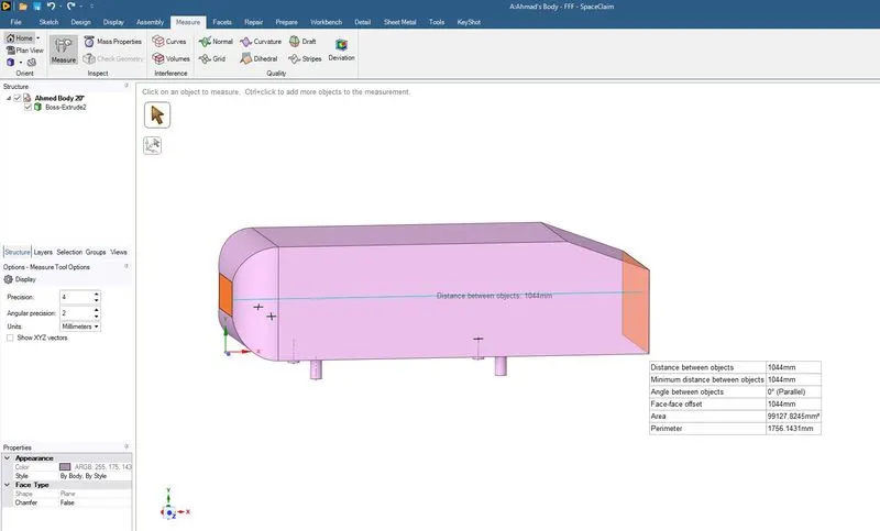
THe above step is used to find the length of the ahmed body.
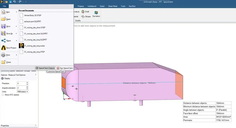
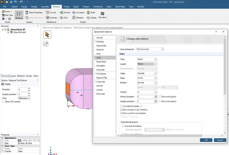
The above two images helps us the to change the units of measurement.
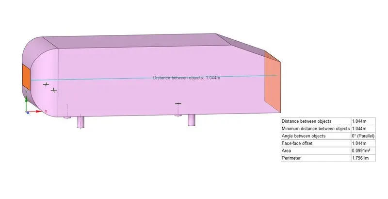
Ahmed Body dimensional properties in meters.
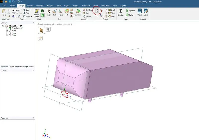
The above image guides us to create the reference planes that will aid in the split body command.
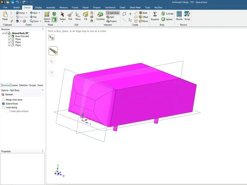
The split body command is used as shown in the the above image and XY plane is selected to split the ahmed body in exact two halves. The half to be removed has to be clicked and balance half body remains as shown in the below image.
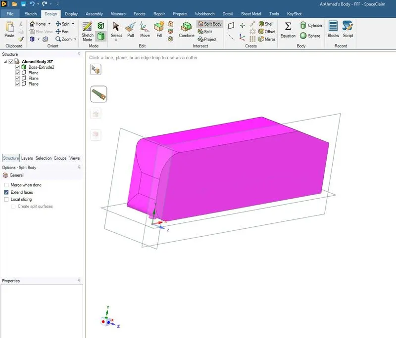
The reference planes which are visible in the above image are hidden by unclicking the ticks in the Structure tree.
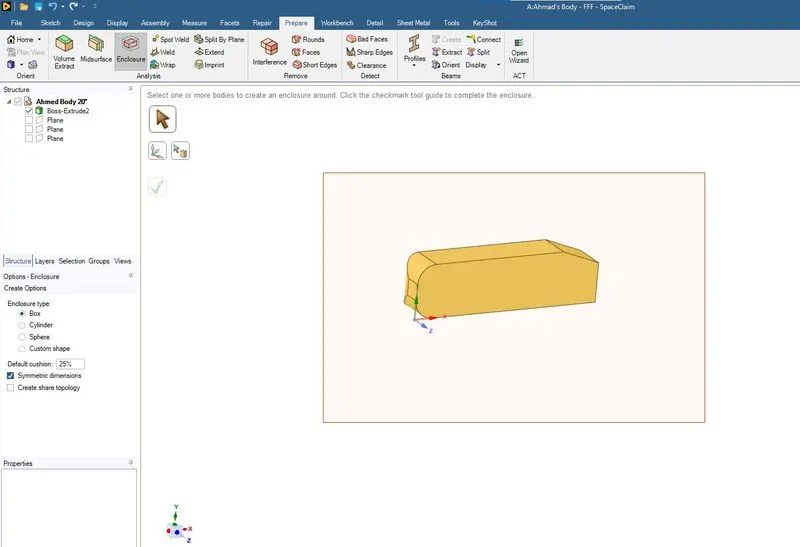
Now the enclosure is created using the Enclosure command in Prepare tab. Select enclosure and create a selection box by draging the mouse as shown in the above image.
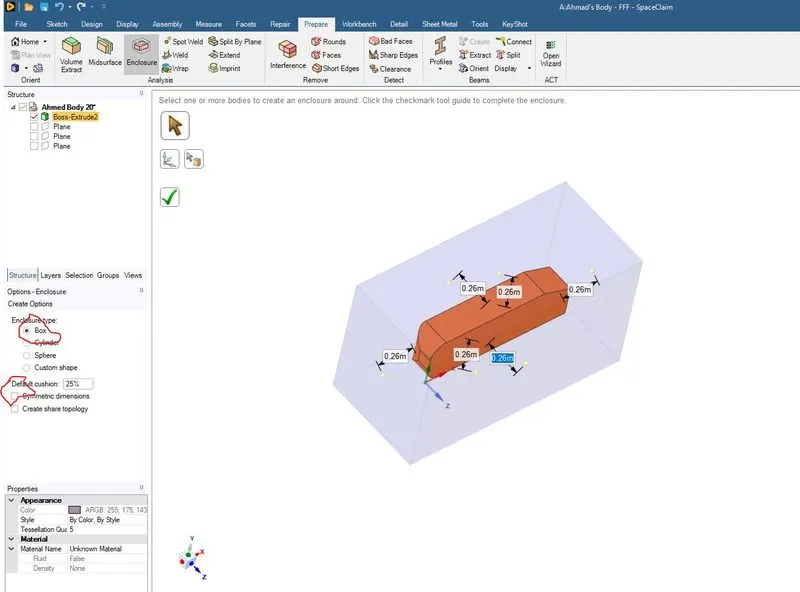
The enclosure type is selected as shown in the red encirled and unticking the Symmetric dimensions.
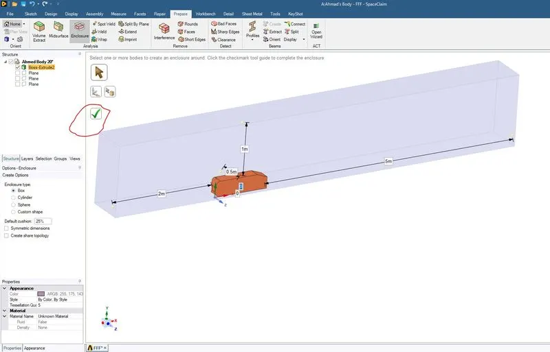
The dimensions of the enclosure are as shown in the image.
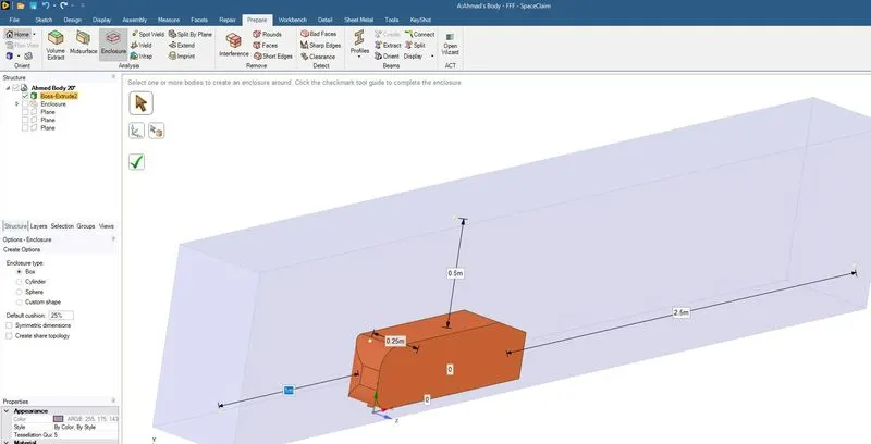
The inner emclosure is created to capture the flow by generating refine mesh near ahmed body and reducing the overall mesh elements. The dimensions are as shown in the above image.
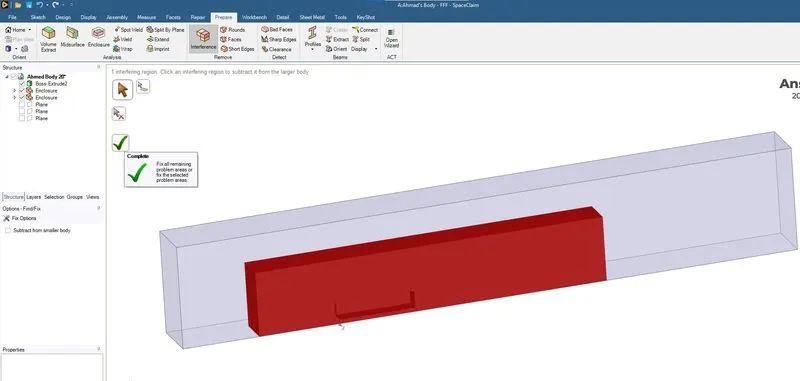
Interference option is used to find the interfering and subtract it from the larger body.
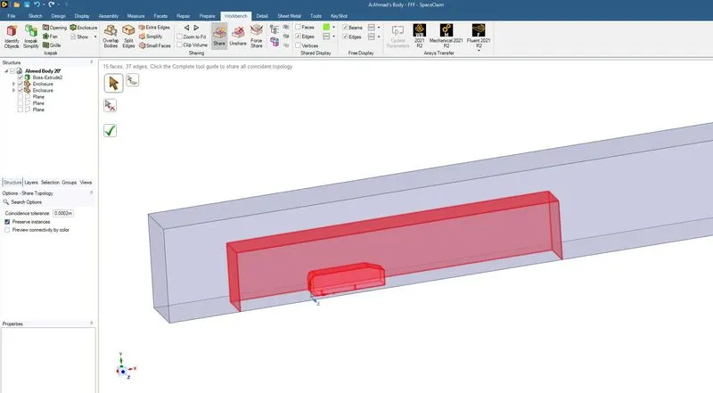
Share Topology is used as shown in the above image. This option helps to have better connectivity of meshing elements near the common edges or faces in the enclosures and Ahmed body.
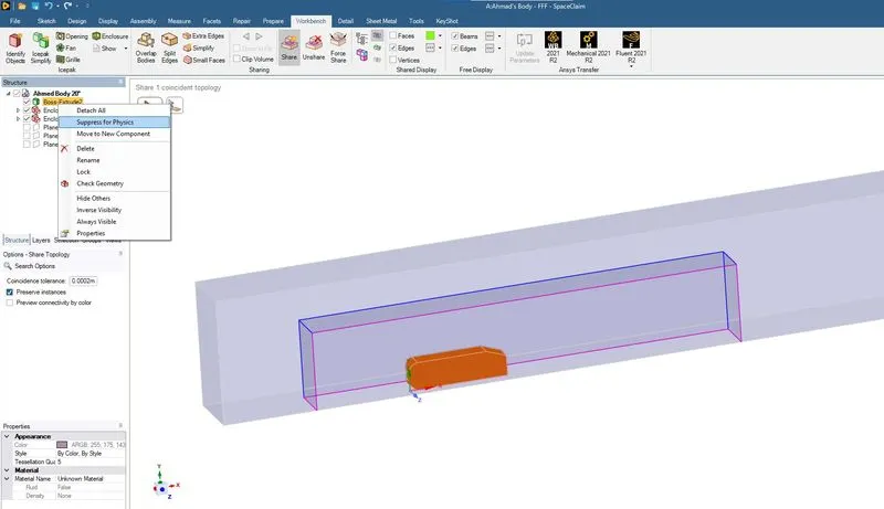
Suppres the Ahmed body for physics as shown in the image. This step is done as we are interested in the external flow over the Ahmed body and the concerned areas are the Ahmed body wall.
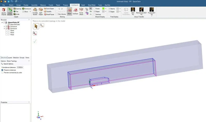
In this step we delete the reference planes as they are no longer required for further processing.
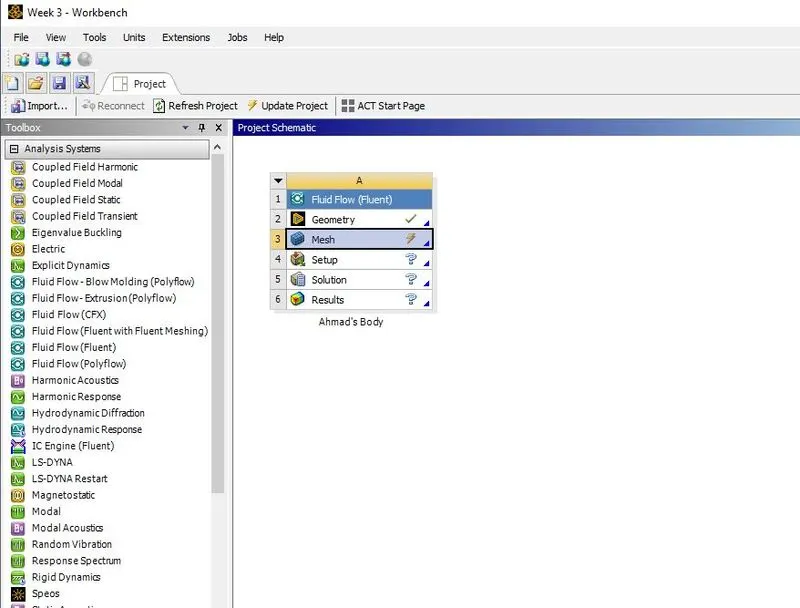
The Mesh is clicked to start the meshing module as shown in the above image.
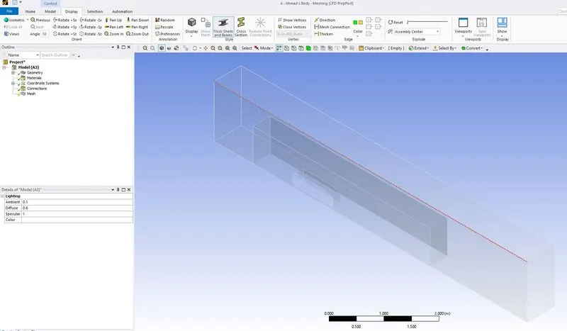
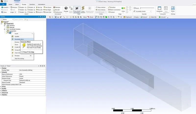
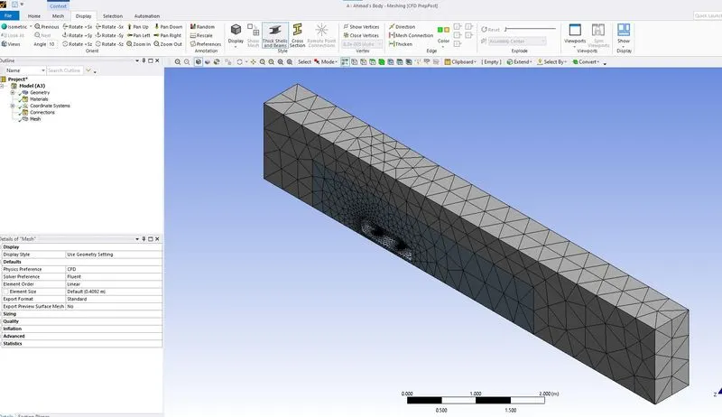
The default mesh is generated as shown in the above images.
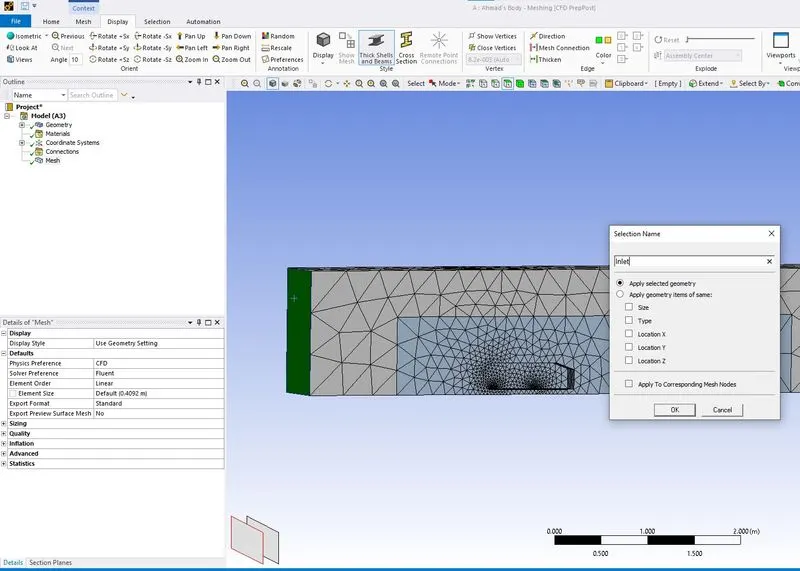
Using Named Selection, the selected face is named as Inlet.
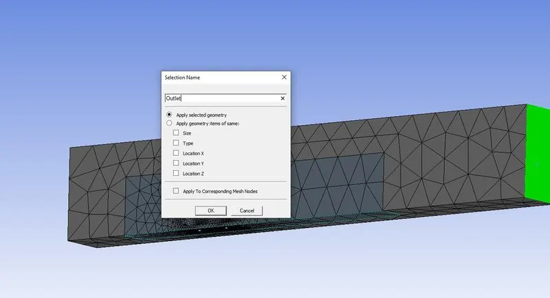
Using Named Selection, the selected face is named as Outlet. Similarly the remaining face of the enclosure is named as Symmetry. Now using the hide faces some faces of the enclosure are hidden and using box select the ahmed body faces are selected and it is named as Ahmed Body Wall.
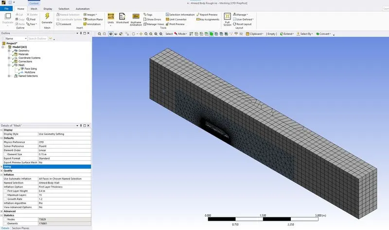
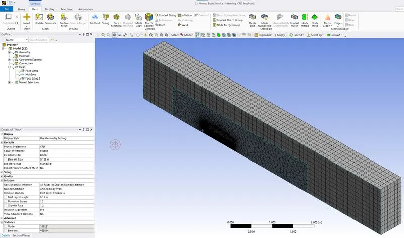
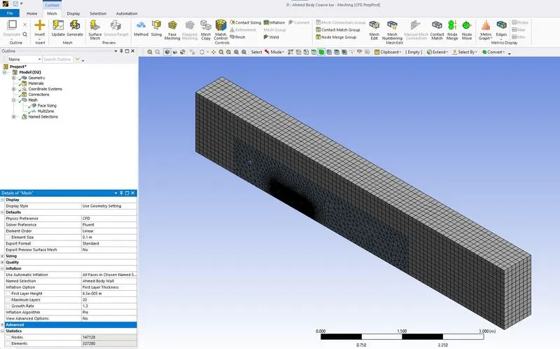
THe above mesh element were generated by using face sizing for ahmed body wall and multizone method for outer enclosure. Final rough mesh elements before entering the fluent setup.
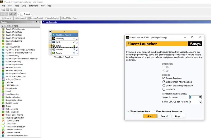
Fluent set up is started as shown in the above image.
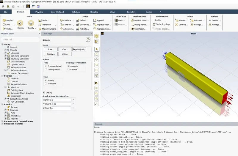
Gravity is enabled as shown in the above image.
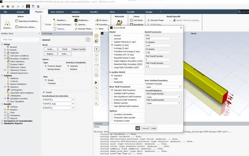
K-epsilon method is selected in viscous model under physics tab as shown in the above image.
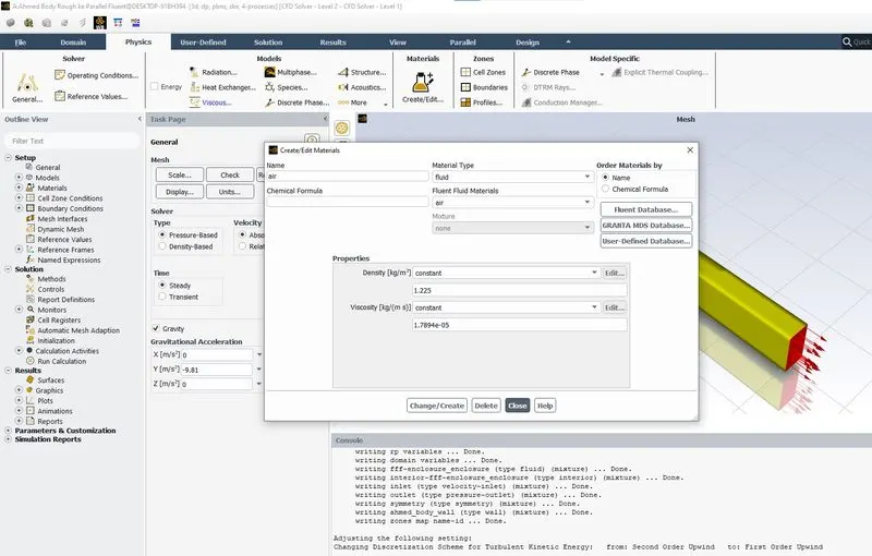
Selected air as the fluid material as shown in the above image.
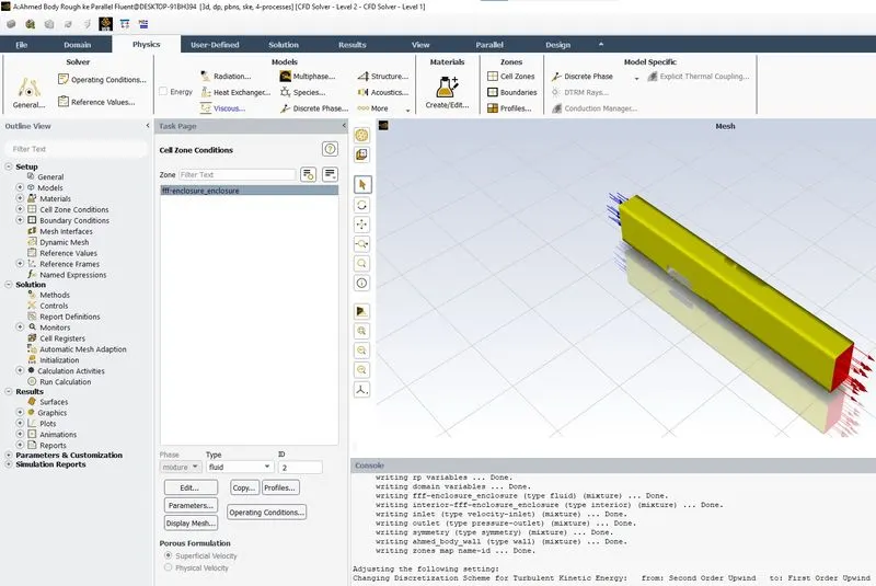
Under the cell zone conditions selected the type as fluid for enclosures as shown in the above image.
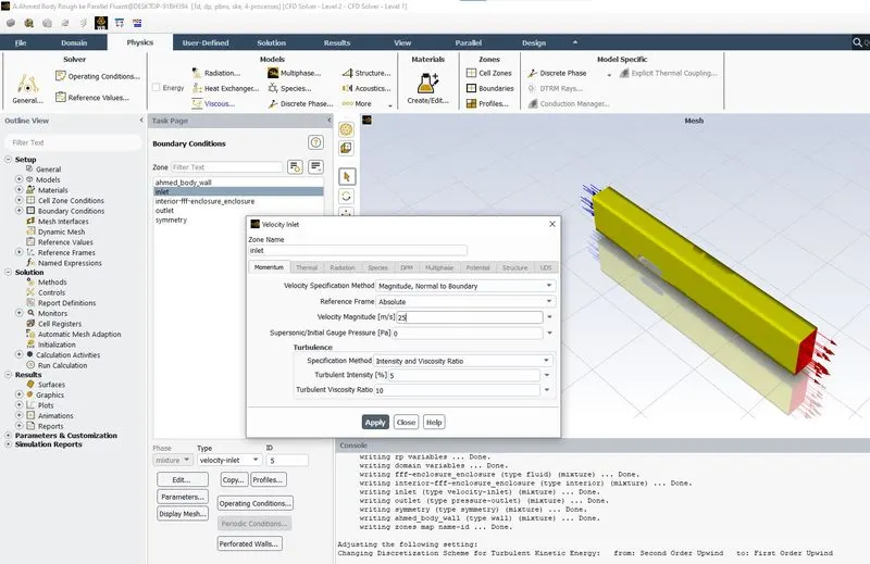
Inlet boundary conditons of inlet velocity 25m/s is set as shown in the above image.
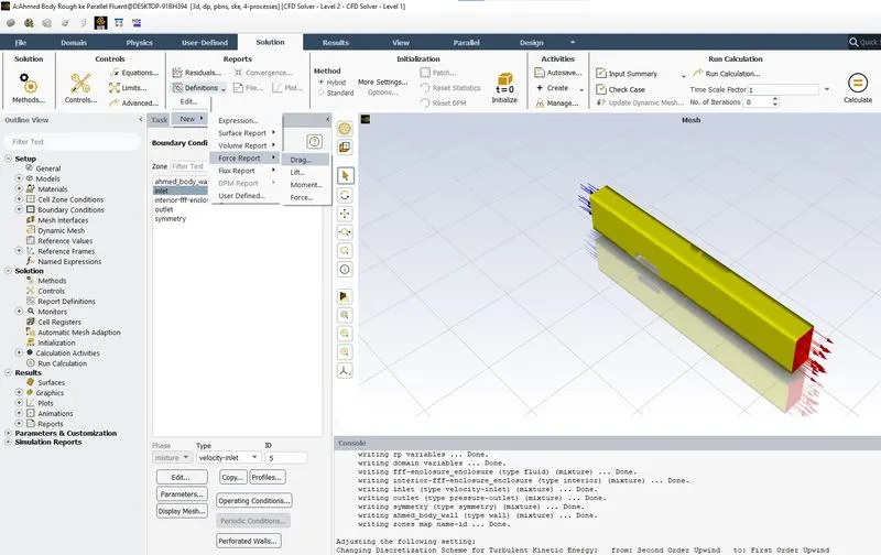
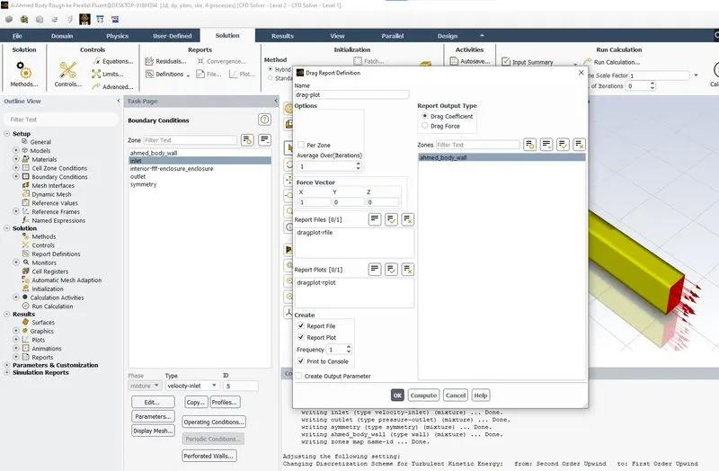
Drag plot definitions is set as shown in the above image.
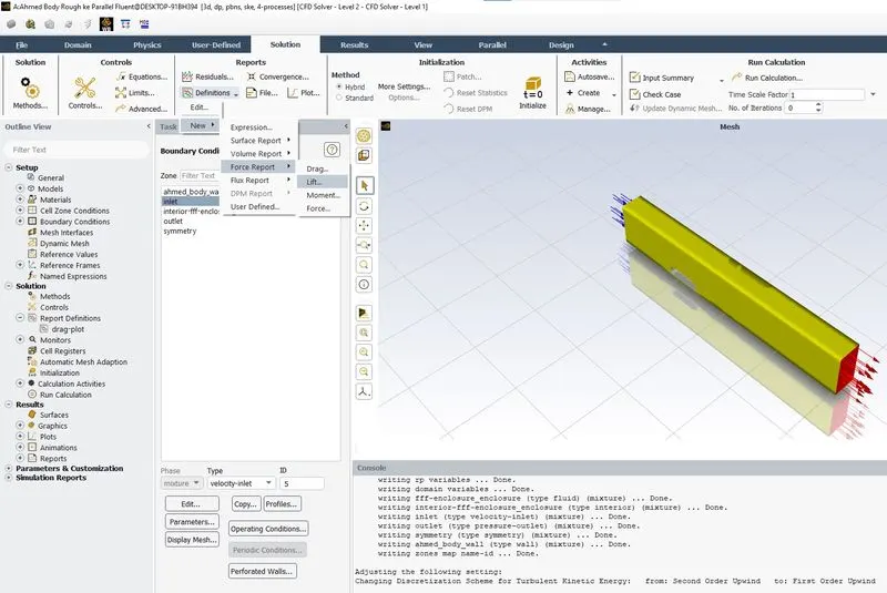
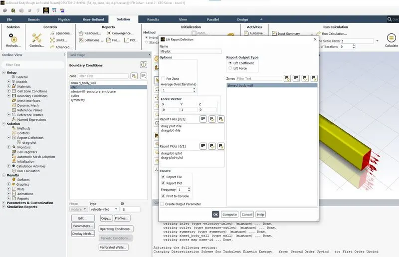
Lift plot definitions is set as shown in the above image.
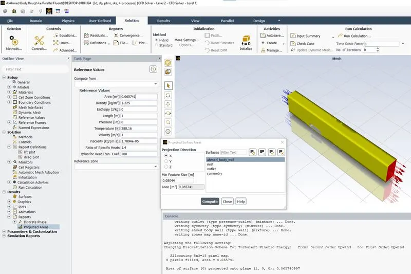
Projected area is computed as shown in the above image.
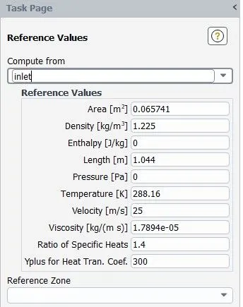
The final reference values are set as shown in the above image.
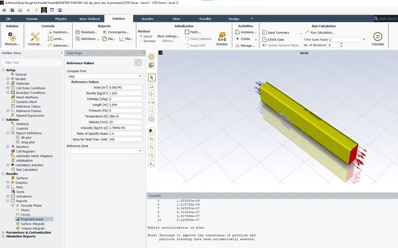
Hybrid initialization is done as shown in the above image.
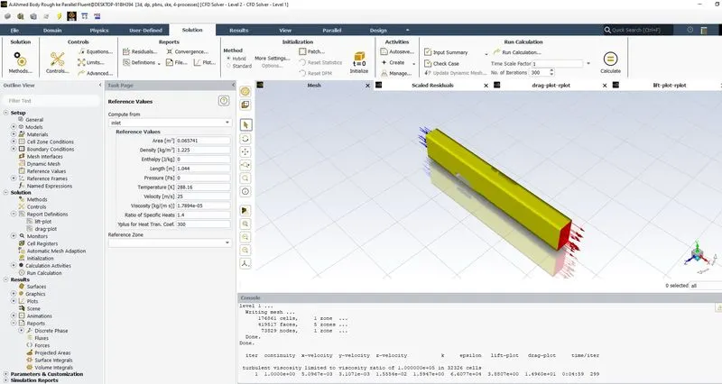
Calculation is run by setting the number of iteration as 300 as shown in the above image.
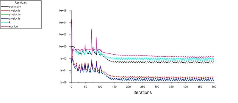
After the solution is converged we get the drag plot, lift Plot and scaled residuals.
The following cases done using ANSYS fluent (Refer the below image)
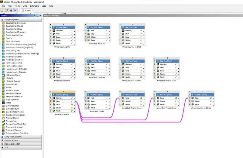
1.Ahmed Body Rough ke 25mps
1.1 Mesh Elements
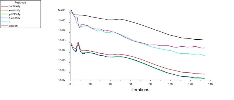
1.2 Scaled Residuals
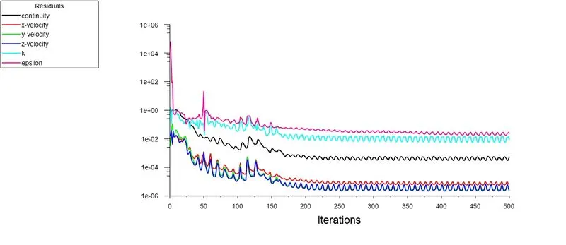
1.3 Drag Plot
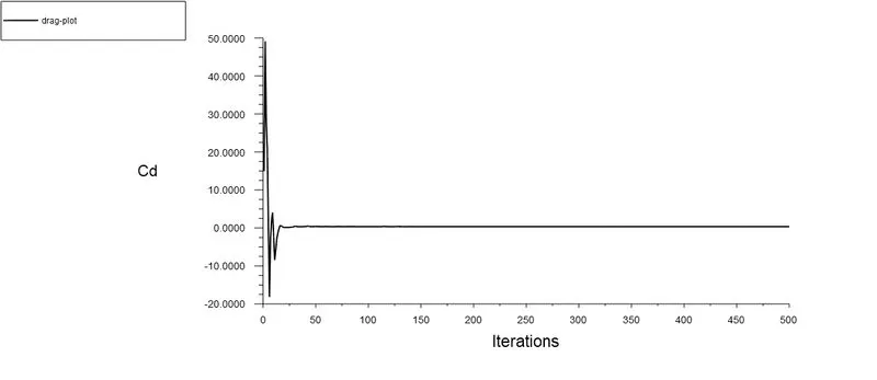
1.4 Lift Plot
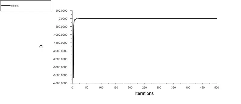
1.5 Drag Coeffeicient
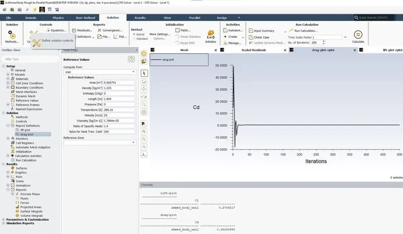
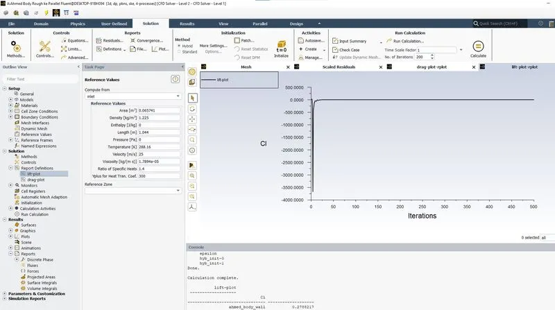
1.6 Lift Coefficient
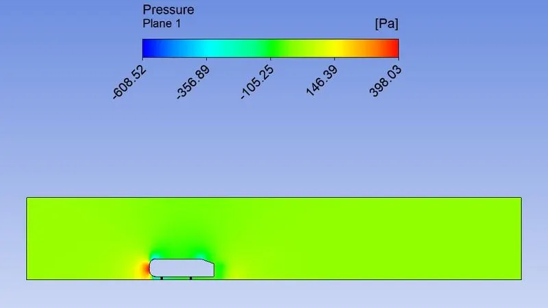
1.7 Pressure Contour
1.8 Velocity Contour
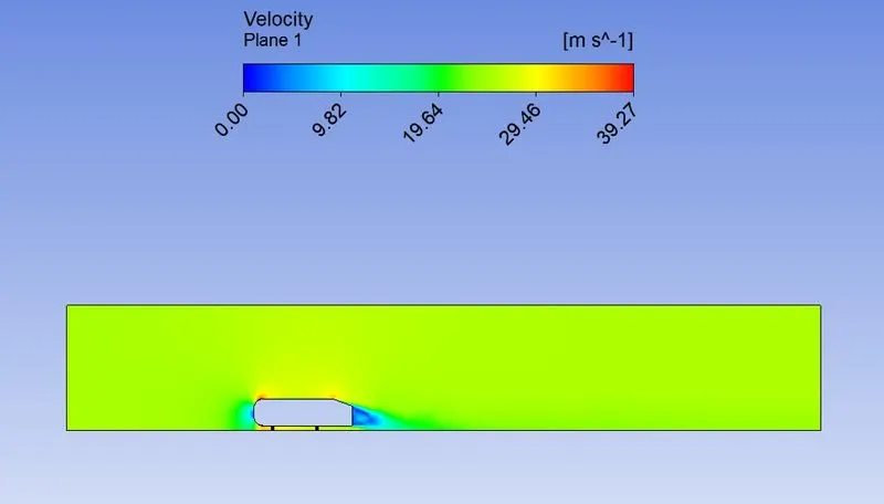
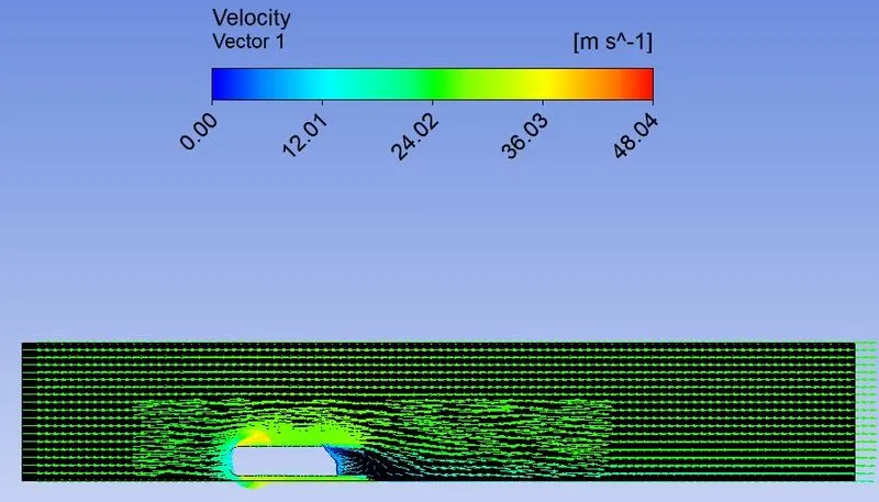
1.9 Velocity Vector Plot
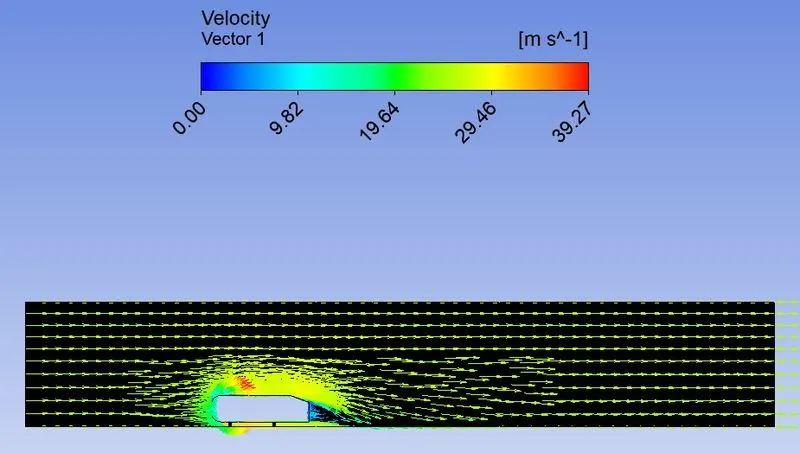
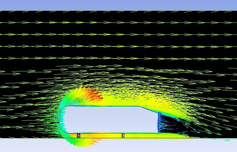
2.Ahmed Body Coarse ke 25mps
2.1 Mesh Elements
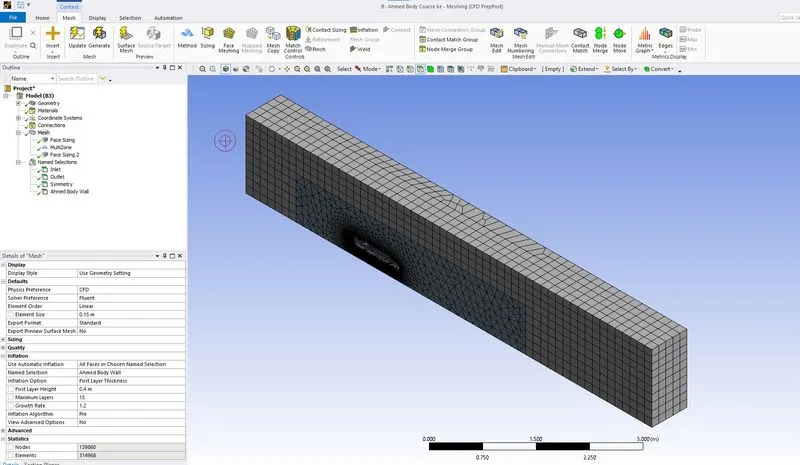
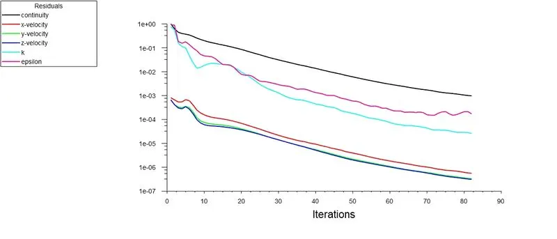
2.2 Scaled Residuals
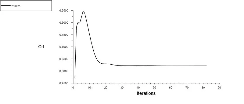
2.3 Drag Plot
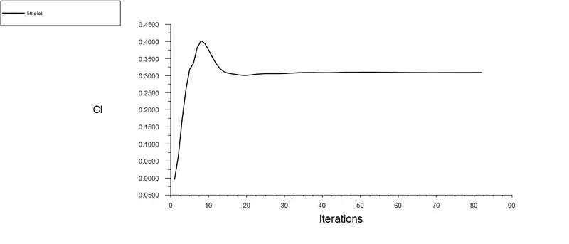
2.4 Lift Plot
2.5 Drag Coeffiient
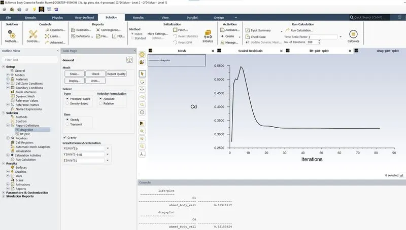
2.6 Lift Coefficient
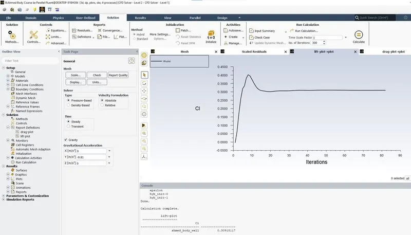
2.7 Pressure Contour
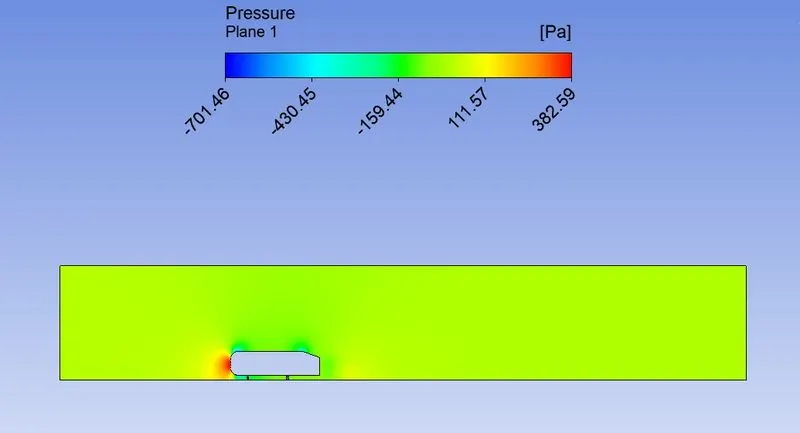
2.8 Velocity Contour
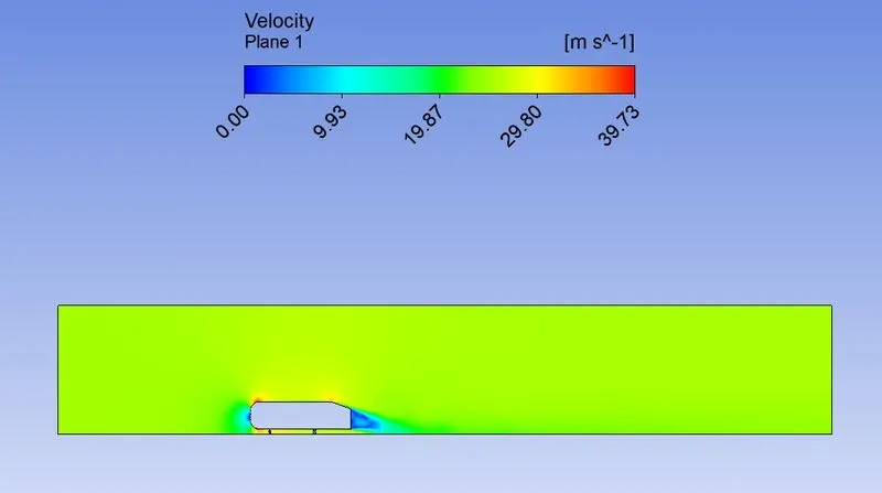
2.9 Velocity Vector Plot
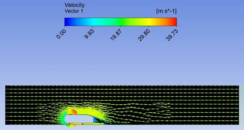
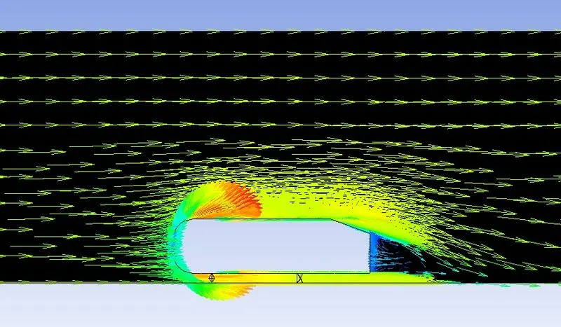
3.Ahmed Body Fine ke 25mps
3.1 Mesh Elements
3.2 Scaled Residuals
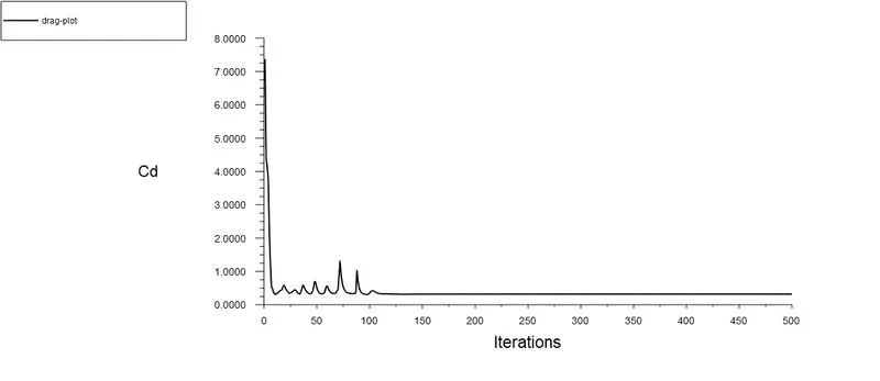
3.3 Drag Plot
3.4 Lift Plot
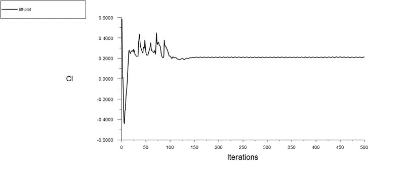
3.5 Drag Coefficient
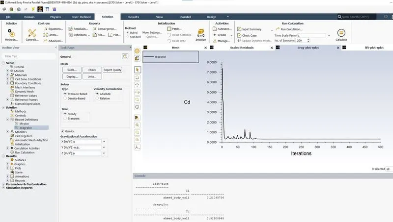
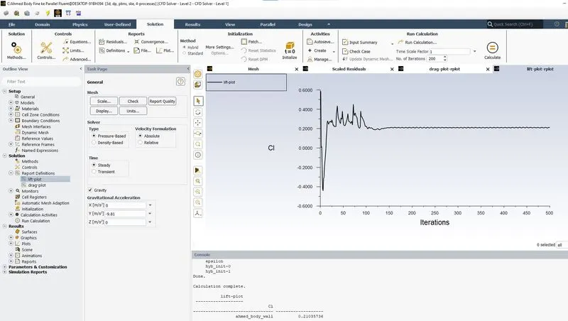
3.6 Lift Coefficient
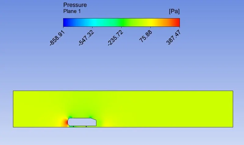
3.7 Pressure Contour
3.8 Velocity Contour
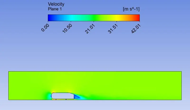
3.9 Velocity Vector Plot
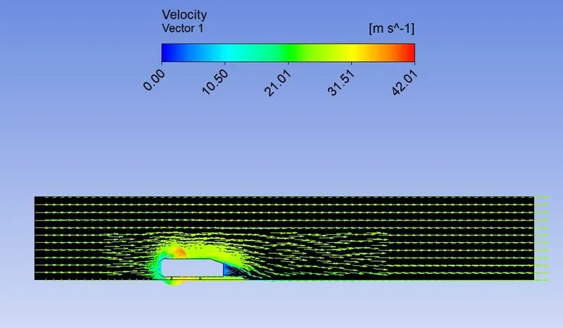
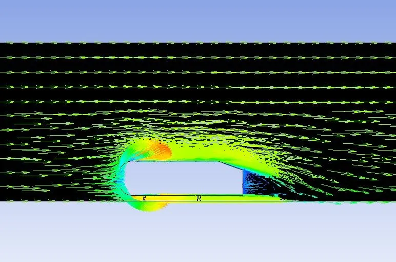
4.Ahmed Body Rough kw 25mps
4.1 Mesh Elements
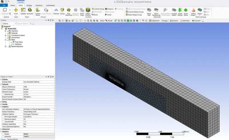
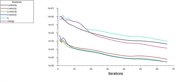
4.2 Scaled Residuals
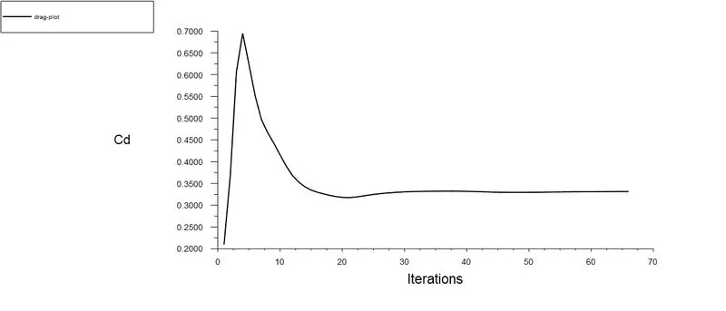
4.3 Drag Plot
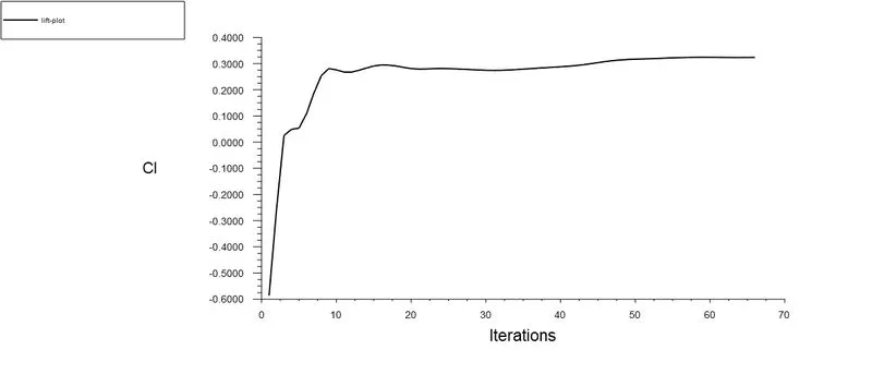
4.4 Lift Plot
4.5 Drag Coefficient
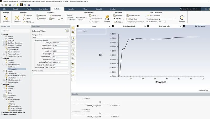
4.6 Lift Coefficient
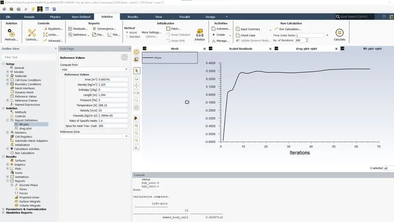
4.7 Pressure Contour
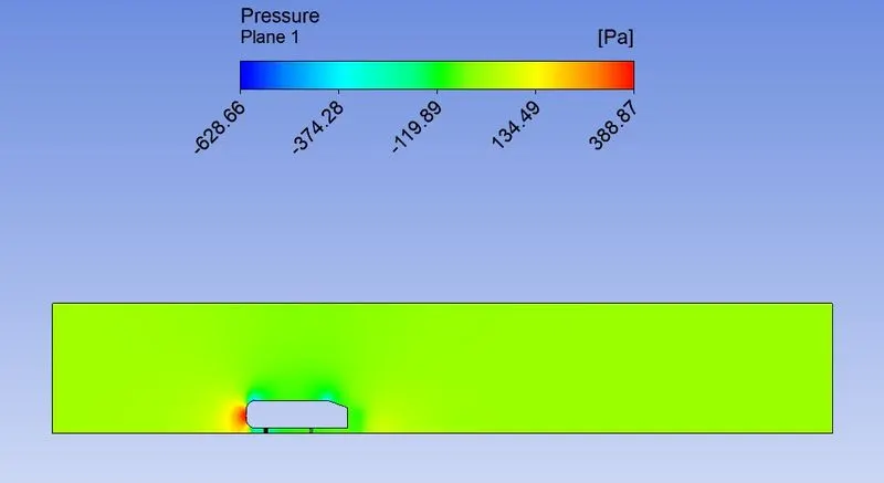
4.8 Velocity Contour
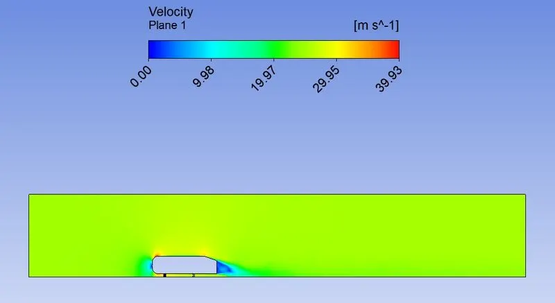
4.9 Velocity Vector Plot
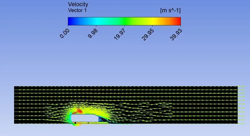
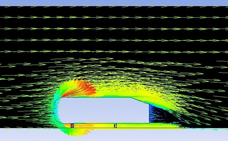
5.Ahmed Body Coarse kw 25mps
5.1 Mesh Elements
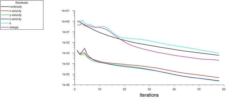
5.2 Scaled Residuals
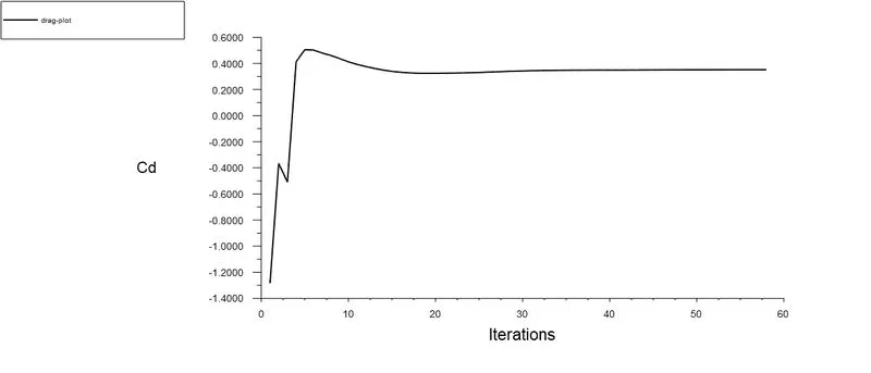
5.3 Drag Plot
5.4 Lift Plot
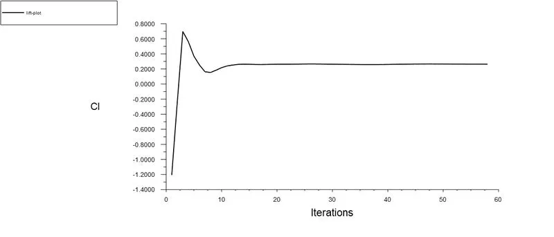
5.5 Drag Coefficient
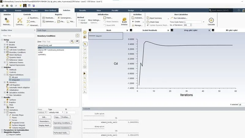
5.6 Lift Coefficient
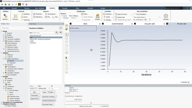
5.7 Pressure Contour
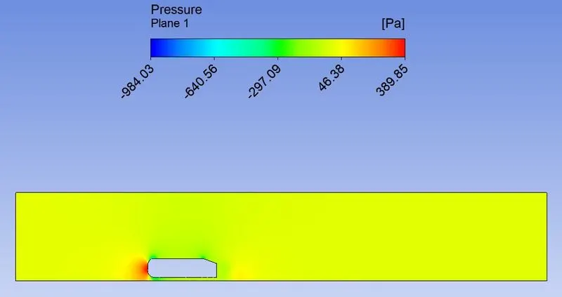
5.8 Velocity Contour
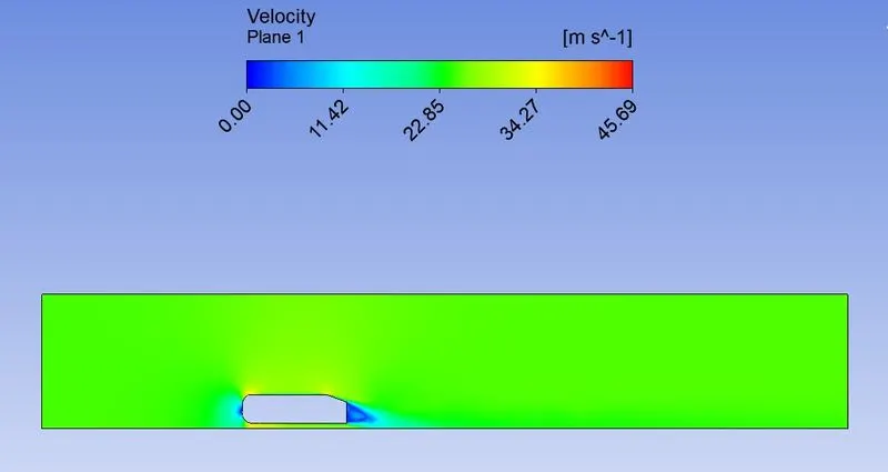
5.9 Velocity Vector Plot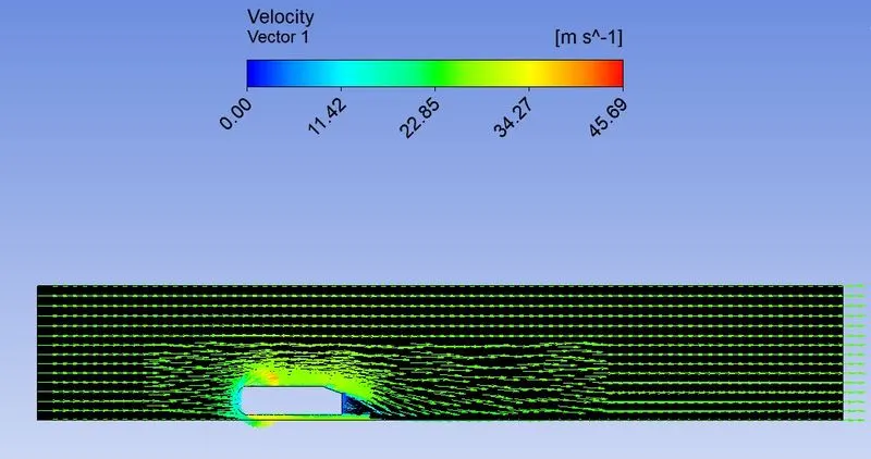
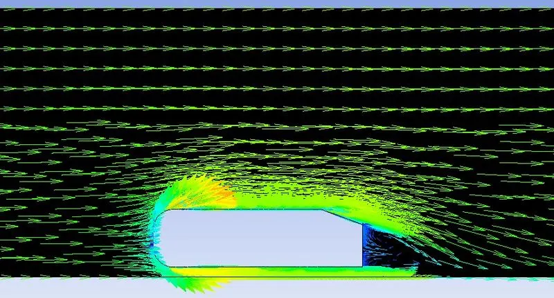
6.Ahmed Body Fine kw 25mps
6.1 Mesh Elements
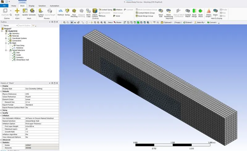
6.2 Scaled Residuals
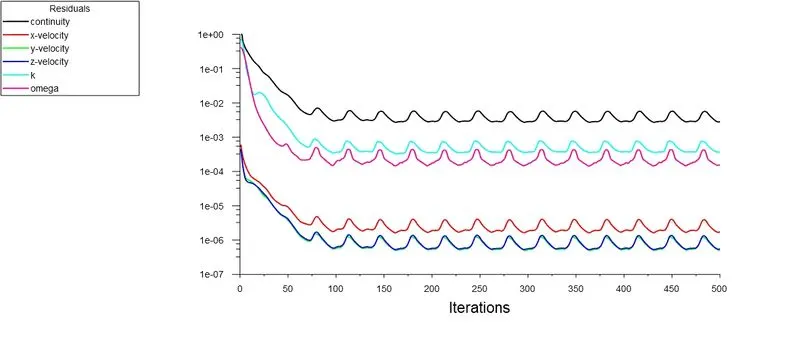
6.3 Drag Plot
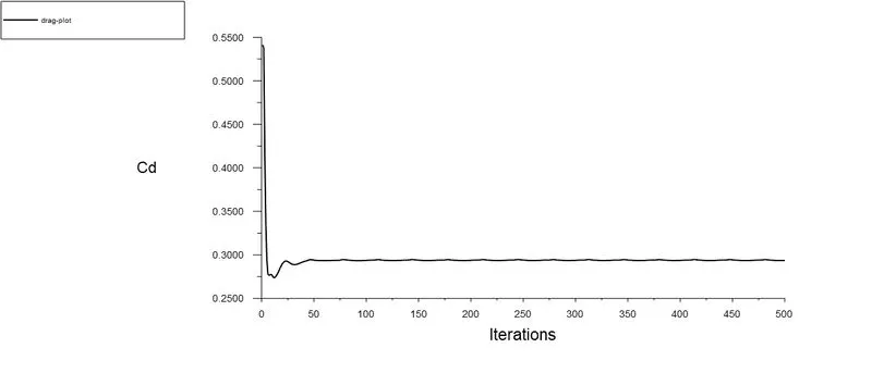
6.4 Lift Plot
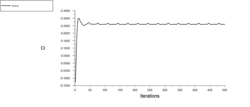
6.5 Drag Coefficient
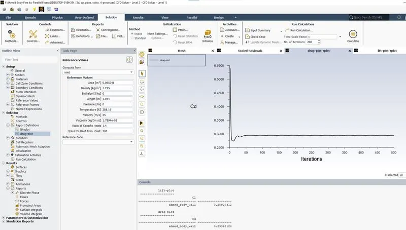
6.6 Lift Coefficient
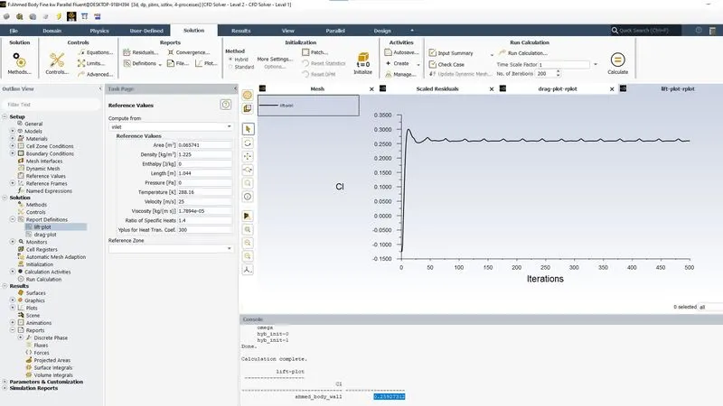
6.7 Pressure Contour
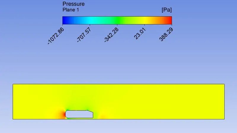
6.8 Velocity Contour
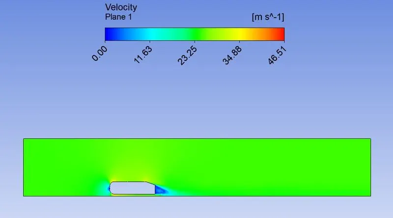
6.9 Velocity Vector Plot
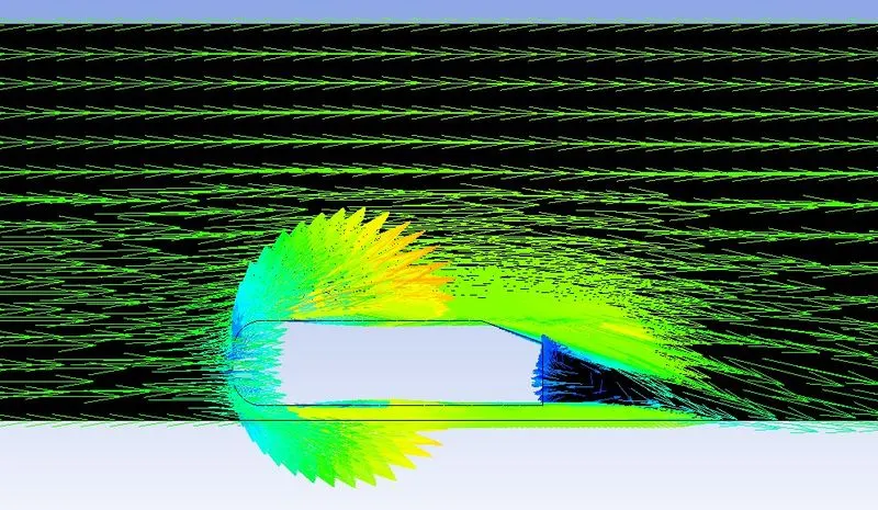
7.Ahmed Body Fine ke 40mps
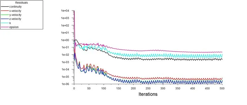
7.1 Scaled Residuals
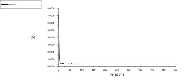
7.2 Drag Plot
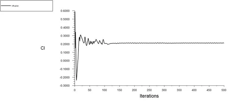
7.3 Lift Plot
7.4 Drag & Lift Coefficient
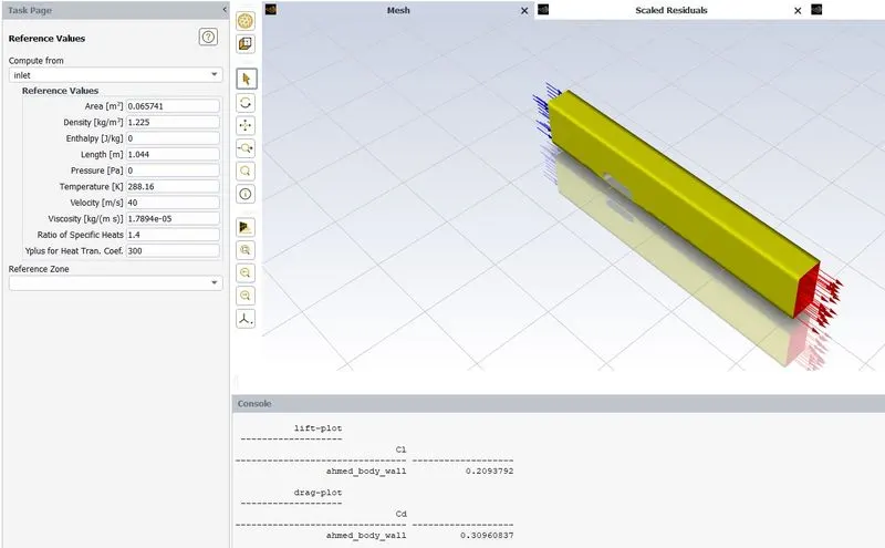
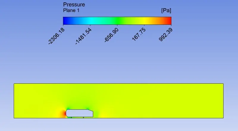
7.5 Pressure Contour
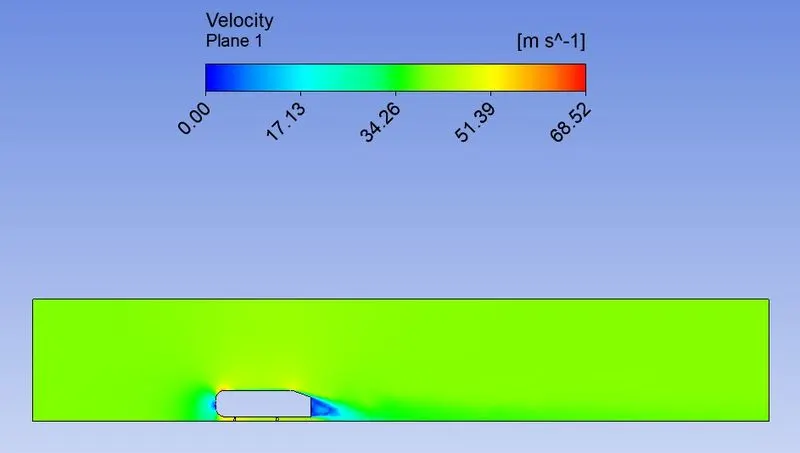
7.6 Velocity Contour
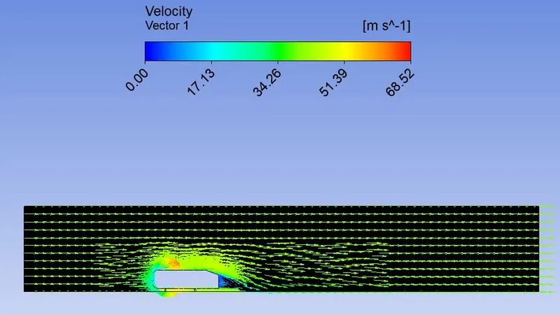
7.7 Velocity Vector Plot
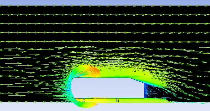
8.Ahmed Body Fine ke 60mps
8.1 Scaled Residuals
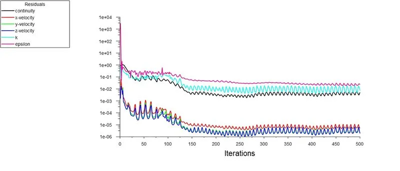
8.2 Drag Plot
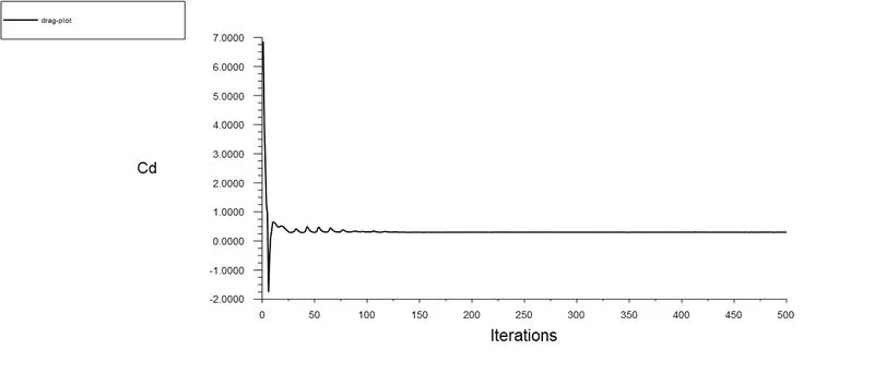
8.3 Lift Plot
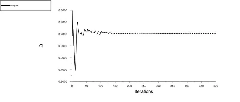
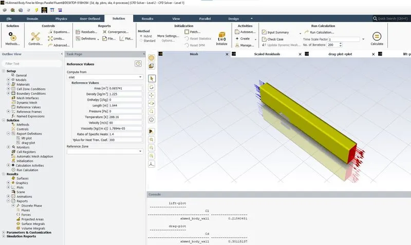
8.4 Drag & Lift Coefficients
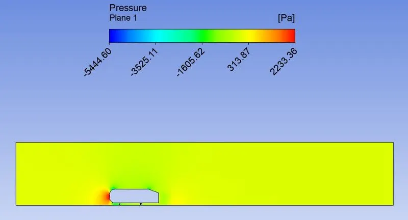
8.5 Pressure Contour
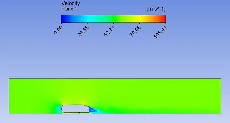
8.6 Velocity Contour
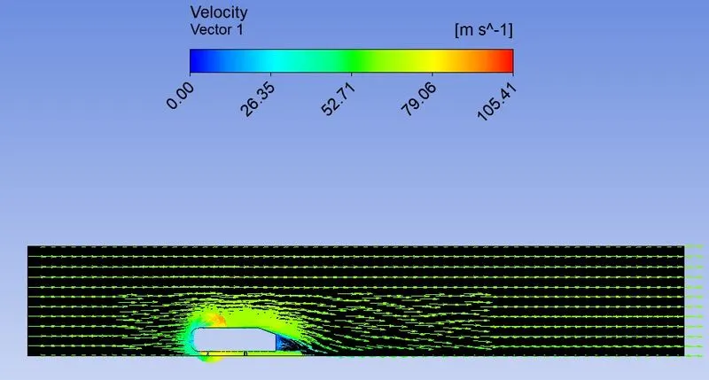
8.7 Velocity Vector Plot
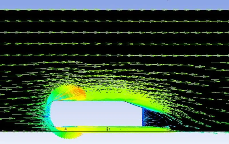
9.Ahmed Body Fine ke 85mps
9.1 Scaled Residuals
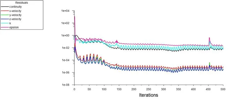
9.2 Drag Plot
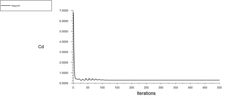
9.3 Lift Plot
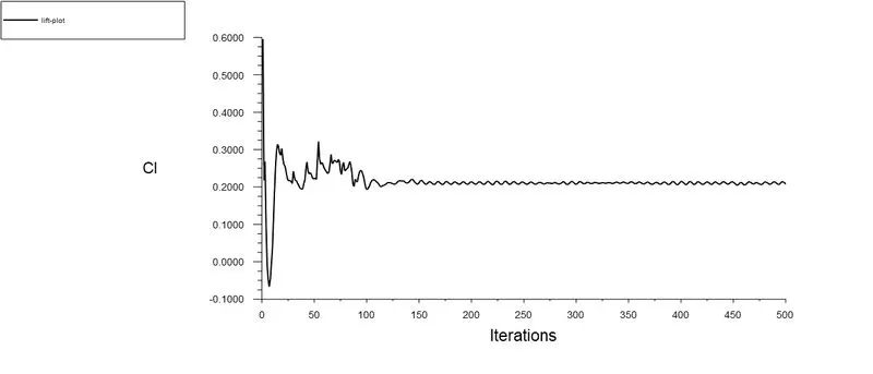
9.4 Drag & Lift Coefficients
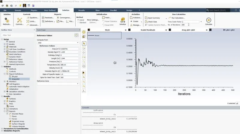
9.5 Pressure Contour
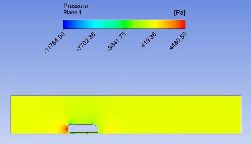
9.6 Velocity Contour
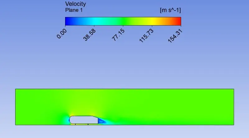
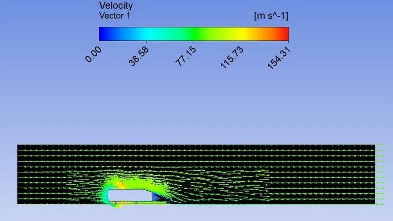
9.7 Velocity Vector Plot
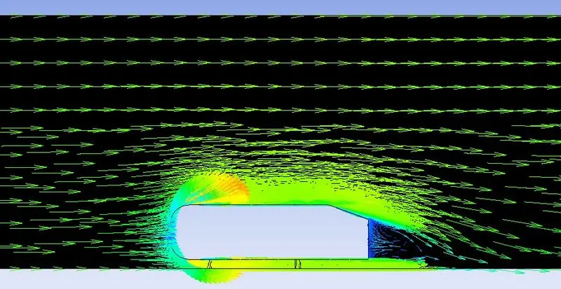
10.Ahmed Body Fine ke 25mps Slant Angle 30deg
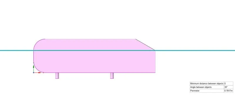
10.1 Geometry
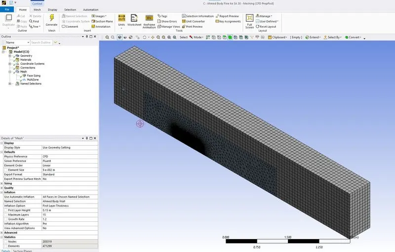
10.2 Mesh Elements
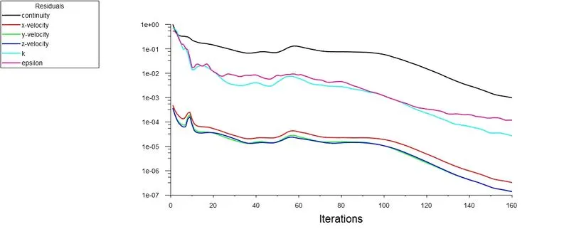
10.3 Scaled Residuals
10.4 Drag Plot
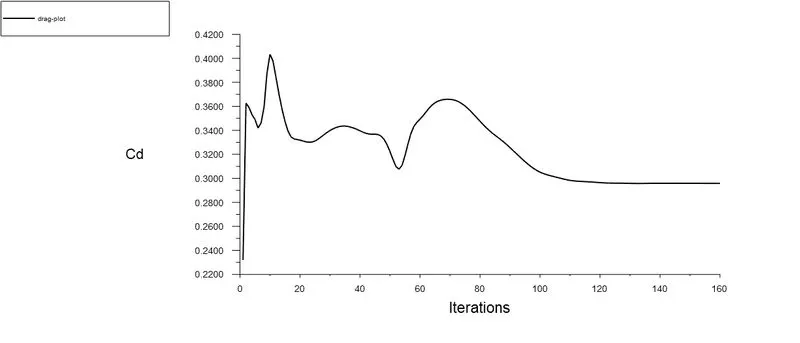
10.5 Lift Plot
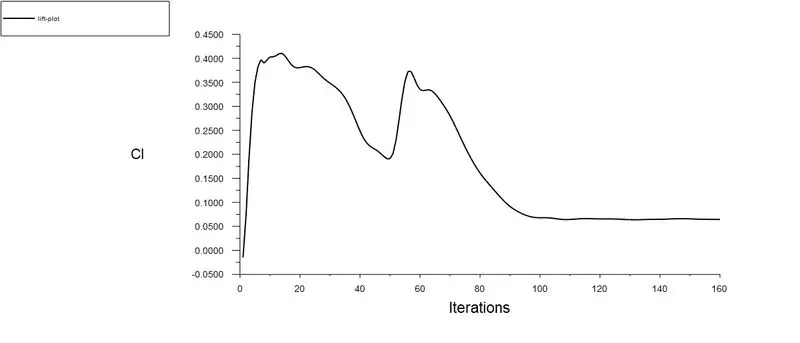
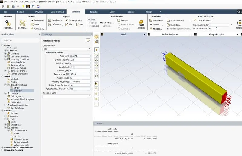
10.6 Drag & Lift Coefficient
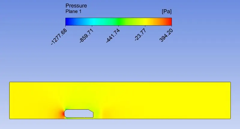
10.7 Pressure Contour
10.8 Velocity Contour

10.9 Velocity Vector Plot
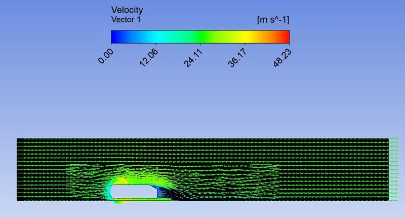
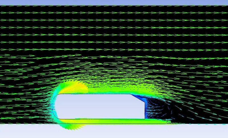
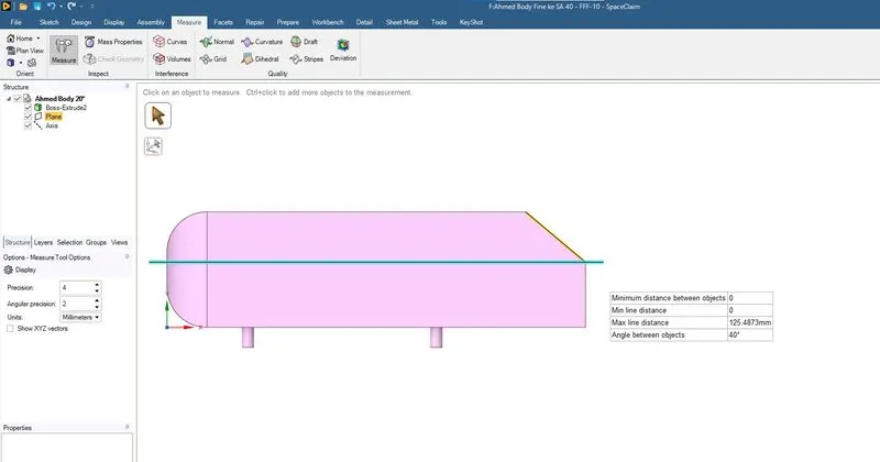
11.Ahmed Body Fine ke 25mps Slant Angle 40deg
11.1 Geometry
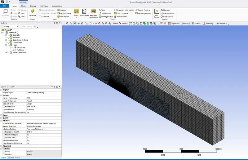
11.2 Mesh Elements
11.3 Scaled Residuals
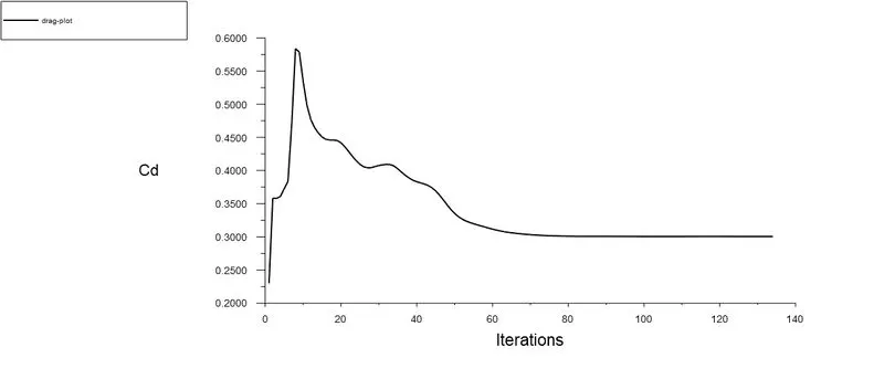
11.4 Drag Plot
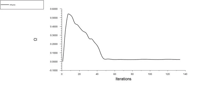
11.5 Lift Plot
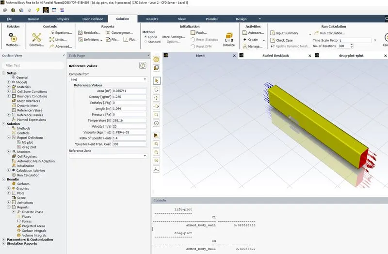
11.6 Drag & Lift Coefficient
11.7 Pressure Contour
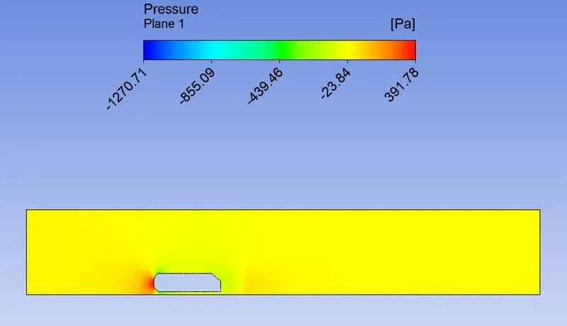
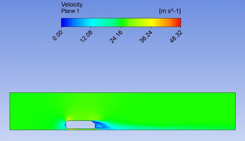
11.8 Velocity Contour
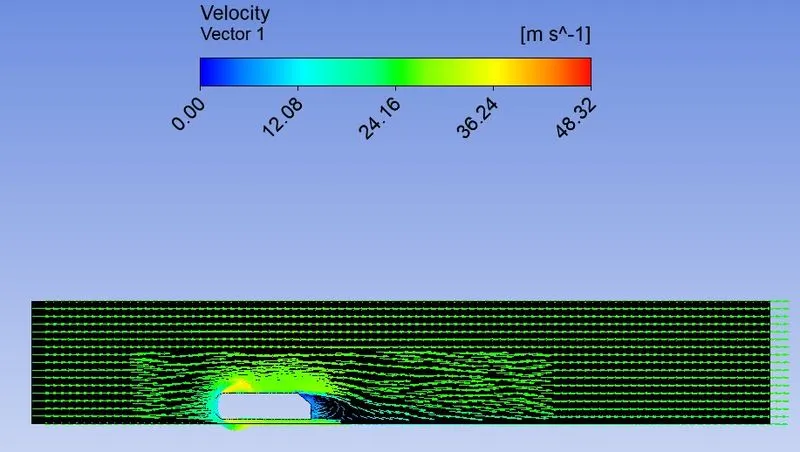
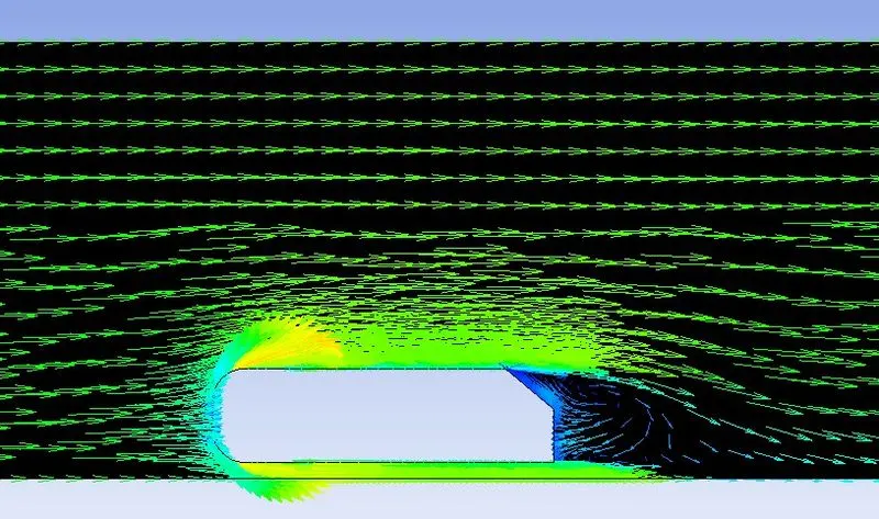
11.9 Velocity Vector Plot
12.Ahmed Body Fine ke 25mps Slant Angle 50deg
12.1 Geometry
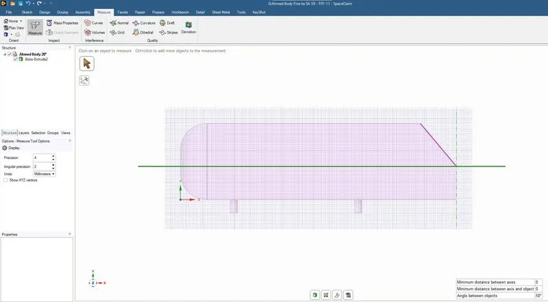
12.2 Mesh Elements
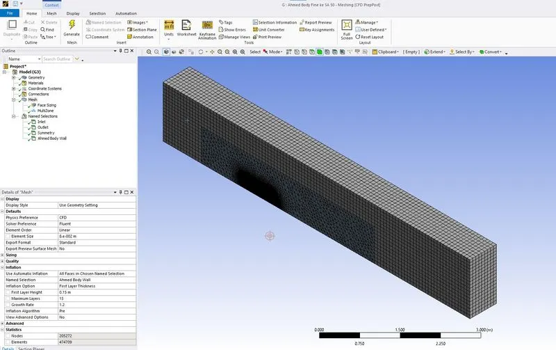
12.3 Scaled Residuals
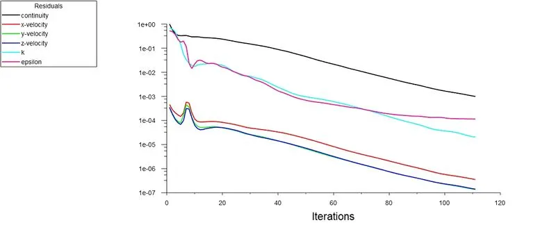
12.4 Drag Plot
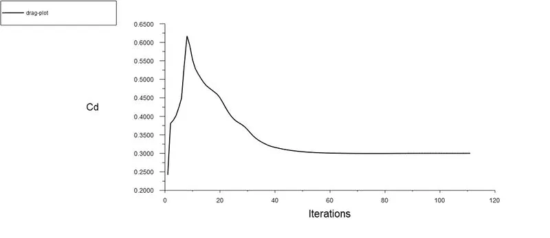
12.5 Lift Plot
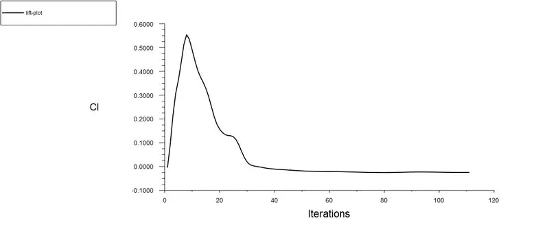
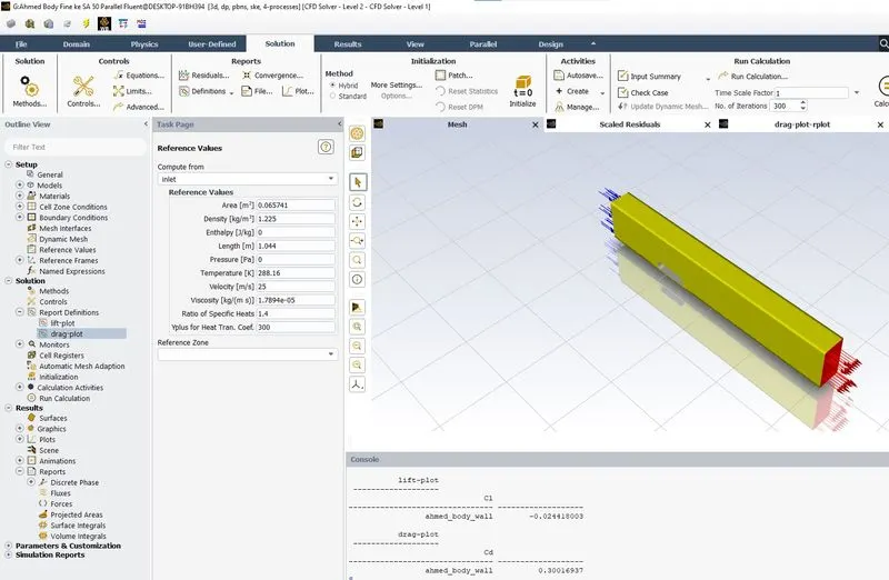
12.6 Drag & Lift Coefficient
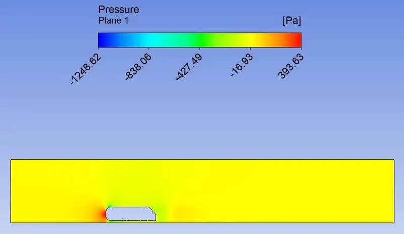
12.7 Pressure Contour
12.8 Velocity Contour
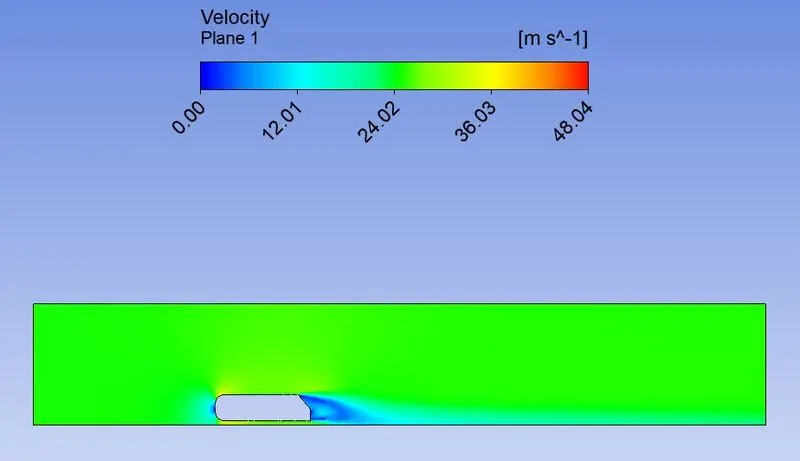
12.9 Velocity Vector Plot
SUMMARY


CONCLUSION
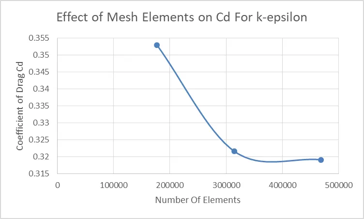
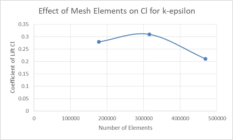
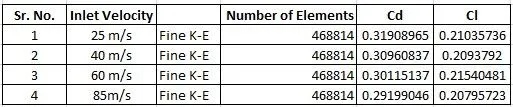
1) K-epsilon Model Fine Mesh, Coefficient of Drag & Lift reduces. The Coefficient of Drag obtained is 0.31908965 & Coefficient of Lift is 0.21035736
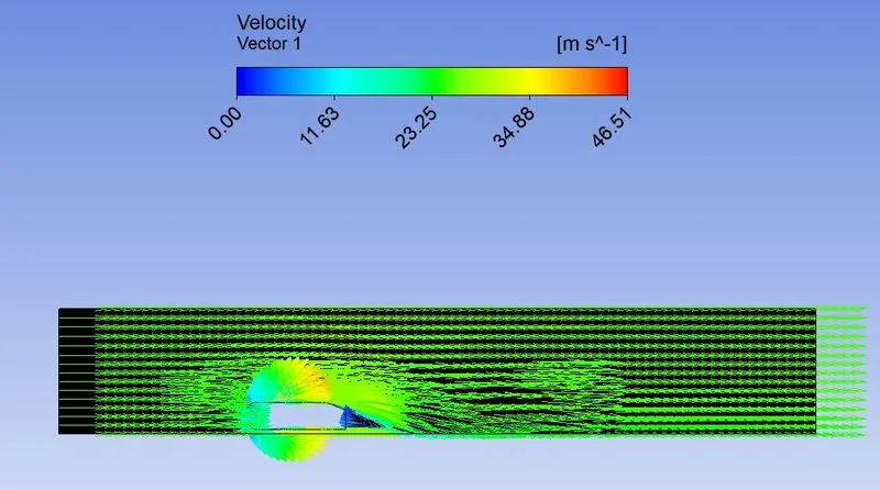
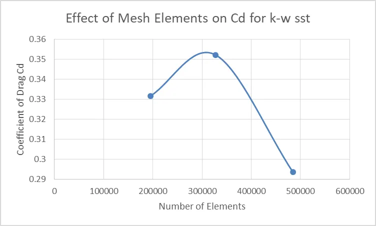
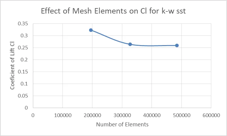
2) K-W SST Model Fine Mesh, The Coefficient of Drag obtained is 0.29362124 & Coefficient of Lift is 0.25927312
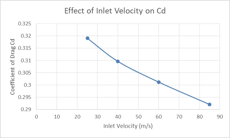
3) Coefficient of drag reduces with the increase in inlet velocity.
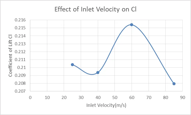
4) Coeficient of lift has periodic variation with an increase in inlet velocity.
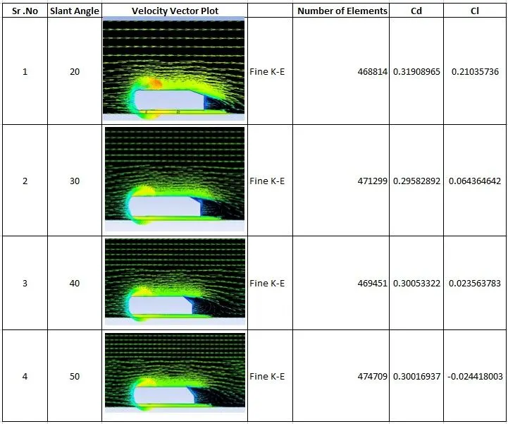
5) Effect of increase in Slant Angle, the flow separation starts early with an increase in slant angle at the trailing portion in the ahmed body. Wage region shits near the slope from vertical boundary with an increase in slant angle