Week 3 - External flow simulation over an Ahmed body.
Aim:
External flow simulation over an Ahmed body at different.
Objective:
The main objective of this challenge is to perform an flow simulation over an Ahmed body and to find out drag and lift coeficient and to perform the grid independence Test.
Expected Results:
1. Velocity and pressure contours.
2. The drag coefficient plot for a refined case. ( For a velocity of 25m/sec, the drag coefficient should be around 0.33).
3. The vector plot clearly showing the wake region.
4. Perform the grid independence test and provide the values of drag and lift with each case.
Introduction:
Ahmed body:
The Ahmed body is a generic car body (a simplified vehicle model). The airflow around the Ahmed body captures the essential flow features around an automobile and was first defined and characterized in the experimental work of Ahmed . Although it has a very simple shape, Ahmed body allows us to capture characteristic features that are relevant to bodies in the automobile industry.
This model is also used to describe the turbulent flow field around a car-like geometry. Once the numerical model in validated, it is used to design new models of the car.
Importance of Ahmed body:
- The drag force is an important factor considering fuel consumption. As the drag force increases the fuel consumption also increases which in turn becomes expensive for the car owners. As the burning of fossil fuels becomes an issue, the manufacturers are pressing for fuel-efficient cars.
- One of the main factors considering the car is fuel-efficient or not is the car's geometry.
- Complex shaped cars are very challenging to model and its difficult to quantify the aerodynamic drag computationally. The Ahmed body is a benchmark model widely used in the automotive industry for validating simulation tools.
- The Ahmed body has alike featured like a general car and is broadly utilized for authentication of new codes in the automobile industry
Negative pressure in the wake region
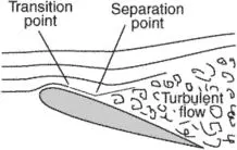
When the air moving over the vehicle is separated at the rear end, it leaves a large low-pressure turbulent region behind the vehicle which is known as the wake. This contributes to the formation of pressure drag which affects the vehicle performance.
When the vehicle is moving at a certain velocity the fluid imparts viscous force to the vehicle as long as it is in the viscous sublayer of the boundary. When the fluid reaches the rear end of the vehicle it gets detached from the surface of the body causing negative pressure in the wake region. The movement of the fluid around the vehicles depends on the geometry of the car and the Reynolds number.
Seperation Point:
let's go for challenge work
here we are going to perform grid dependence test and perform flow analysis on ahmed body.
there are stages such as
- geomentry preparation
- mesh generation
- setup and solution
- post processing
here we gonna perform basic mesh first and analyse what problems we are facing while we use normal enclosure like previous challenge
Base Mesh:
Geomentry prepartion:
open space claim and import the geomentry
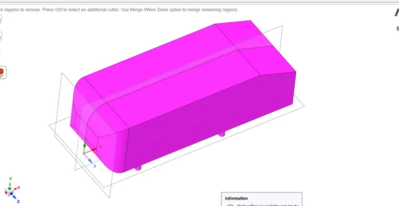
go to split body command to split the ahmed bosy ,since it is symmentrical we can also use it to make our device work with small mesh sizes.
click on split body and select geomentry and select exact mid plane
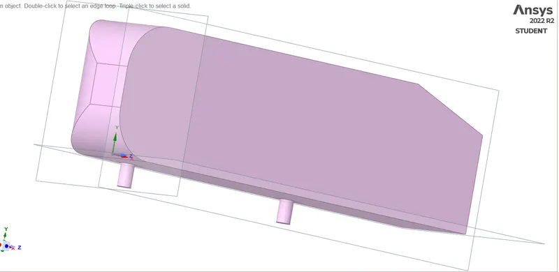
suppress the one side of ahmed bodyq
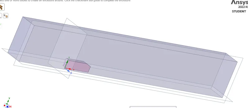
click on enclosure command and click body as shown
give dimensions as shown in sketch and click green tick and close space claim
with front distance of 2m and rear distance of 6m and side ways 0.5m and top face with distance of 1m
open mesh and generate mesh
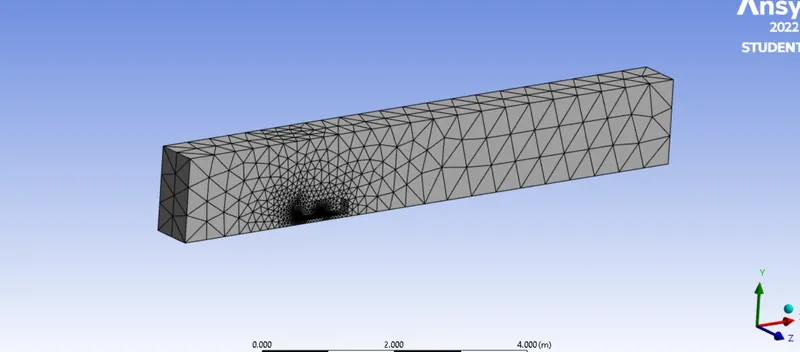
when we closely observe the mesh it is considering every thing than the body as same body.
open setup and run fluent
give inlet velocity as 25m/s
initialize the solution and create contour at cut plane with velocity variation.
also create reports for lift coefficient and drag coefficient
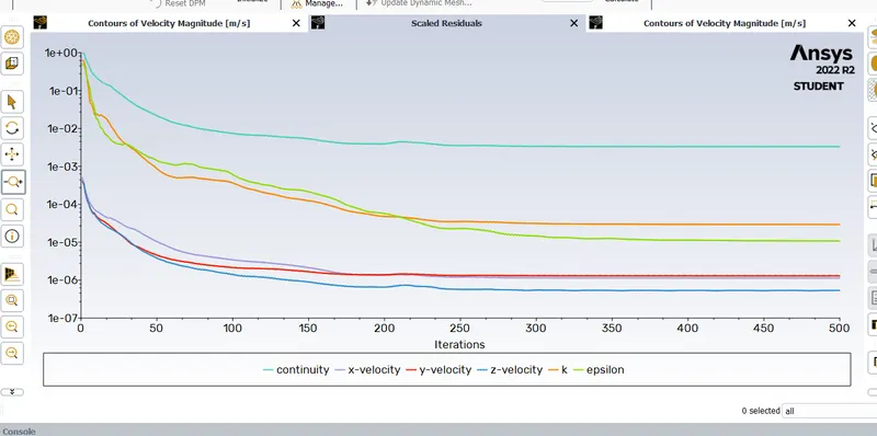
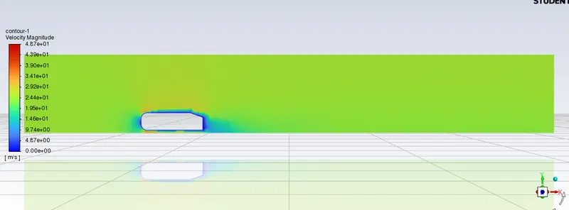
here we can see that there is no possible simulation such that only some layers possess force or drag and also negative pr behind the body is also not ok or clearly visible
then run the solution for 500 iterations
Also go to cfd post and create vector plots
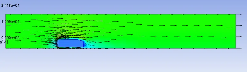
by vector plot we can also clearly see that only few force vectors are acting on body it is not good or it is not normal.
hence we need to specify another local enclosure above the body but with in created enclosure
it will specify that there is change in mesh length near body which interms provide good results lets look forward to it.
Case study:
here we are gonna perform mesh for same splited geomentry for three different mesh sizes which we can observe differnce too
Geomentry preparation:
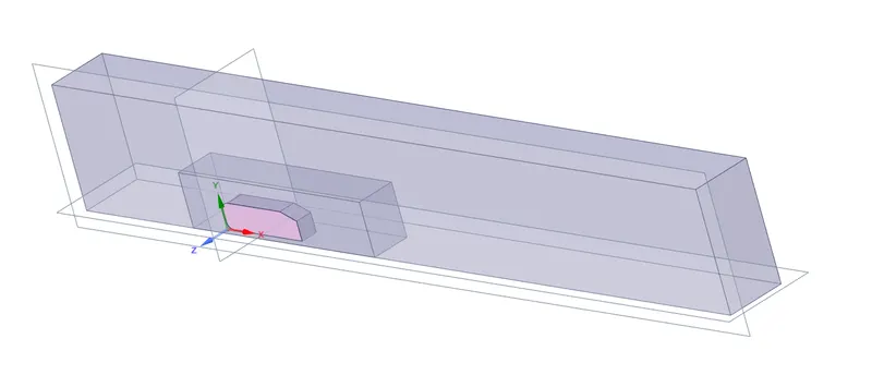
we need to create two enclosures over and over as shown in figure we also need to perform interfernce check to avoid mix up of body in two body as well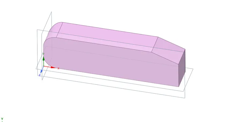
open mesh and name the selection such as inlet , outlet , car wall and symmentry as well
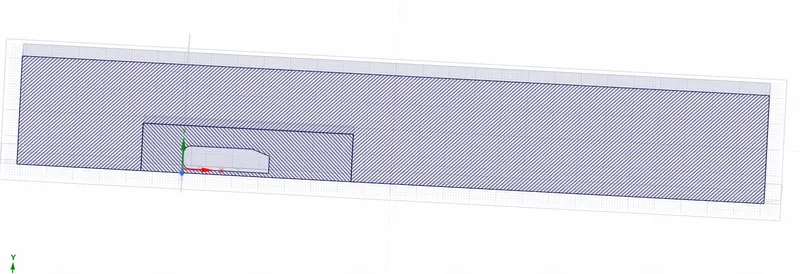
click generate Mesh.
mesh>>insert>>method >> multizone>>select outer body
click on mesh and give size as 100mm and also click insert >>body sizing>>inner body and give size as 50mm and click generate mesh
we need to mesh>>inflation select inner body >>selct car wall (named selection) >>first layer thickness>>5mm>>5 layers and click on generate mesh
open setup>> as for pressure based solver >>viscous>> K epsilon>>ok
inlet velocity>>20m/s
hybrid initialize the mesh
create contour for velocity and plots for drag and lift coefficient
have iteration of 500nos
go to cfd post to analyze vector plot
like this we are gonna flow anlyze for three different sizes
| outer body size | inner body size | |
| case 1 | 100mm | 50mm |
| case 2 | 80mm | 30mm |
| case 3 | 70mm | 25mm |
Now we are gonna analyze each and every case one by one.
OBSERVATION:
mesh:
case 1:
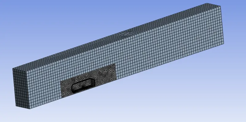 no of elements:60742
Case 2:
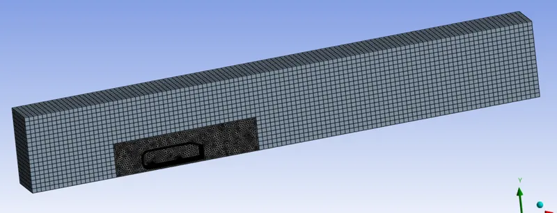 no of elements:217301
case 3:
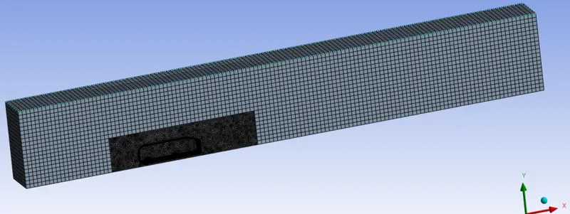 no of elements:361958
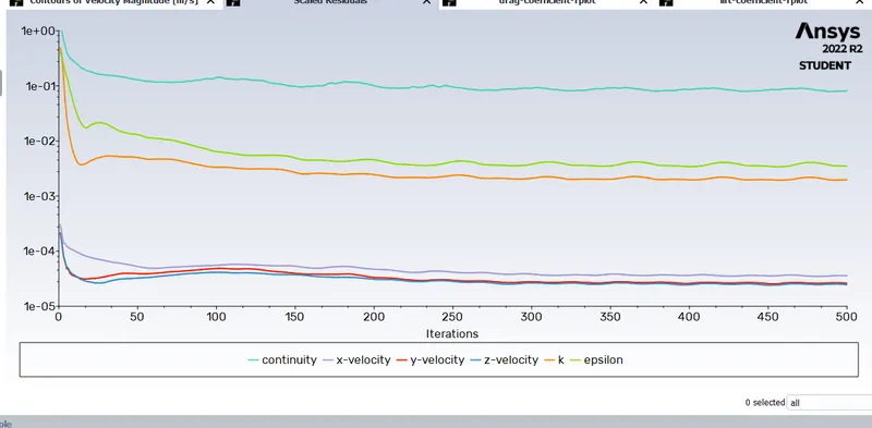
residuals
case 1:
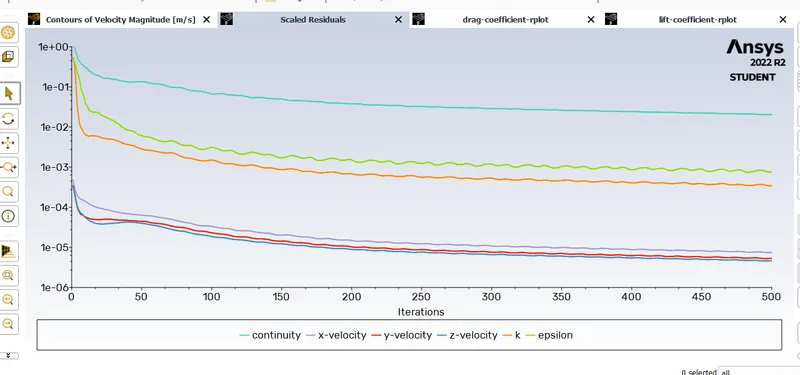
Case 2:
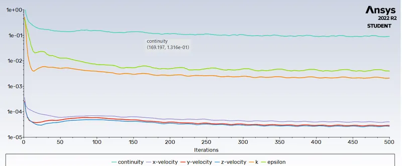
case 3:
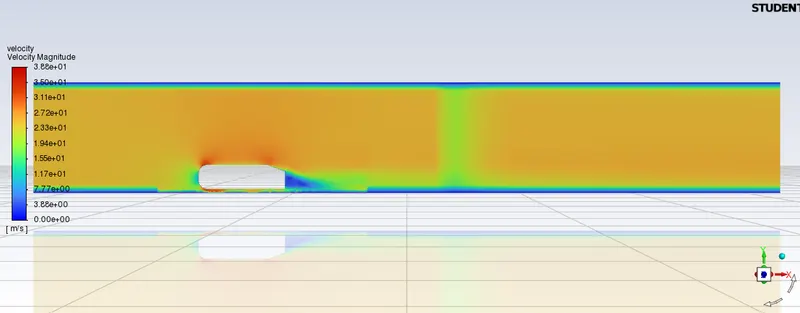
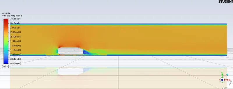
velocity contour
case 1:
case 2:
Case 3:
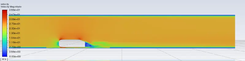
Observation: we can observe that case 3 is more finer behind the body such that zero velocity area is more clear.
drag and lift coefficient:
case 1:
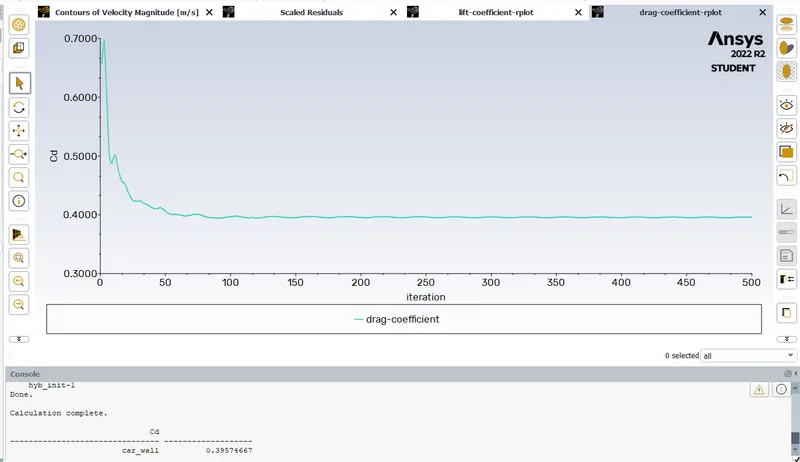
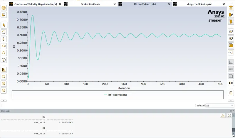
Cd=0.396
Cl=0.29
Case 2:
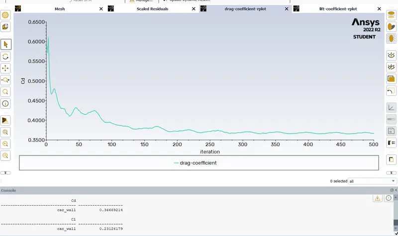
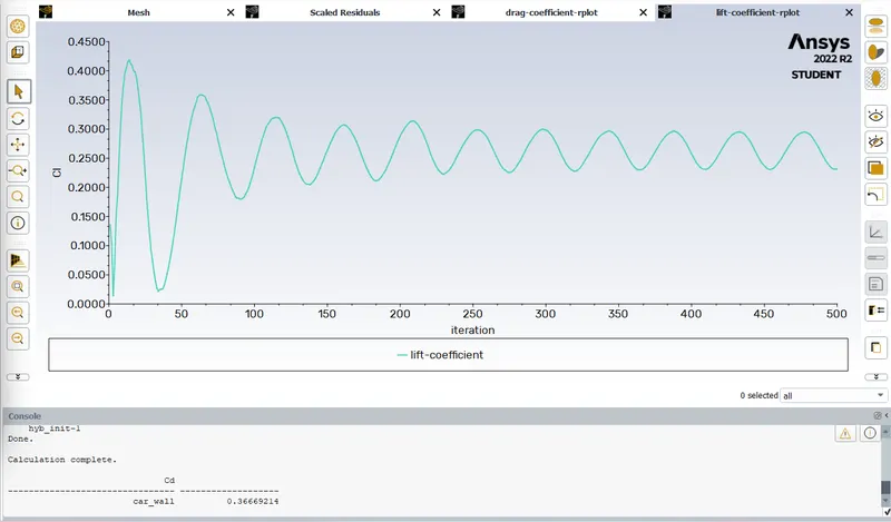
Cd=0.367
Cl=0.23
Case 3:
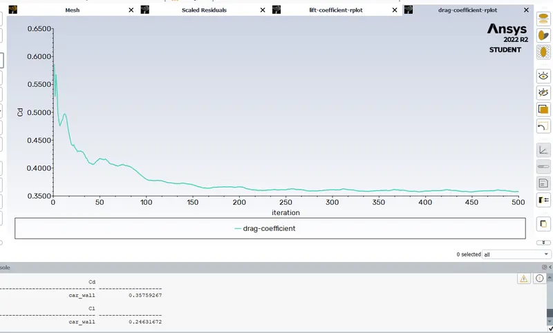
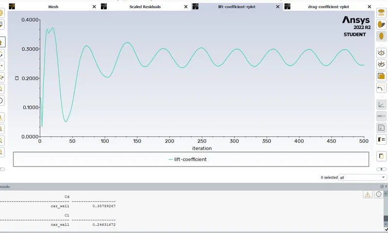
Cd=0.357
Cl=0.25
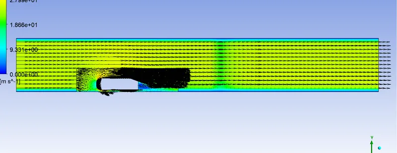
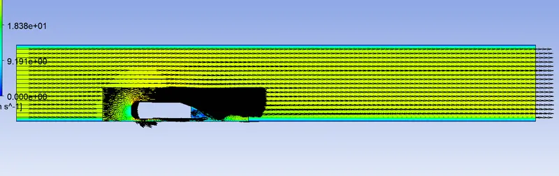
Vector plots:
Case 1:
Case 2:
Case 3:
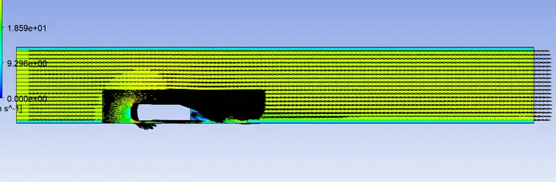
by observing all the vector plots it is clear that small size meshes produce good results and also shows wake region clearly.
conclusion:
| S.no | Case | outer mesh | Inner mesh | Cd | Cl |
| 1 | Case 1 | 100mm | 50mm | 0.396 | 0.29 |
| 2 | Case 2 | 80mm | 30mm | 0.367 | 0.27 |
| 3 | Case 3 | 70mm | 25mm | 0.357 | 0.25 |
by question it is given that drift coefficient will be 0.33
From the above results we can observe that case 3 gives closer value for calculated drift coefficient.
Hence we can ensure that smaller the mesh size the accuracy will be higher.
Results:
Thus we performed flow simulation over ahmed body.