Week 3 - External flow simulation over an Ahmed body.
Ahmed Body:
A generic car called Ahmed body which is perhaps the most widely studied simplified car model in the automotive industry. Several experimental and numerical studies on the Ahmed body indicate three major components in the wake of this body: A recirculation bubble over the slanted surface or rear window, one pair of counter-rotating longitudinal or C-pillar vortices originating from the two side edges of the rear window, and a recirculation torus behind the vertical base. Aerodynamic drag is directly linked to the interactions between these three types of
coherent structures. It was proposed a very simple and easily evaluative model with a cubical shape that no longer really looks like a car but reproduces its global behavior: a large 3D displacement in the front, a relatively uniform flow in the middle, and a large structured wake at the rear.
Ahmed body is a generic car body (a simplified car model) i.e the flow of air around the Ahmed body captures the essential flow features around an automobile. The aim of the benchmark validation was to evaluate the TCFD, computational fluid dynamics (CFD) software, and compare its results with the measurement data.
Geometry of the ahmed body:
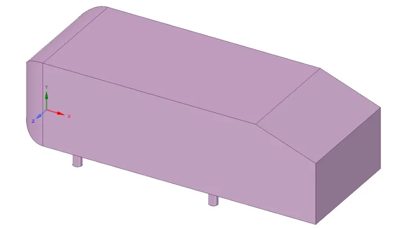
3-D view of the ahmed body.
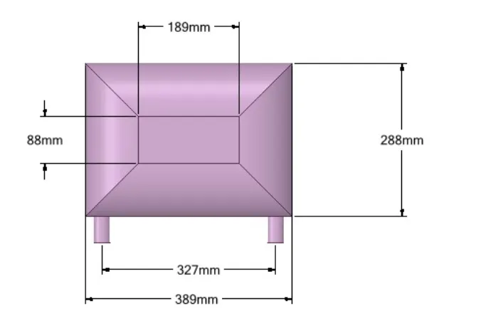
Front view of the ahmed body with dimensions.
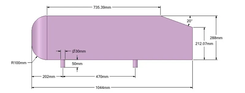
Side view of the ahmed body with dimensions.
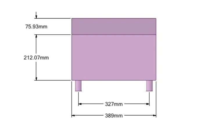
Rear View of the ahmed body with dimensions.
Negative pressure in wake region:
In fluid dynamics, a wake may either be:
- the region of recirculating flow immediately behind a moving or stationary blunt body, caused by viscosity, which may be accompanied by flow separation and turbulence, or
- the wave pattern on the water surface downstream of an object in a flow, or produced by a moving object (e.g. a ship), caused by density differences of the fluids above and below the free surface and gravity (or surface tension).
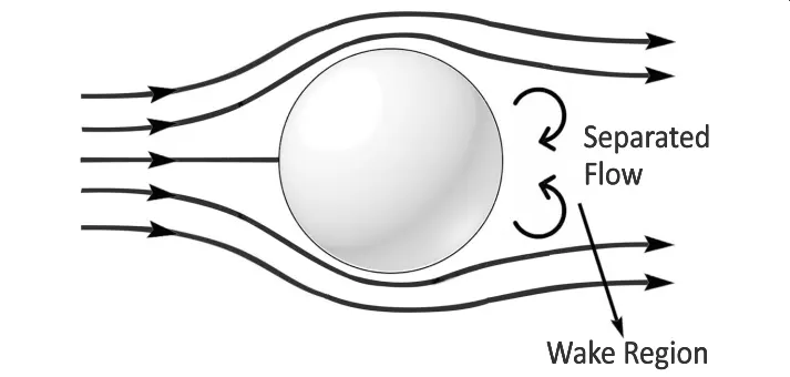
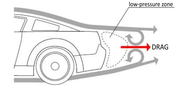
When the air moving over the vehicle is separated at the rear end, it leaves a large low pressure turbulent region behind the vehicle known as the wake. This wake contributes to the formation of pressure drag, which is eventually reduces the vehicle performance.
The region of recirculating flow immediately behind a moving or stationary blunt body, caused by viscosity, which may be accompanied by flow sepration and turbulence flow, or the wave pattern on the water surface downstream of an object in a flow, or produced by a moving object (e.g. a ship), caused by density differences of the fluids above and below the free surface and gravity.
Drag Force predominantly depends upon the velocity, frontal area, and coefficient of drag of the body. It can be expressed as:
`F_D= 0.5 C_(Dρ) A V^2`
Where FD is the drag force; ρ is the density of fluid medium that is air; A is the frontal area of the body facing the fluid; V is the velocity of the body; CD is the coefficient of drag of the body. In the similar context, lift force is of the major concerns too for design engineers, as excessive lift can make the vehicle loose traction at high speeds and can result in fatal injuries both to the driver and other pedestrians along with damage of public property. Thus, it is highly desirable the lift should be well within the stipulated range. Lift force can be expressed as:
`F_L= 0.5 C_(Lρ) A V^2`
Where FL is the lift force; ρ is the density of fluid medium that is air; A is the frontal area of the body facing the fluid; V is the velocity of the body; CL is the coefficient of lift of the body. From the drag equation, it can be seen that the drag force is in proportion to the square of the speed. This implies that the resistance due to air increases exponentially as the speed of the body increases. Flow separation control is also a major interest in fundamental fluid dynamics and various engineering applications. Flow Separation location determines the size of the wake area and the amount of aerodynamic drag is determined accordingly. When the air moving over the vehicle is separated at the rear end, it leaves a large low-pressure turbulent region behind the vehicle known as the wake. This wake contributes to the formation of pressure drag.
Significance of point of Seperation:
The separation point is the point where the air stops "sticking" to an object that is moving through the air. When an object is moving through the air, the air molecules push back on it and resist the object's movement - this resistance is called pressure drag. As the air flows around the object, it "sticks" to the object, forming what is known as the boundary layer. This "attached flow" is flowing very smoothly. The point on the body where the boundary layer lifts off the surface is called the separation point. When the air flow separates off the surface, the pressure drag usually increases.
In fluid dynamics, flow separation or boundary layer separation is the detachment of a boundary layer from a surface into a wake.
A boundary layer exists whenever there is relative movement between a fluid and a solid surface with viscous forces present in the layer of fluid close to the surface. The flow can be externally, around a body, or internally, in an enclosed passage. Boundary layers can be either laminar or turbulent. A reasonable assessment of whether the boundary layer will be laminar or turbulent can be made by calculating the Reynolds number of the local flow conditions.
Separation occurs in flow that is slowing down, with pressure increasing, after passing the thickest part of a streamline body or passing through a widening passage, for example.
Flowing against an increasing pressure is known as flowing in an adverse pressure gradient. The boundary layer separates when it has travelled far enough in an adverse pressure gradient that the speed of the boundary layer relative to the surface has stopped and reversed direction. The flow becomes detached from the surface, and instead takes the forms of eddies and vortices. The fluid exerts a constant pressure on the surface once it has separated instead of a continually increasing pressure if still attached.In aerodynamics, flow separation results in reduced lift and increased pressure drag, caused by the pressure differential between the front and rear surfaces of the object. It causes buffeting of aircraft structures and control surfaces.
The pressure distribution in the wake is quite different from that on the remaining boundary and this gives rise to an additional drag force on the body. Wake also leads to lateral vibration to the object which may be harmful. Also large amount of K.E. is lost.
Opening the geometry on SpaceClaim.
As the body is perfectly symmetric, we can run the simulation by considering only half the body. This is the best practice where you can save on the number of cells and get the results faster as well. The geometry which is provided with the challenge needs a modification which you should be able to do at this stage of a course. You need to use the 'split body' command in SpaceClaim to perform the operation and then you can use the symmetry boundary condition in fluent to perform the simulation.
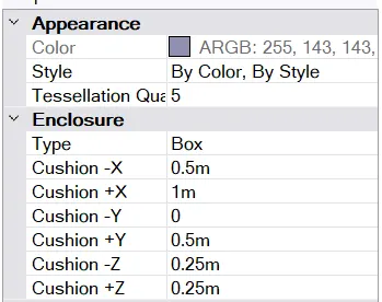
Enclosure number one, where the whole ahmed body has to be has to be enlosed under the parameters which is measured below.
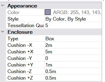
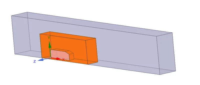
The below structure with orange boundary show the enclosure which has been done.
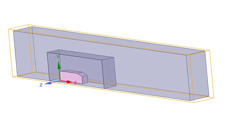
Enclosure number two, where the whole ahmed body has to be has to be enlosed under the parameters which is measured below which has to be done under the first enlosure.
The geometry with the orange colour shows the second enclosure which have done under the first enlcosure
Now, cutting the whole body into half based upon the refrenece to the 3 axis. This is the best practice where you can save on the number of cells and get the results faster as well.
When we simulate the ahmed body it is similar to the wind tunnel testing where the vehicle is simulated under the tunnel and only very rare parameters change.
Case 1)
In this the elemental size is equal to 0.1m.
Fluent Set up procedure:
- Update the mesh before opening the fluent setup and mesh checking should be done
- Take the k-epsilon turbulence model because we are taking the inlet velocity 25m/s which is smaller
- Consider the pressure density solver
- Take 25m/s as a velocity for the inlet boundary
- Then initialize the solution
- After initialize we should go to the post process to create a cut plane to see the velocity profile on it
- And create a contour plot for both pressure and velocity
- Also, create a plot for drag and lift using the definition tool
- And give the reference values for the Ahmed body
- Run the simulation for 150 iterations.
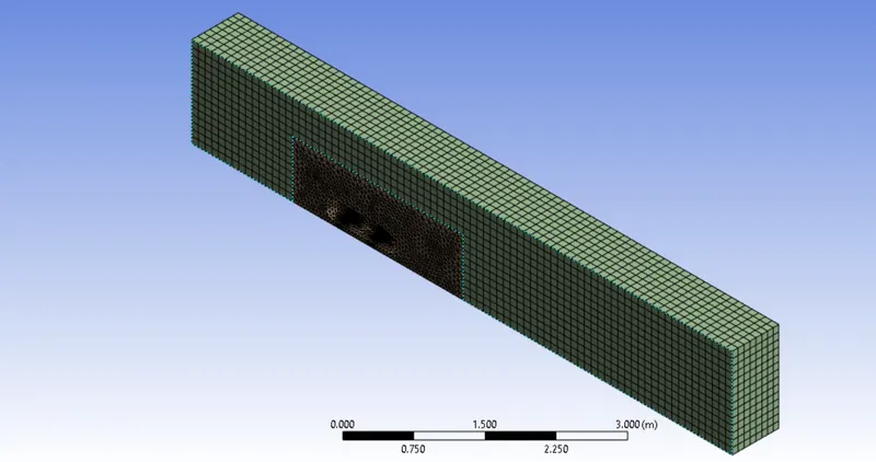
Meshing of the body is shown below:
3-D View of the meshing .
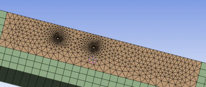
Bottom View of the Meshing
Parameters of the geometry is shown below.
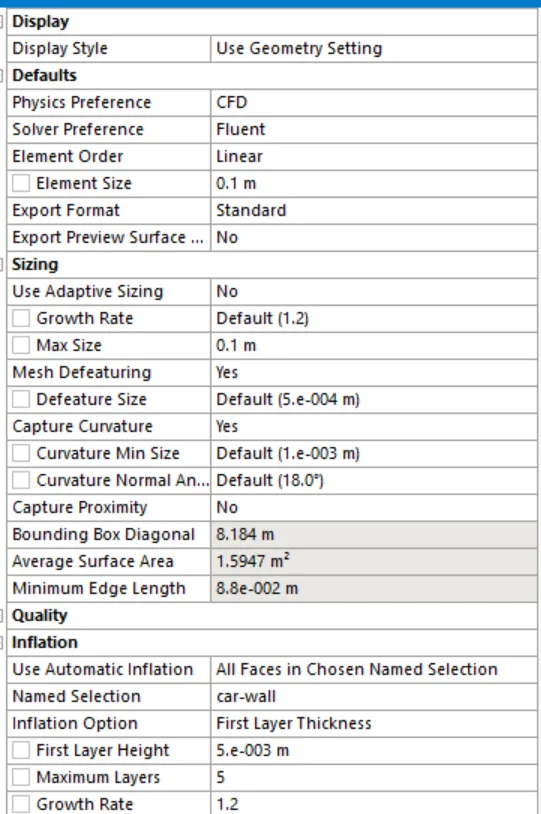
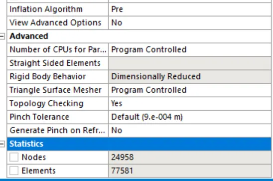
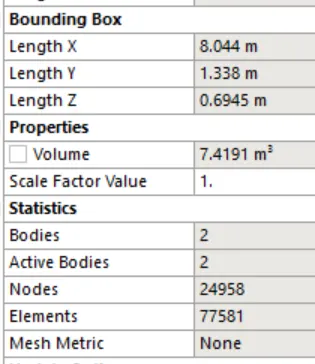
Size of the outer enclosure is shown below with volume and its dimensions.
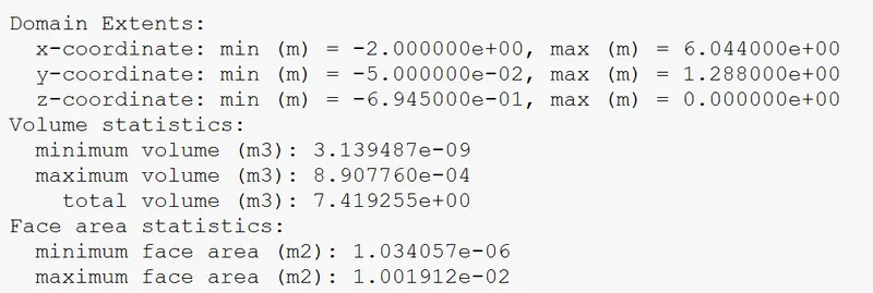
Coordinates of the geometry
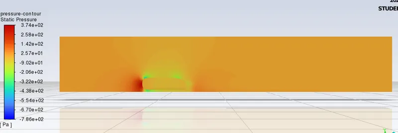
Pressure Contour of the geometry.
Residuals of the geometry:

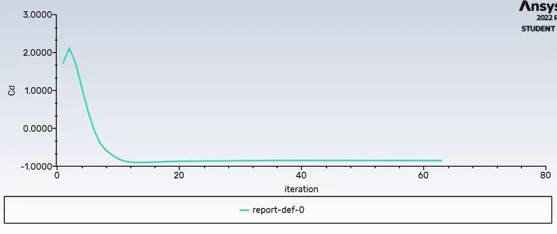
Coefficient of the drag.
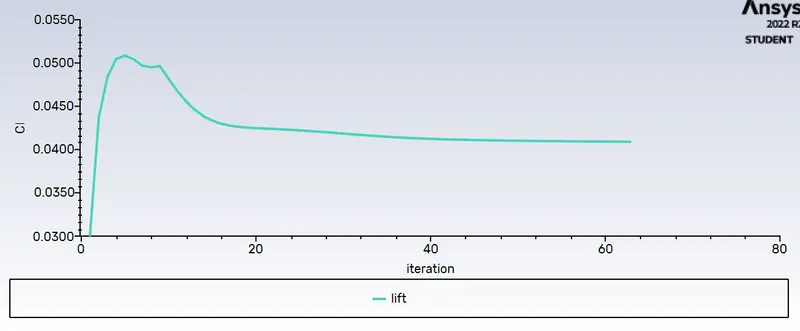
Coefficient of lift.
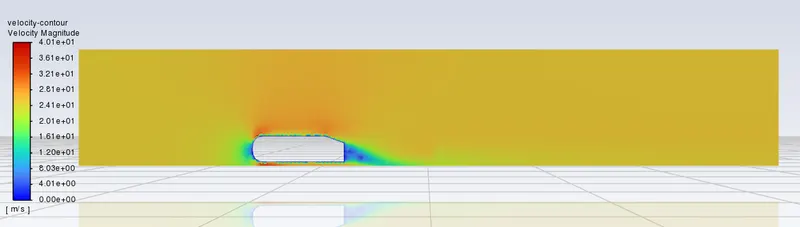
Velocity Contour
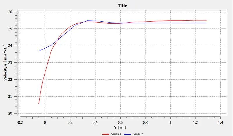
Velocity at distance of 3m and 2 m from the ahmed body.
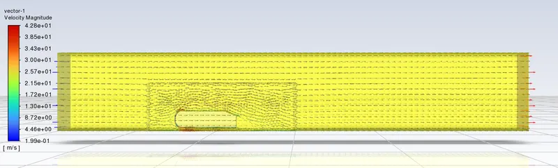
Vector velocity contour of the geometry
Case 2)
In this the elemental size is equal to 0.08m.
Fluent Set up procedure:
- Update the mesh before opening the fluent setup and mesh checking should be done
- Take the k-epsilon turbulence model because we are taking the inlet velocity 25m/s which is smaller
- Consider the pressure density solver
- Take 25m/s as a velocity for the inlet boundary
- Then initialize the solution
- After initialize we should go to the post process to create a cut plane to see the velocity profile on it
- And create a contour plot for both pressure and velocity
- Also, create a plot for drag and lift using the definition tool
- And give the reference values for the Ahmed body
- Run the simulation for 150 iterations.
Meshing of the body is shown below:
3-D View of the meshing .
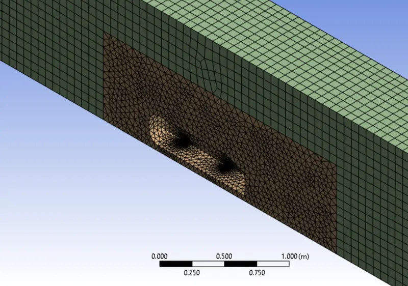
Bottom view of the mesh
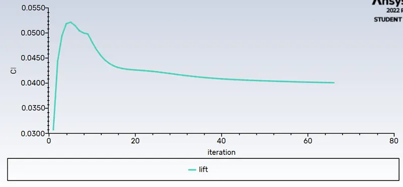
Plot for the coefficient of lift:
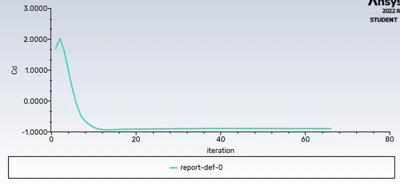
Plot for the coefficient of drag:
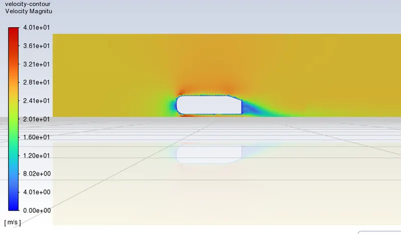
Velocity contour:
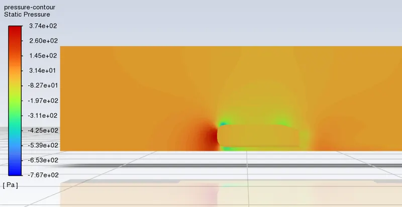
Pressure Contour:
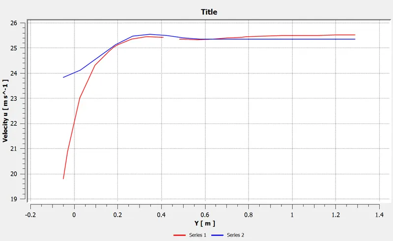
Velocity plot from a distance of 3m and 2 m from the ahmed body.
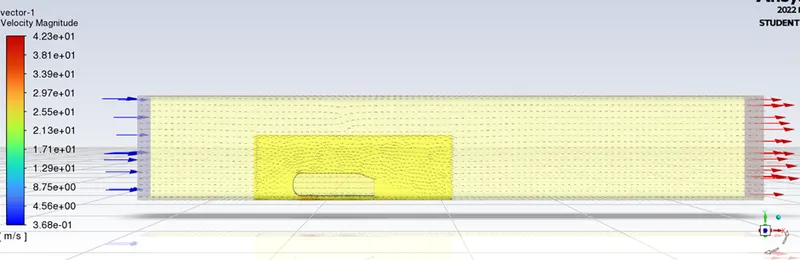
Velocity contour with vector plot:
Case 2)
In this the elemental size is equal to 0.06m.
Fluent Set up procedure:
- Update the mesh before opening the fluent setup and mesh checking should be done
- Take the k-epsilon turbulence model because we are taking the inlet velocity 25m/s which is smaller
- Consider the pressure density solver
- Take 25m/s as a velocity for the inlet boundary
- Then initialize the solution
- After initialize we should go to the post process to create a cut plane to see the velocity profile on it
- And create a contour plot for both pressure and velocity
- Also, create a plot for drag and lift using the definition tool
- And give the reference values for the Ahmed body
- Run the simulation for 150 iterations.
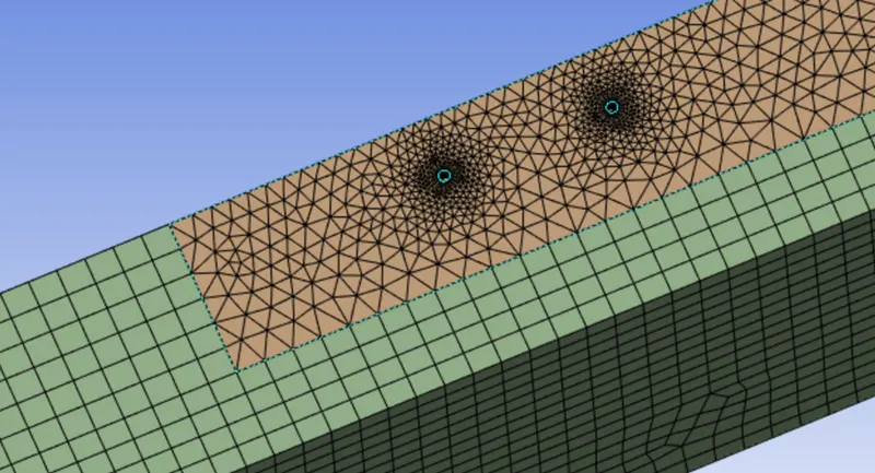
Meshing of the body is shown below:
3-D View of the meshing.
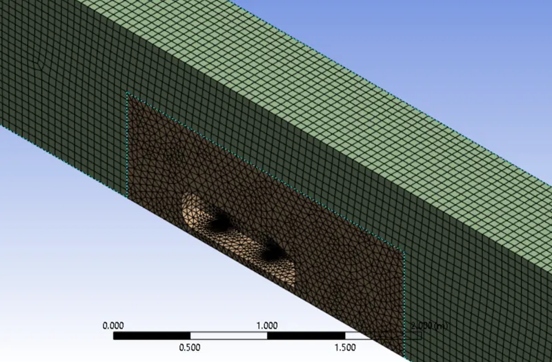
Bottom View :

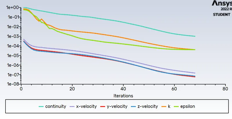
Residuals plot for the geometry:
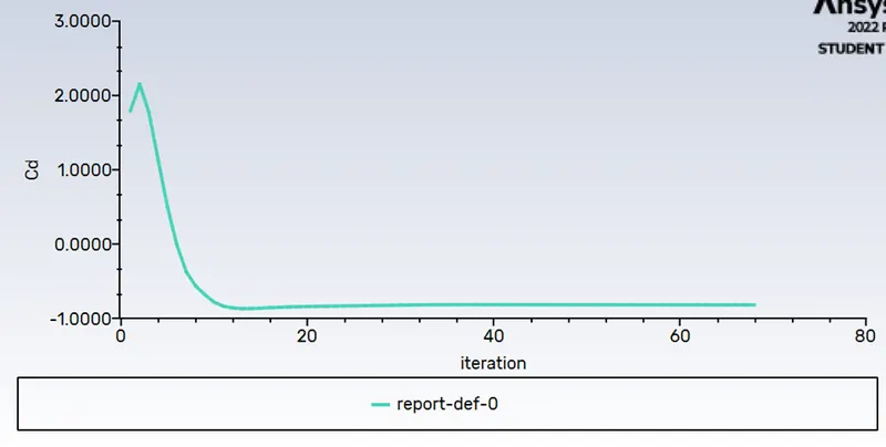
Plot for the coefficient of drag:
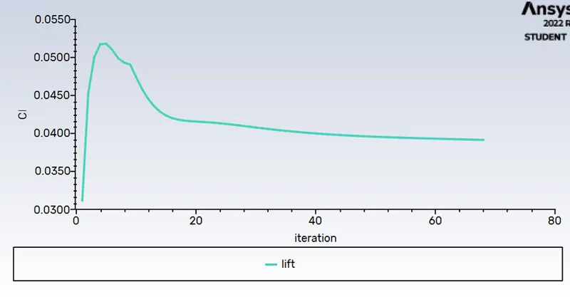
Plot for the coefficient of lift:
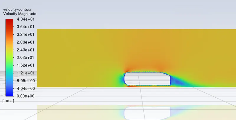
Velocity Contour:
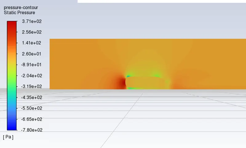
Pressure Contour:
Velocity plot from a distance of 3m and 2 m from the ahmed body.
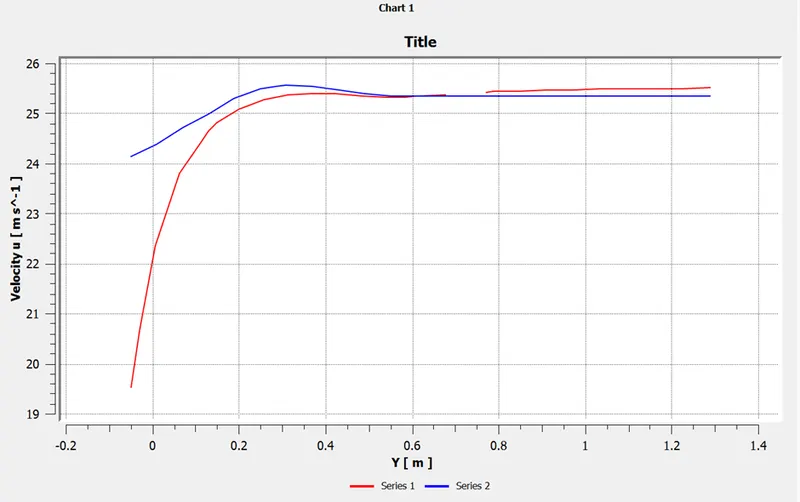
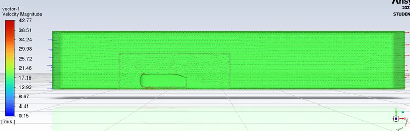
Velocity Contour with vector plot.
Grid Independency Test:
The grid independency test for the each case with the values of drag and lift can be defined below:
| Cases | Drag | Lift |
| 1 | 2.25 | 0.0515 |
| 2 | 2.1 | 0.0530 |
| 3 | 2.3 | 0.0520 |
From the above table with the refinement of the mesh for different cases the drag coefficient approaches closer to the analytical values that are because more cells are assigned at the boundary layer which results in more accurate results of drag coefficients.