Week 3 - External flow simulation over an Ahmed body.
Aim
Perform CFD simulation on the Ahmed body.
Introduction
The ahmed body is the very well known model used for almost replicating the 3D geometry of any general passenger car.
The body is mainly used for the validification of simulation model and software by comparing the results obtained from test software with the well known tried-&-tested results obtained before.
The Ahmed body is a geometric shape first proposed by Ahmed and Ramm in 1984. The shape provides a model to study geometric effects on the wakes of ground vehicles (like cars).
Theory
More specifically, standard wind tunnel models are used for:
1. confirmation of the reliability of the data from a new wind tunnel by comparison with results from other wind tunnel facilities;
2. providing baselines for correlation of results from different wind tunnels;
3. checkouts of data repeatability over time;
4. checkouts of data repeatability after repairs or modifications of the wind tunnel structure;
5 .assessment of the wall interference effects;
6 .identification of problems and faults in the operation of a wind tunnel;
7 .verification of new measurement techniques or devices;
8. training of wind tunnel personnel.
Besides, results from wind tunnel tests of standard models are used as test cases for verification of computational-fluid-dynamics (CFD) computer codes.
The process fluesnt fluid flow will be done in following these 5 steps:-
1) Geometry - The geometry of the model will be formed where the actual flow will flow/interfere
2)Mesh - The meshing of the volume is done whoose parameters are set by default with help of 'Boundary Box'
3)Setup - The initial and boundary conditions or parameters and the model choosen are given to the model.
4) Solutions - Based on conditions and requirements the result is calculated with the help of model choosen
5) Results - The final results are appeared here from where the investigation of simulation is done.
| Solving & Modelling approach |
For it's successfull optimal meshing and CFD simulation it would be a better decesion to use the ENCLOSURE around our Ahmed body for better results and comparaticely easy processing.
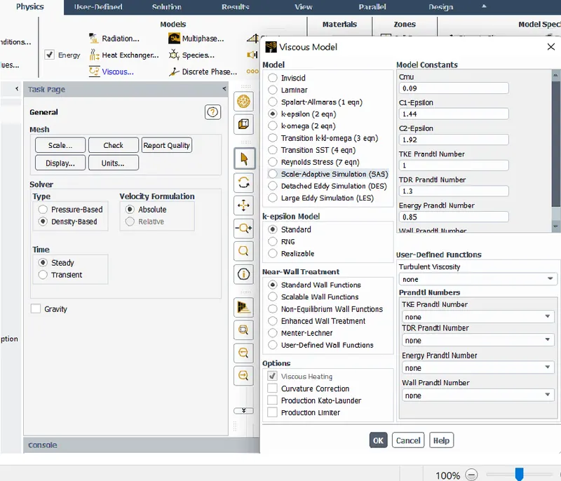
After the Meshing, the boundary conditions and the model to be choosen (in our case K-EPSILON) are given to our system according to the application and our requirements.
The results is formed based on the values of parameters given by us in graphical and CONTOUR form.
The result's appearance is manupilated according to our ease of comparison and analysis.
I have soved through the stages mentioned above with the help of videos shown and guidance of the technical staff and following the the steps below:-
Step 0) Download the model
Step 1) Make the best geometry as mesh requirement
1.1) Create 2 Enclosure around the body with 0mm base distence and other parameters as mentioned below according to sattisfy the wind tunnel need
1.2) Hide the car body and surpress it for physics
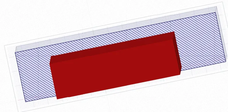
1.3) Remove the interfarance existing between enclosures
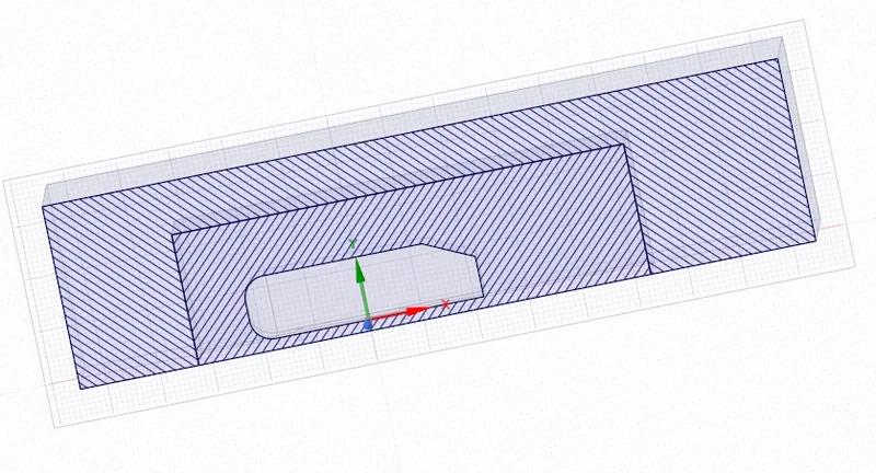
1.4) Make sure that there topo SHARES
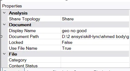
Step 2) Mesh the 3D model
2.1) Assign names
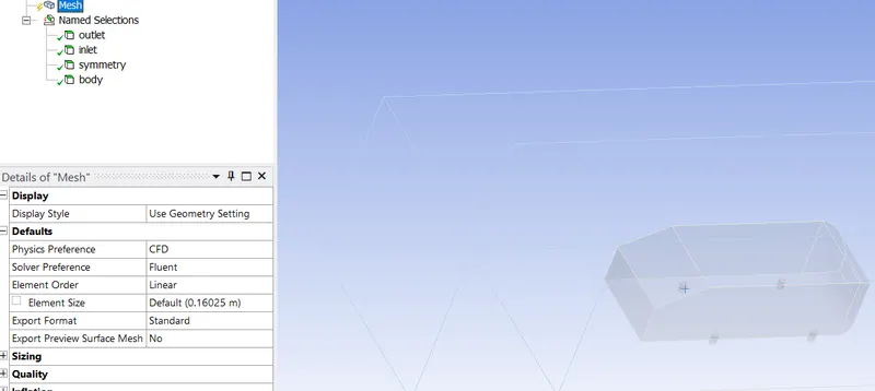
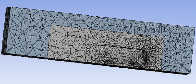
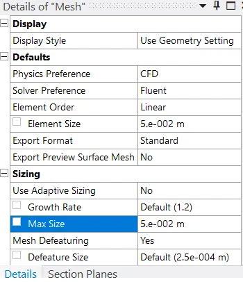
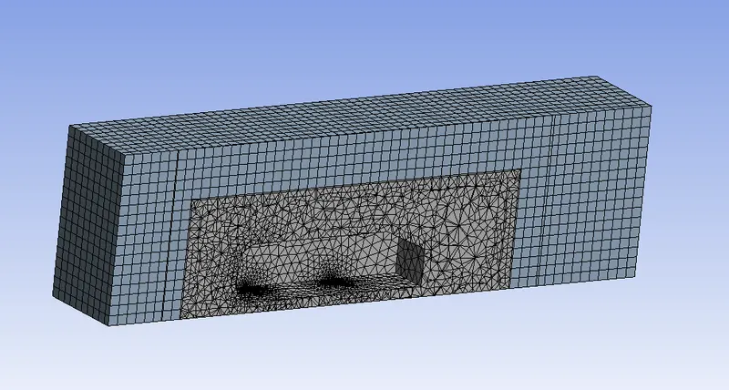
2.2) Assign Hexahedral mesh to the outer enclosure
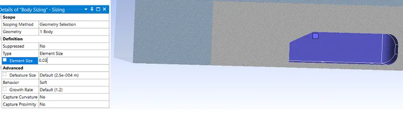
2.3) Insert sizing at the interference edge of 2 enclosures
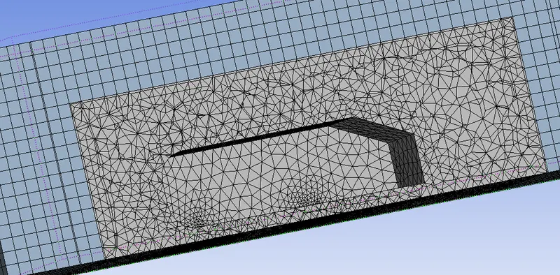
2.5) Solve the mesh around mesh column
BEFORE
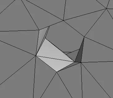
AFTER
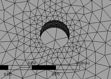
Procedure
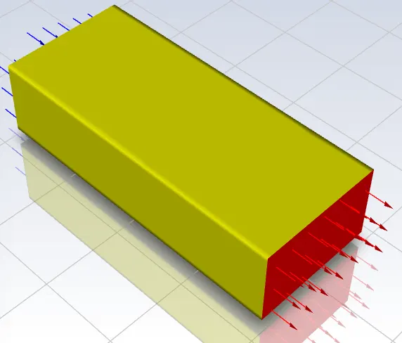
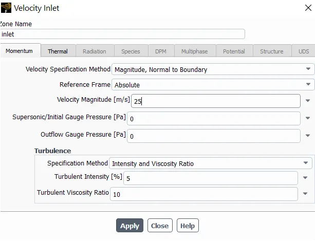
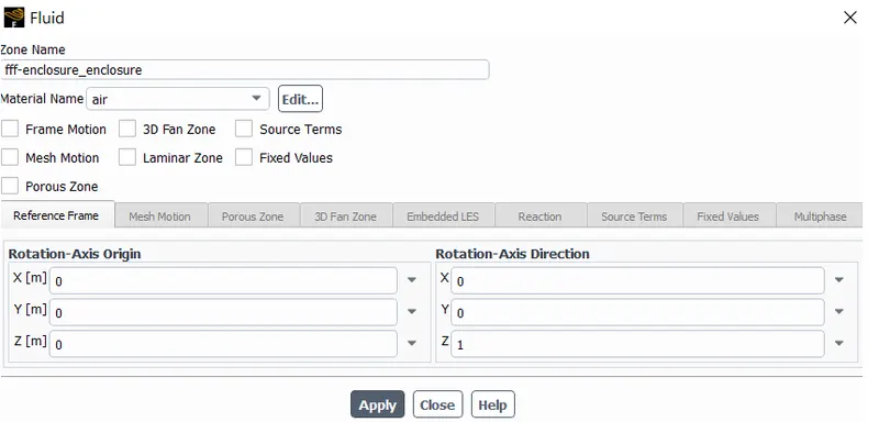
Step 3) Setup the conditions of our system
3.1) Give the physics parameters as given below
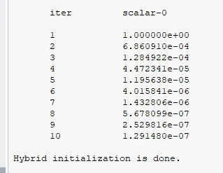
3.2) Hybrid initialize the system
3.3) Insert plane for result purpose at below given distance
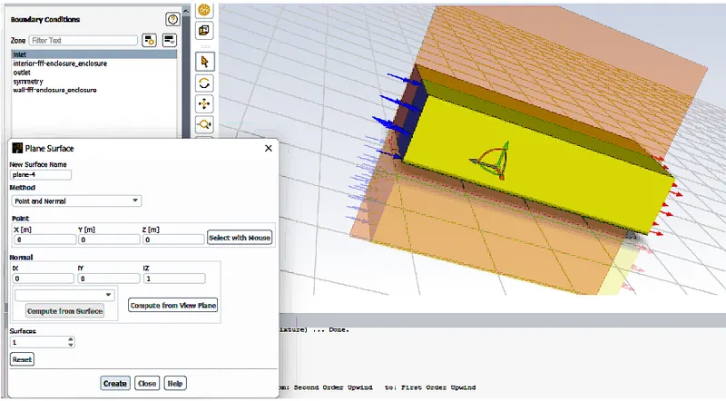
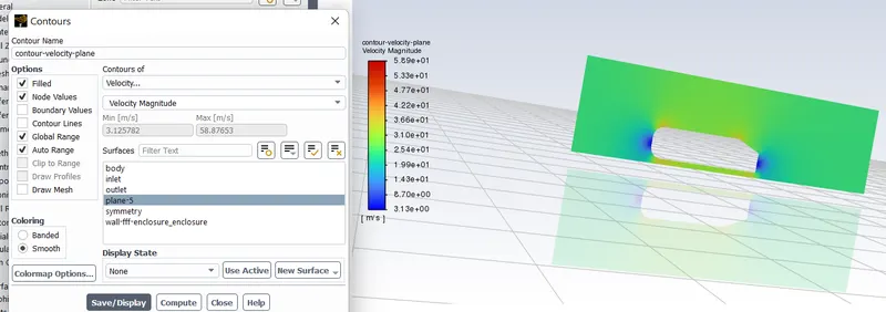
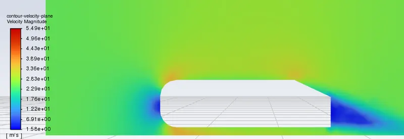
3.4) Give contours for velocity to the model
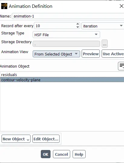
3.5) Execute animaatio by giving following parameters.
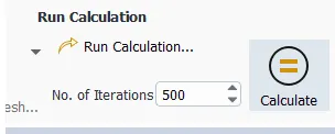
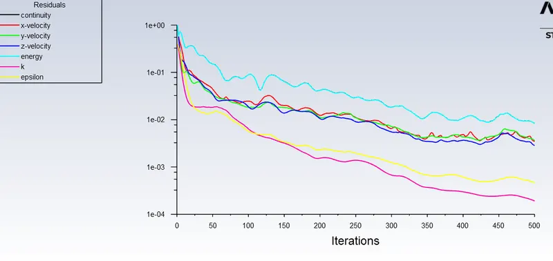
3.6) Run the setup with 500ITERATIONS
Step 4) Manupilate the result presentation the best way
4.1) Insert plane for velocity in the XY PLANE in car
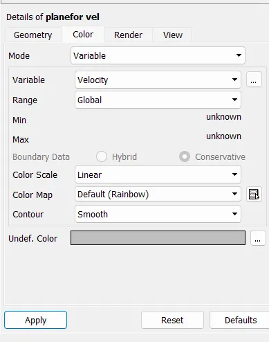
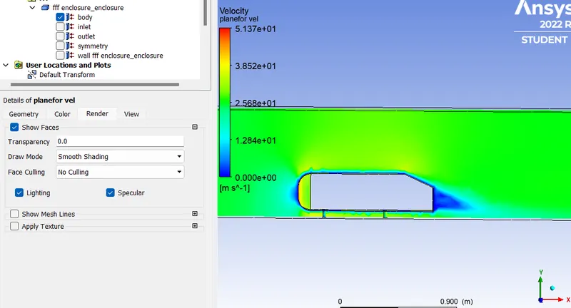
4.2) Render the plane depending on velocity

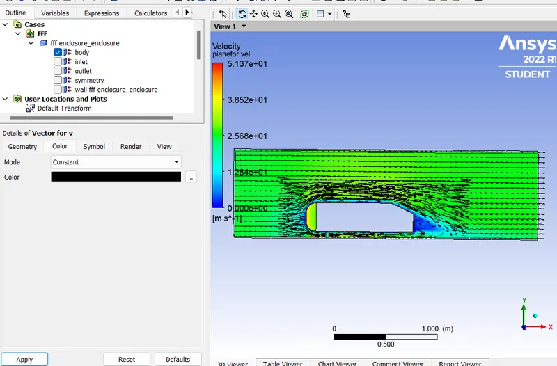
4.3) Add vectors to the plane
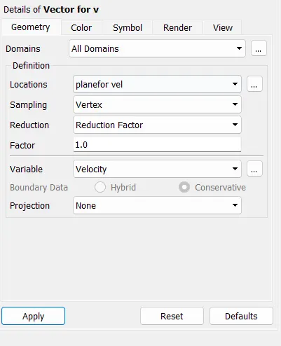
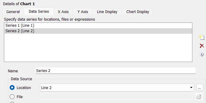
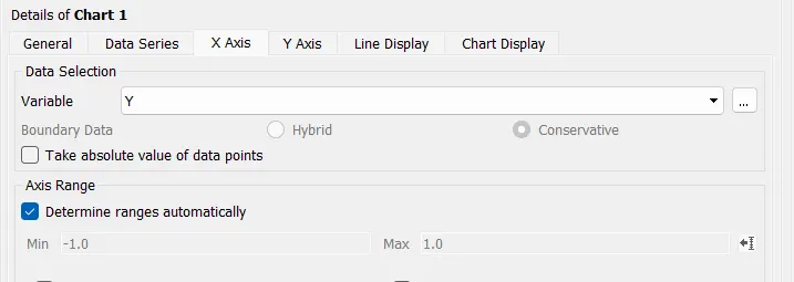
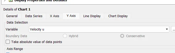
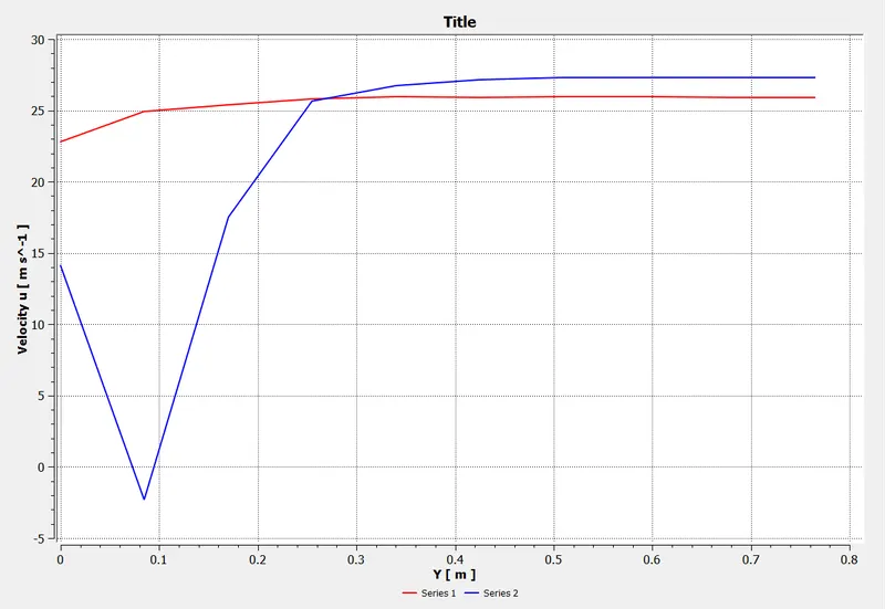
4.4) Show the 2 differreant position results on a chart


Results
1. The result for velocity distribution is fabricated, showing the velocity disturbance region. This can be also analysed with help of the vectors.
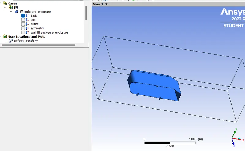
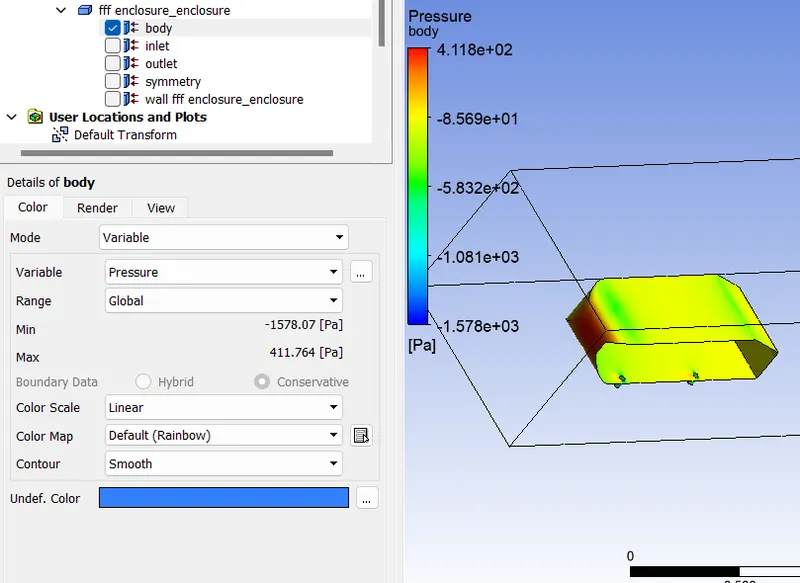
2. The pressure distribution can be seen in the car body
.
3. The chart shows the velocity difference b/w 2 points behind the car.
Ahmed body is a simplified car body and provides a model to study geometrical effects on the wakes of ground vehicles. This is the kind of baseline geometry for automobile bodies.
Reason for negative pressure in the wake region: The path lines showing the exact circular motion or vorticity generation just at the rear end of the car. The separation takes two regions of distribution. One at the upper part of the rear and the other at the lower part of the rear end.
The fluid separation point can be defined as a point where the dv/dy i.e. gradient of velocity goes zero along with the dp/dx = 0, for the specific point.
Conclusion
The following points can be concluded from the simulation performed:-
1. A high velocity flow over a sharp edge would cause flow seperation in that region.
2. High velocity regions cause low pressure regions, this pressure could be even lower than the atmospheric pressure and thus showing -ve pressure region.
3. Near the surface due to friction, laminar flow is distubed and improves as goes farther from the body surface.