Week 3 - External flow simulation over an Ahmed body.
Aim :
Run the simulation for the velocity of 25 m/sec with the default air properties in fluent.
Objective
1) Significance and importance of the Ahmed body.
2) To simulate the Ahmed body and calculate the coefficient of drag and lift also perform the grid dependence test.
Introduction
Two distinct regions created when the air tends to curl downwards at the rear of the vehicle.
(i) High pressure under the vehicle,
(ii) Low pressure on top,
While the airflow passed at the rear of the vehicle, there is a collision or interactions of both pressures results in a wake region. Kinetic energy from these turbulent air interactions tends to act in a direction which is opposite to the direction of travel. Resultant the car engine has to compensate energy losses as a result of the drag. During the flow separation period, vortices are created downstream forming either structured or unstructured wake patterns. Region of recirculation flow immediately behind a body that is caused by viscosity is known as a wake region. The aerodynamic forces created on a vehicle are as a result to various complex interactions between the flow separations and vortex wake’s dynamic behavior.
The Ahmed body is a generic car body or a simplified Automotive vehicle model. The essential flow has been captured by the airflow around the Ahmed body which features around an automobile and was first defined and characterized in the experimental work of S.R. Ahmed. Although it has a very simple shape, the Ahmed body allows us to capture characteristic features that are relevant to bodies in the automobile industry. This model is also used to describe the turbulent flow field around a car-like geometry. Once the numerical model is validated, it is used to design new models of the car.
The main goal of the automotive industry to reduce drag, keeping noise to a minimum, preventing lift (unwanted), and avoiding other unwanted instabilities that can occur at high speeds. Drag is a result of pressure differences between the frontal and the rear end of the vehicle. To reduce drag modifications of the vehicle design or modifications of the airflow around the vehicle. To conduct sufficient aerodynamic analysis in order to observe the behavior of turbulence and pressure, a simplified Ahmed body model will be analyzed. The body is a simplified bluff body that maintains a degree of accuracy when modeling airflow around the vehicle while maintaining great vehicle features.
The outcome for modeling and simulation of Ahmed Body
As we already mention that Ahmed body is the prototype of the automotive car and we run the simulation for calculating the drag and lift force on the Ahmed body. The resistance of an object in a fluid environment is quantified by the drag force. It varies with speed and direction of the flow, Object shape, and size and the density and viscosity of the fluid. The lower the drag coefficient of an object, The less aerodynamics or hydrodynamic drag occurs. In terms of a car, the lower the drag coefficient, the more efficient the car is. The wake flow behind the car is the location at which the flow separates determines the size of the separation zone, and consequently the drag force. So we need to do more exact simulation of the wake flow and of the separation process is essential for the correctness of drag predictions. However, a real-life automobile is a very complex shape to model or to study experimentally. Therefore the Ahmed body is best to use. This also helps to achieve efficient vehicles with minimized fuel consumption, CO2 emissions, and noise, while keeping good driving stability.
Also, Car with low drag is better but decreasing the drag drastically can reduce the downforce and lead to a loss in road traction and a higher and a higher chance of car accidents.
Methodology
- Meshing
- Pre-processing
-
Setting-up physics and solving
post processing
CASE 1 :
spaceclaim :
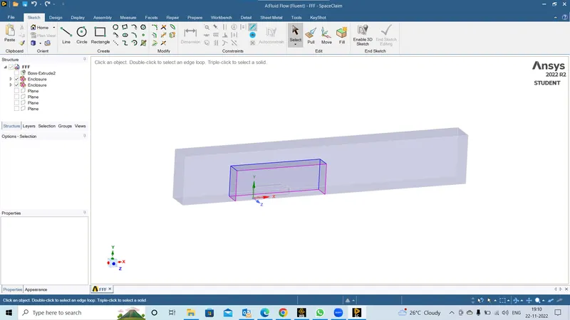
- In spaceclaim we are loading the given geometry,as per the given statement we are using half of the body to perform simulation since it is an symmetric in nature.
- the purpose of using half body is to reduce the time to perform the simulation.
- commands that we are using here for better simulation is we are creating 2 enclosure throughout the ahmed body.
- we are using split body option to make the body half as per the problem statement.
- We are using interference option here to a proper volume transaction between the enclosures.
- We are using topology command make sure to share the information from one enclosure to another enclosure in a proper way.
Meshing :
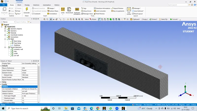
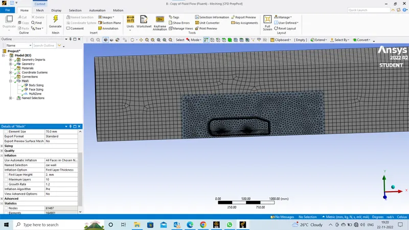
- in meshing we are giving 100 sizing for all the components initially then we did body sizing for the second enlosure and face sizing for the botton stands and creat inflation layers aroun the ahmed body.
- We are naming the initial and boundary condtions here to provide the the initial and boundary conditions in the solver
solver :
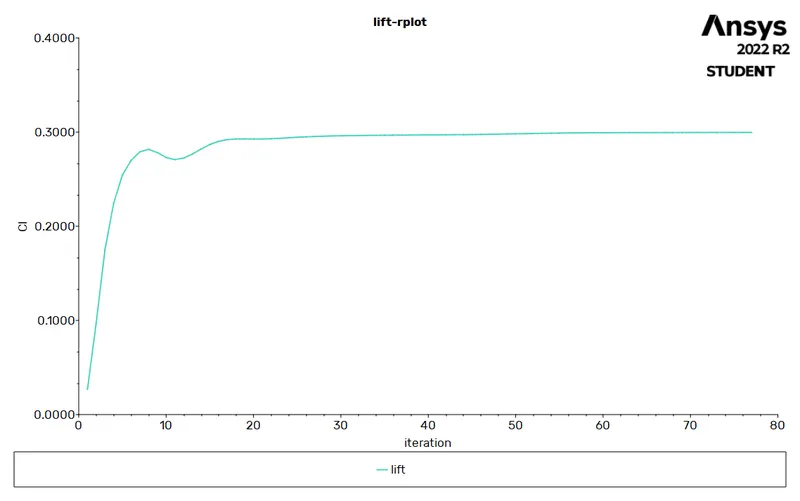
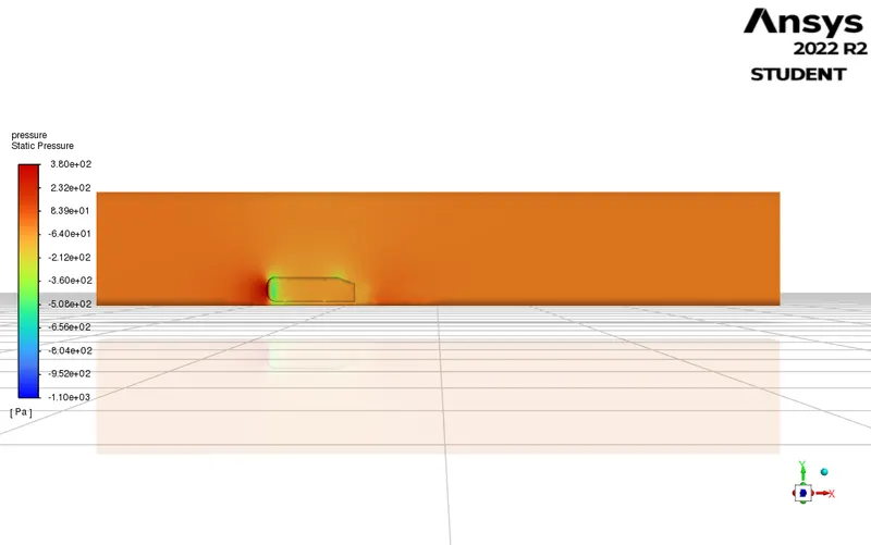
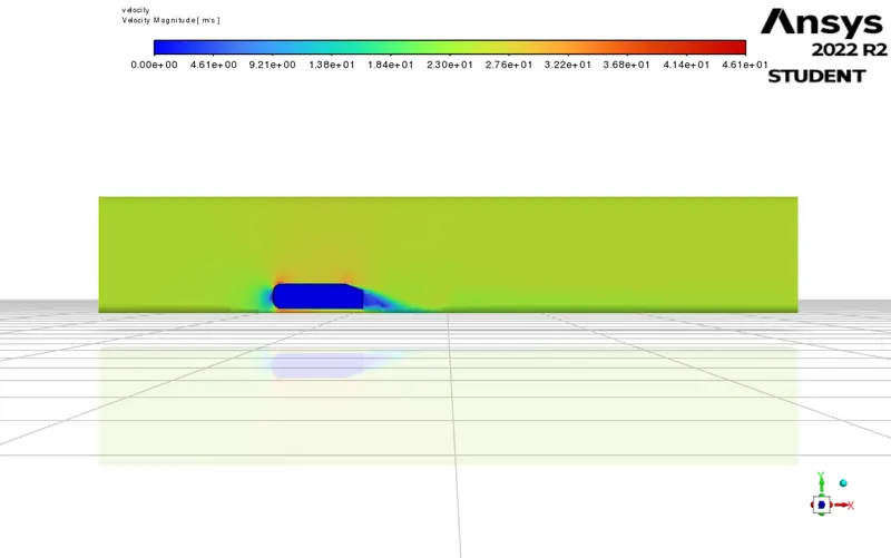
case 2:
MESHING :
solver :
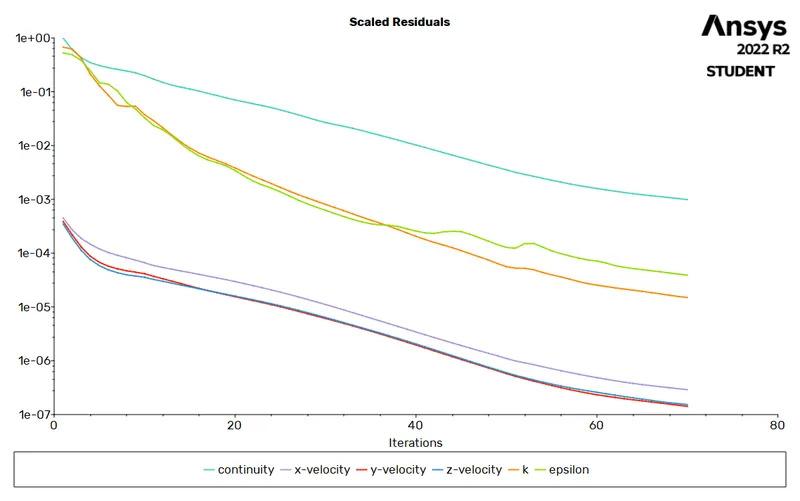
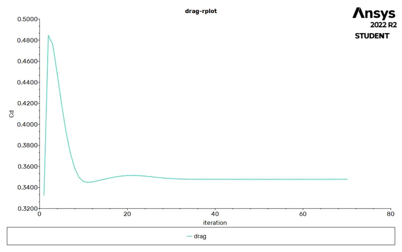
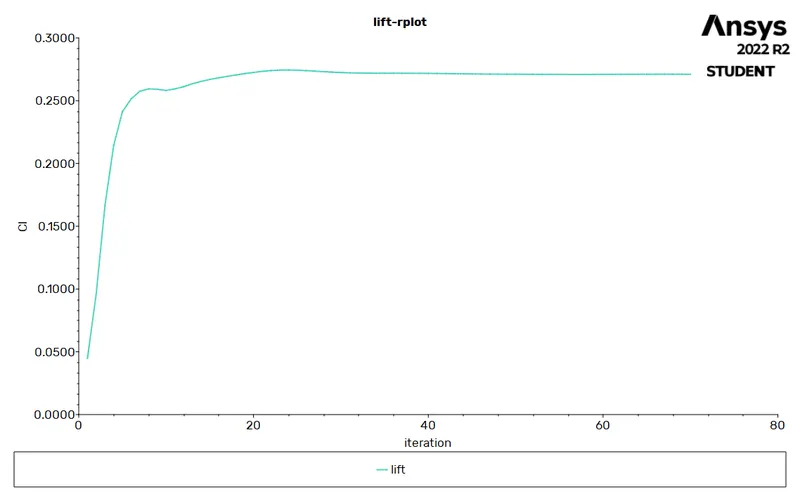
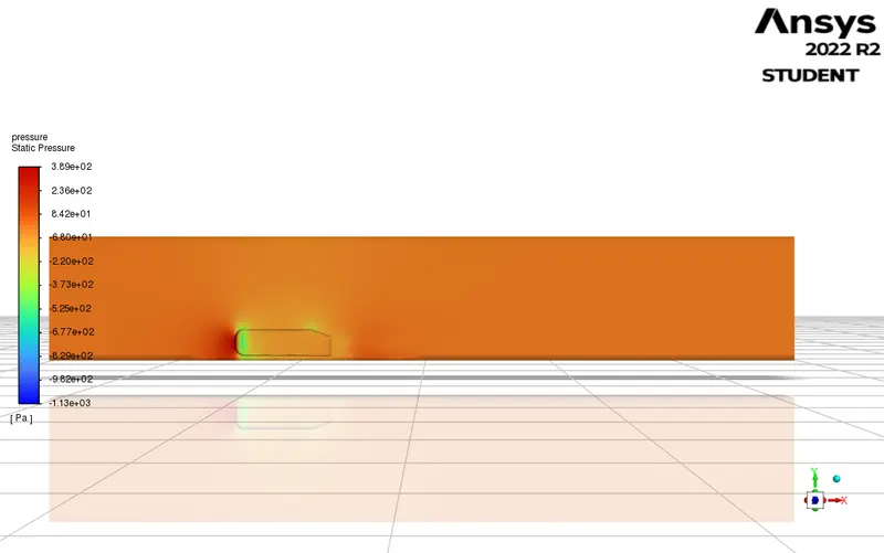
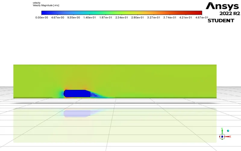
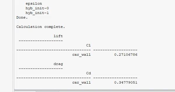
case 3:
Meshing :
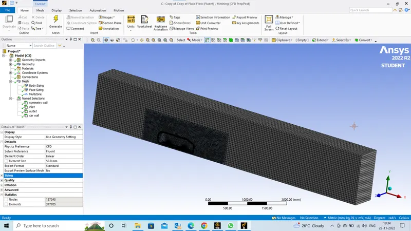
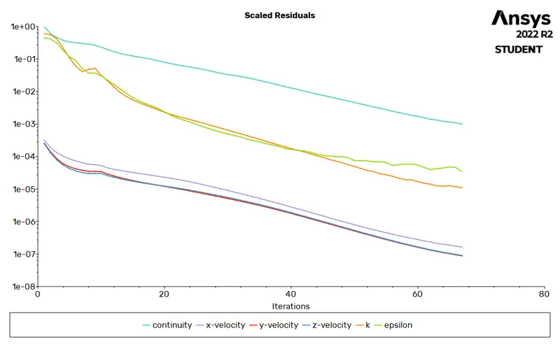
Meshing sizes for all the cases (all are in 'mm') :
i have started fron the course mesh and refined the mesh to get the accurate results
| case-1 | case 2 | case 3 | |
| element size | 100 | 70 | 50 |
| body size(2nd enclosure) | 50 | 50 | 30 |
| inflation(first layer thickness) | 2 | 2 | 2 |
| maximum layers | 10 | 10 | 10 |
| growth rate | 1.2 | 1.2 | 1.2 |
| face sizing (bottom stands | 8 | 5 | 3 |
fluent setup for all the cases :
| 1 | solver type | pressure based |
| 2 | solver time | steady state |
| 3 | energy | off |
| 4 | turbulance model | k epsilon |
| 5 | material | air |
| 6 | inlet | 25m/s |
| 7 | outlet | pressure outlet |
| 8 | car wall | ahmed body |
| 9 | side faces of enclosure | symmetry wall |
| 10 | method | couppled |
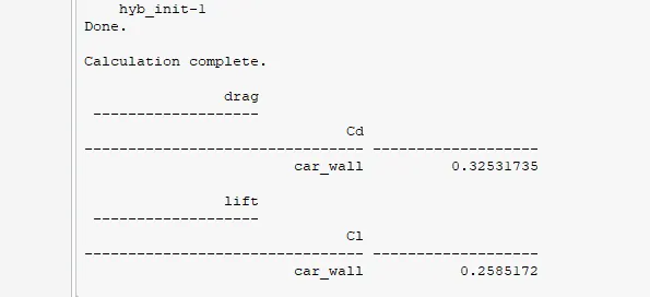
comparing the lift and drag coefficient for all the cases :
| case 1 | case 2 | case 3 | |
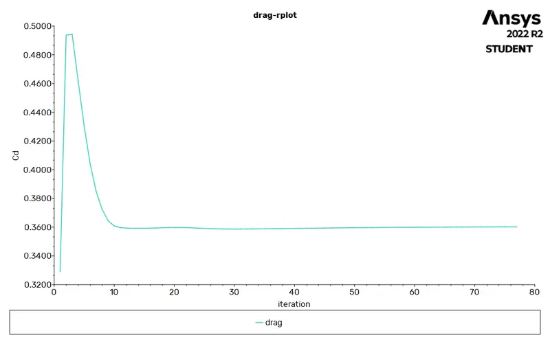
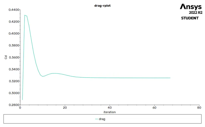
| drag-coefficient | 0.3602 | 0.3477 | 0.3253 |
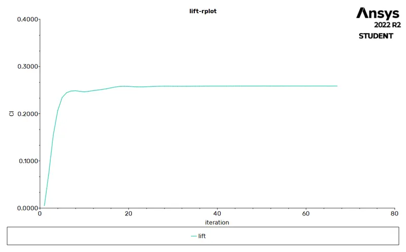
| lift-coefficient | 0.2996 | 0.2710 | 0.485775 |
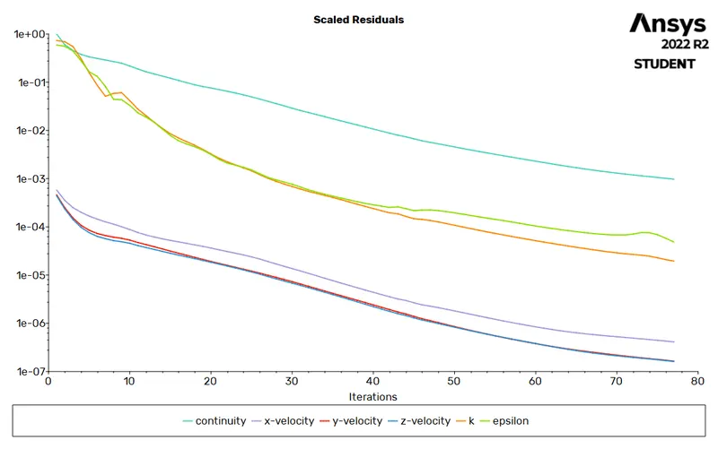
for the third case we have refined a mesh more so we are simulating by using almost 377705 elemnts we are heading to more accurate results of drag and lift.
from the above results we have obeserved that the more number of elements leaads to a accurate results but it will take more simulation time to get the results.
decreasing the element size causes to increase the elements size and it causes to increase the simulation time.
Reason for the negative pressure in the wake region
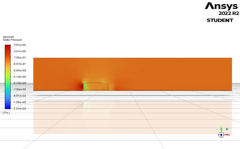
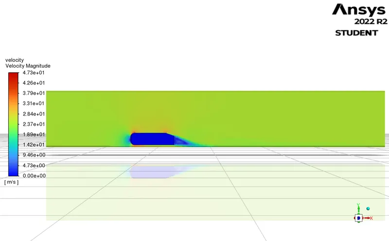
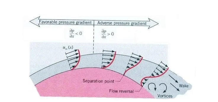
When velocity flow is higher, there should be low pressure. And in Ahmed body simulation case, the pressure is high enough to detach layer from the body while velocity and shear stress becomes zero and create a wake region There is a negative velocity gradient and shear stress due to the flow circulation which causes reversible highly turbulent flow as shown in velocity vector contour. But fluid has to move against the adverse pressure gradient resultant there should be low pressure inside the wake reason which responsible for drag force.
Significance of point of separation
The point of separation in turbulent flow is the detachment of a boundary layer from a surface into a wake in an external flow problem. Due to the friction forces, velocity starts decreasing and also gets an increase in pressure. Flowing against an increasing pressure is known as flowing in an adverse pressure gradient. The boundary layer separation starts when it has traveled far enough in an adverse pressure gradient so that the speed of the boundary layer relative to the surface has stopped and reversed direction. So the flow separation occurs and takes the forms of eddies and vortices. After separation, the fluid exerts only constant pressure. In other words, Flow separation occurs due to the pressure difference on the front and rear surface of the body.
Due to flow separation, an increase in pressure drag, and a reduction in lift occur.
Inference
1) Ahmed body is used as an automotive prototype. Once we calibrate this simulation from the experimental data, we can use the solver for complex automotive structures.
2) Mesh refinement gives more accurate results (Coefficient of drag and lift). But we should care about it and without proper justification don't take too many cells because it increases the computational time.
3) For selecting a y+ value, it should be noted that the error in the drag coefficient should not more than 30% for a normal refined mesh. After getting a proper y+ we should be refined our mesh for getting accurate results.
4) Negative pressure rises in the wake due to reversible highly turbulent flow which will be responsible for the drag force.
5) Flow separation occurs due to the pressure difference on the front and rear surface of the body.