Week 3 - External flow simulation over an Ahmed body.
AIM:
To study the external flow simulation over the Ahmed body.
OBJECTIVE:
- Perform the grid independency test and provide the values of drag and lift with each case.
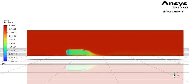
- Velocity and pressure contours.
- The vector plot clearly shows the wake region.
- An explanation for the negative pressure region in the wake region and the significance of the point of separation.
THEORY OF AHMED BODY:
One main contributor to fuel burn is the car’s aerodynamic drag. Complexly shaped, cars are very challenging to model and it’s difficult to quantify the aerodynamic drag computationally. The Ahmed body is a benchmark model widely used in the automotive industry for validating simulation tools.
Ahmed body is a simplified(generic) car body in that the flow of external air around the Ahmed body captures the essential flow features such as pressure, velocity, etc.
Why is it called Ahmed body S R Ahmed in is research some salient features of the time-averaged ground vehicle wake in 1984. Since then, it has become a benchmark for aerodynamic simulation tools. The simple geometrical shape has a length of 1.044 meters, a height of 0.288 meters, and a width of 0.389 meters. It also has 0.5-meter cylindrical legs attached to the bottom of the body and the rear surface has a slant that falls off at 40 degrees.
The drag coefficient quantifies the resistance of an object in a fluid environment. It is not an absolute constant for a body’s shape because it varies with the speed and direction of flow, object shape and size, and the density and viscosity of the fluid.
Importance of AHMED BODY
The general purpose of ANSYS fluent software is to compute the CFD simulations which indeed predicted the behavior of the system. These numerical predictions need to be validated by experimental data. People working in vehicle aerodynamics use Ahmed's body to validate their numerical model because the experimental data from wind tunnel testing is available for Ahmed's body. Once the numerical model is invalidated, it is used to design new models of the car.
Three main features were seen in the wake:
- The recirculation region is formed due to the separation at the base of the model.
- The pillar vortices that form as the vorticity in the side boundary layers roll up over the slant edges.
- The recirculation region is formed as the flow separates at the top of the vertical back surface of the model.
Its shape is simple enough to allow for accurate flow simulation but retains some important practical features relevant to automobile bodies.
This model describes how to calculate the turbulent flow field around a simple car-like geometry using the Turbulent Flow, k-epsilon, and k-omega interface. Later, either experimentally or computationally it can be recreated all the same but with the desired geometry, new to come up to the market or research.
DETAILED PROCEDURE FOR SIMULATING THE AHMED BODY USING ANSYS FLUENT
AHMED body geometry
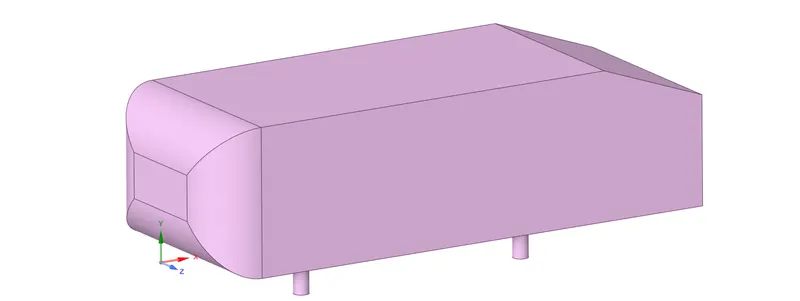
In ANSYS fluent we have three major steps to solve CFD problems Pre-processing, Solver, and Post-processing.
- Pre-processing involves cleaning up the models and generating the mesh here its geometry, mesh.
- Solver involves setting up the problem statements such as solver used, boundary conditions, methods, report definitions, etc here the solver used in Ansys is setup.
- Post-processing involves obtaining the simulated contours, graphs, and animations here in Ansys it is Results.
In GEOMETRY
- Initially, I am importing the Ahmed body (.STEP) file into the space claim.
- Next in order to the parameters such as velocity, the pressure I am creating the external and internal enclosure(Why internal enclosure is to reduce the number of mesh elements and for better capturing of the physics taking place nearer to the Ahmed body).
- External and internal enclosures are created as shown below with the following dimensions.
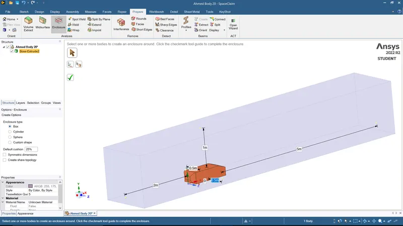
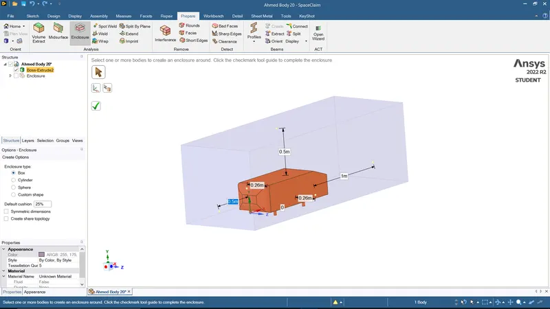
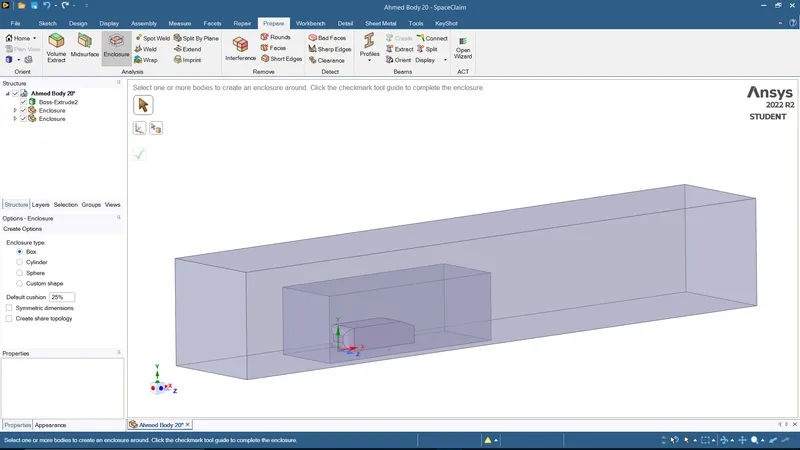
- We are creating the planes at the origin point in order to get the cut section for the enclosures.
- Also, we do not require Ahmed's body hence we are going to suppress(only the fluid domain). To get the cut section view there is a cut section view and select the selection mode=>select the plane.
- The hatching lines of the external surface are overlapped with an internal surface. Hence we use the interference option from prepare tool option=> to select the appropriate area as shown below.
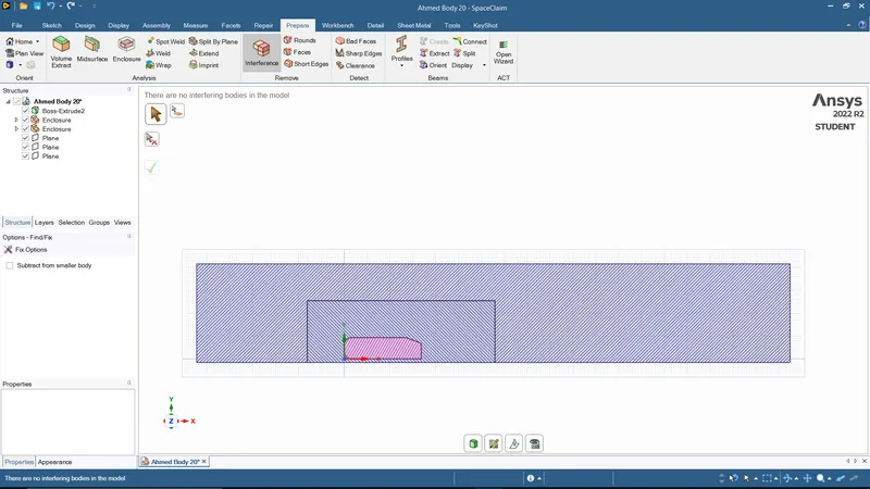
- Share topology is done for information exchanges between both enclosures. This is done by selecting the share option under the workbench.
- Finally, a split body is used to reduce the number of mesh element sizes for simulation purposes. This is done under prepare tool=> select split by plane=>select the body and respective plane. Once this is done we close the window and move on to meshing.
In MESH
Here we use the grid independence study to obtain the drag and the lift coefficients. Grid independence study is general by varying the mesh element size for both external and internal enclosures to obtain valid results(to get accurate results).
Case study 1: External enclosure mesh size(250mm) and internal enclosure mesh size(100mm).
Case study 2: External enclosure mesh size(100mm) and internal enclosure mesh size(50mm).
- For the external enclosure, we will sizing mesh option=> insert=>sizing methods(give respective mesh size) similarly internal enclosure, we will sizing mesh option=> insert=>sizing methods(give respective mesh size).
- Select the cavity region in order to capture the physics, and select the faces to give mesh size.
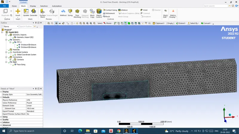
Creating INFLATION LAYERS
- Before creating the inflation layers we have to do name selection which is for inlet, outlet, symmetry, and car wall.
- Next, we are creating the inflation under the mesh options=>under automatic inflations=>select all the faces in chosen name selection option=>under named selection=>car wall=> inflation option=>first layer thickness(0.4m)=>under number of layers(6)=>select update the mesh.
SETUP AND SOLUTION
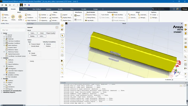
- In this, we provide fundamental physics, types of solver, boundary conditions, and type of turbulent model used.
- Initially, we go for the SOLVER option here we are the type of solver used is PRESSURE BASED SOLVER (M<0.3), and since the variable is not varying with respect to time select the STEADY STATE option.
- In the following step in for the PHYSICS, the window selects the VISCOUS option we get the window opened up. Here we are selecting the type of viscous model which is a TURBULENT model (k-epsilon) and near wall treatment, we are using the enhanced wall treatment option(for capturing better physics).
- We are giving the BOUNDARY conditions for the inlet velocity as 25m/s.
- Give reference values for the simulation from the inlet.
- The wall has a no-slip boundary whereas the top and bottom are in symmetrical boundary conditions.
- The hybrid method is used for initialization.
- Note that SOLUTION and SETUP windows are the same we can compute the results from the solution window. But for our convenience, we open the RESULTS window to obtain the solution to the Ahmed model.
RESULTS
- Once the RESULTS window is opened we select the PLANE option to obtain the pressure and velocity at the midsection of the model and do an XY PLANE cut.
- Then for obtaining the contour plot for variation of velocity and pressure across the length, Under PLANE we do a COLOR option to change the VARIABLE option to temperature.
Case study 1: External enclosure mesh size(250mm) and internal enclosure mesh size(100mm).
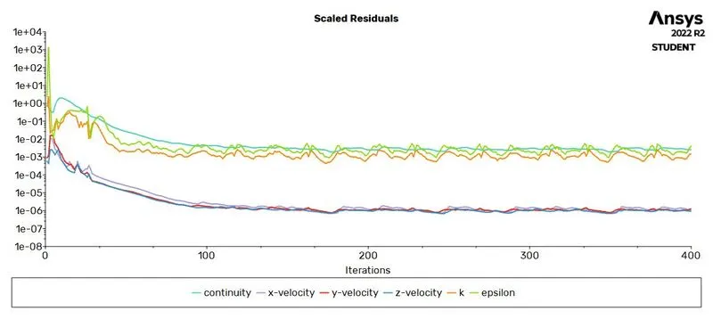
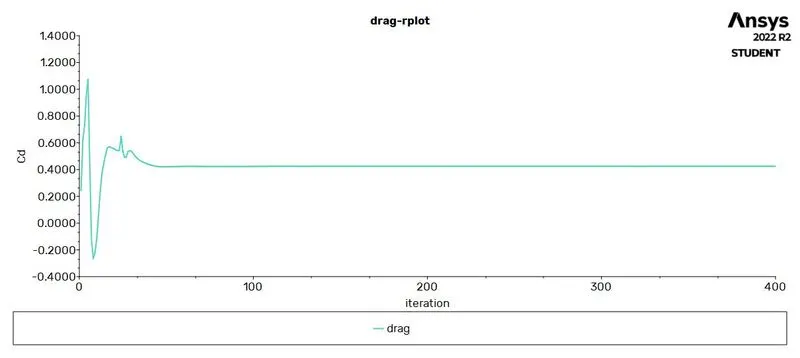
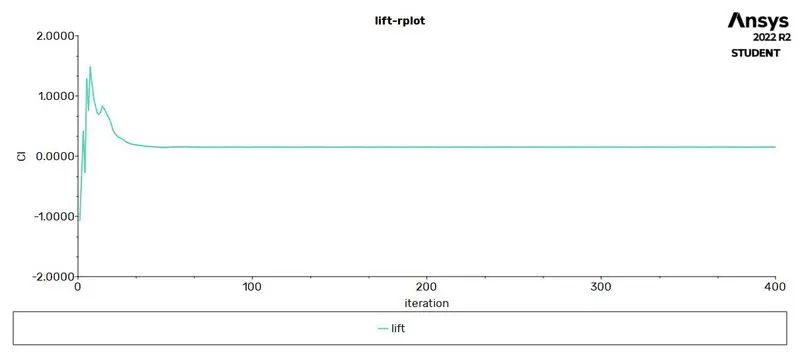
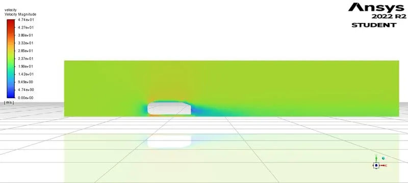
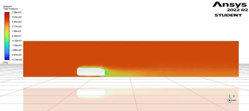
This simulation was run for 400 iterations results are shown below
Scaled residual plot
Drag plot
lift plot
velocity contour
total pressure contour
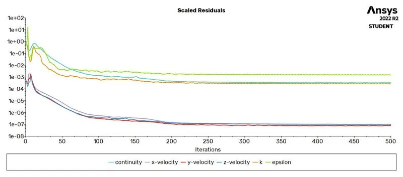
Case study 2: External enclosure mesh size(100mm) and internal enclosure mesh size(50mm).
This simulation was run for 400 iterations results are shown below
Scaled residual plot
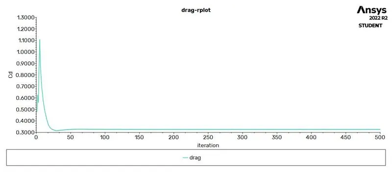
Drag plot
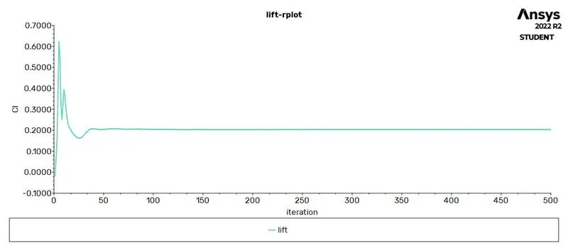
lift plot
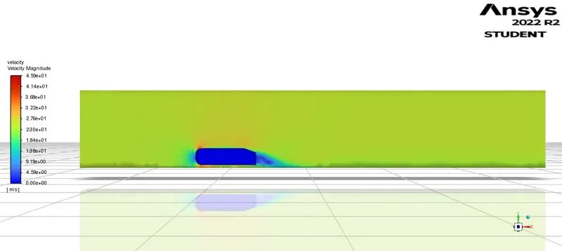
velocity contour
total pressure contour
| NUMBER OF ELEMENTS | DRAG COEFFICIENT(Cd) | LIFT COEFFICIENT(Cl) |
| 60036 | 0.424 | 0.150 |
| 162000 | 0.327 | 0.206 |
NEGATIVE PRESSURE IN THE WAKE REGION:
The negative pressure is due to the velocity difference applied at a certain Reynold number and the rear angle, which is at a low Reynolds number when this difference in pressure happens the wake obtained increases the drag due to the pressure drop behind the Ahmed body, which at a high Reynolds number due to the vortices generated it produces small amounts of pressure thrusting the body.
SIGNIFICANCE OF POINT OF SEPARATION:
The point of separation defined by the Ahmed body and the flow, the alpha angle(ANGLE BEHIND THE AHMED MODEL) depending on which value is at it causes a change in the flow direction, forces required, lift on the body, induced drag due to tip vortex, at a critical value flow in slant stalls and reduced lift-reducing as well drag, all depending on the value of alfa and the Reynolds number.
CONCLUSIONS:
- The refined mesh gave better results. The plots show the wake formation accurately and the flow around Ahmed's body was also captured pretty well.
- There is a variation of pressure across Ahmed's body. The pressure in front of the body is positive because that's the location where the flow first comes in contact with the body and comes to rest.
- The baseline mesh gave a poor result, it wasn't able to capture the flow around Ahmed's body and the wake structure, due to coarse mesh.
- As the wake flow is the main contributor to the drag force(pressure drag), the point of separation is an important aspect of the flow. The more attached the flow is to the body the recirculation zone will be smaller and hence reduce the adverse effect of pressure drag
- The reason behind negative pressure in the wake region is due to flow separation, and recirculating flow. It's a phenomenon that generally happens as the air moving past the body isn't able to pass through the immediate backside of the body creating a region, where there is no movement of air and thereby creating a pressure gradient.