Week 3 - External flow simulation over an Ahmed body.
Week 3 - External flow simulation over an Ahmed body.
Aim:
- To describe Ahmed's body and its importance.
- To explain the reason for the negative pressure in the wake region.
- To explain the significance of the point of separation.
Expected Results:
- To display velocity and pressure contours.
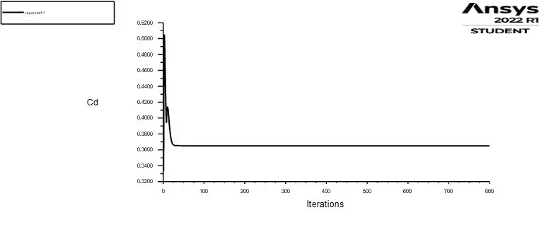
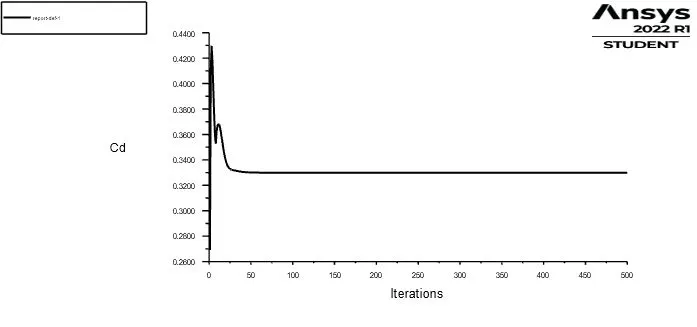
- To display the drag coefficient plot for a refined case. ( For velocity of 25m/sec, the drag coefficient should be around 0.33).
- To display the vector plot, that clearly shows the wake region.
- To perform the grid independency test and provide the values of drag and lift with each case.
Introduction:
Ahmed Body:
The automobile industry is evolving as well as flourishing in the entire world day by day. This development has massive impact on air pollution and climate change in our planet. Developing aerodynamically efficacious vehicle will reduce the fuel consumption and it is the major way to mitigate air pollution and climate change crisis in the world.
The Ahmed body is a generic car body (a simplified vehicle model). The airflow around the Ahmed body captures the essential flow features around an automobile and was first defined and characterized in the experimental work of Ahmed. Although it has a very simple shape, the Ahmed body allows us to capture characteristic features that are relevant to bodies in the automobile industry. This model is also used to describe the turbulent flow field around a car-like geometry. Once the numerical model is validated, it is used to design new models of the car.
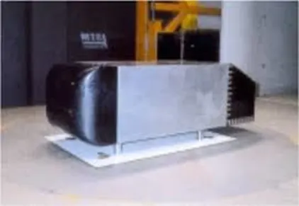
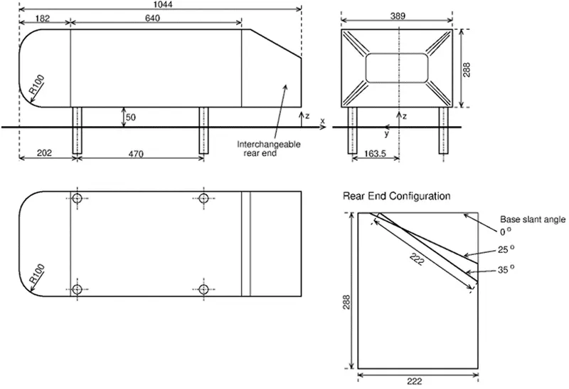
Ahmed body is simplified car model created by Ahmed et in the 1980s to investigate the behavior of newly developed turbulence models for complex geometry cases. The Ahmed body is made up of around front part, a movable slant plane placed in the rear of the body to study the separation phenomena at different angles, and a rectangular box, which connects the front and rear slant plane as shown. Ahmed body is a simplified model of a car body, but it demonstrates all the flow features involved in an actual case of a moving car. Current vehicle development needs a strong background in aerodynamics to improve flow control by means of active or passive control devices. The complexity involved in the automobile design especially due to the great number of accessories and devices that form its geometry makes the validation tasks unaffordable. The Ahmed model is a simple geometric body that retains the main flow features, especially the vortex wake flow where most part of the drag is concentrated and it is a good candidate to be used as a benchmark test.
The Ahmed body represents a simplified, ground vehicle geometry of a bluff body type. Its shape is simple enough to allow for accurate flow simulation but retains some important practical features relevant to automobile bodies. Selection of the configuration of this body is governed by the requirement that it should generate the essential features of a real vehicle flow field except for the flow fields that occur due to rotating wheels, engine and passenger compartment, rough underside and surface projections. The model chosen would generate strong 3-D flows in front relatively uniform flow in the middle and a large structured wake at the rear.
Drag:
It is the common force that a body meets some resistance when it is forced to move through a fluid. We could notice that we feel difficult to walk in water because of the much greater resistance it offers to motion compared to air. A fluid may exert forces and moments on a body in and about various directions. The force a flowing fluid exerts on a body in the flow direction is called drag. The drag forces can be measured directly by simply attaching the body subjected to fluid flow to a calibrated spring and measuring the displacement in the flow direction experimentally. The most researches have been centred around the reduction of drag. Reduction of drag is closely associated with the reduction of fuel consumption in automobiles. But in certain cases, drag produces a beneficial effect and we try to maximize it.
Drag force is proportional to the velocity for low-speed flow and the squared velocity for high-speed flow, where the distinction between low and high speed is measured by the Reynolds number. Drag forces always tend to decrease fluid velocity relative to the solid object in the fluid's path.
The drag depends on the density of the fluid, the upstream velocity, size, shape of the body. The drag co-efficient is calculated by using the following formula.
`F_D=1/2 *rho*v^2*C_D*A`
where
`F_D` is the drag force
`rho` is the density of the fluid
`v` is the velocity of the fluid
`A` is the cross sectional area
`C_D` is the drag co-efficient.
Lift:
A fluid flowing around an object exerts a force on it. Lift is the component of this force that is perpendicular to the oncoming flow direction. It contrasts with the drag force, which is the component of the force parallel to the flow direction. Lift conventionally acts in an upward direction in order to counter the force of gravity, but it can act in any direction at right angles to the flow.
The lift co-efficient is calculated by using the following formula.
`F_L=1/2*rho*v^2*C_L*A`
where
`F_L` is the lift force
`rho` is the density of the fluid
`v` is the velocity of the fluid
`A` is the cross sectional area
`C_L` is the lift co-efficient.
Ahmed Body Geometry:
The reason for the negative pressure in the wake region:
When the air moving over the vehicle is separated at the rear end, it leaves a large low pressure turbulent region behind the vehicle known as the wake. This wake contributes to the formation of pressure drag, which is eventually reduces the vehicle performance. The region of recirculating flow immediately behind a moving or stationary blunt body, caused by viscosity, which may be accompanied by flow separation and turbulence flow, or the wave pattern on the water surface downstream of an object in a flow, or produced by a moving object (e.g. a ship), caused by density differences of the fluids above and below the free surface and gravity.
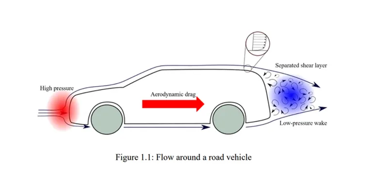
When the vehicle is moving at a certain velocity, the viscous effects in the fluid are restricted to a thin layer called boundary layer. Outside the boundary layer is the inviscid flow. This fluid flow imposes pressure force on the boundary layer. When the air reaches the rear part of the vehicle, the fluid gets detached. Within the boundary layer, the movement of the fluid is totally governed by the viscous effects of the fluid. The Reynolds number is dependent on the characteristic length of the vehicle, the kinematic viscosity and the speed of the vehicle. The fluid moving around the vehicle is dependent on the shape of the vehicle and the Reynolds number. There is another important phenomenon, which affects the flow of the car and the performance of the vehicle. This phenomenon is commonly known as ‘Wake’ of the vehicle. When the air moving over the vehicle is separated at the rear end, it leaves a large low-pressure turbulent region behind the vehicle known as the wake. This wake contributes to the formation of pressure drag, which is eventually reduces the vehicle performance.
The significance of the point of separation:
Flow separation is a common phenomenon occurring in both external and internal flows. Flow separation occurs as air flows around an object. In wall bounded internal flows, when a fluid flow is expanding along a pipe, we could observe the flow separation. This physics responsible for this phenomenon is same for internal and external flows. A thin viscous region called the boundary layer is created when a viscous fluid moves over a stationary object. In most external flows, the flow outside this viscous region can be regarded as inviscid. In these boundary layers the velocity of the fluid at the surface of the object is equal to the object velocity. For instance, if the object is stationary, the fluid velocity on the surface is equal to zero. This is called as no-slip boundary of the fluid. The fluid velocity continues to grow away from the boundary until it becomes equal to the free stream velocity. For the flow over a horizontal plate, the pressure gradient along the plate is continuously decreasing and remains favourable. Fluid flow cannot separate under these conditions and remains attached to the surface. However, for certain boundary layer flows the fluid encounters adverse pressure gradients. This means that the pressure is locally increasing in the direction of the flow. under such conditions, the flow is struggling and the local velocity gradient approaches zero. At this point the fluid detaches from the surface and this detachment of fluid flow from the surface is referred to as flow separation. Beyond this separation point a reversed flow occurs near the surface and the velocity gradient becomes negative. The streamlines following the surface of the body are now deflected away from the surface. The separation point is defined using wall shear stress profile along the flow. The location along the surface where the wall shear stress becomes zero is regarded as the point of separation. The relatively low-pressure region behind the body is commonly referred to as the wake. Flow separation over a body induces wake behind the body. The interaction between these forward and reversed flows in the region generates fluid rotation or vortex structures. Depending on the Reynolds number of the fluid and the shape of the geometry we can have either laminar or turbulent vortices.
Geometric Setup in SpaceClaim:
- The Ansys Workbench software was launched and under the Analysis systems "Fluid Flow (Fluent) was chosen. Rename the project according to the case.
- Right click on the "Geometry" and select "Import geometry" and select the "STEP" file of the particular case.
- After the file selection double click on the geometry so that we could modify the geometry as per the requirements.
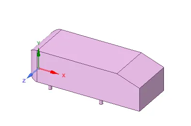
- After importing the model convert the units from millimetres to meters.
- Navigate to prepare and click on the enclosure and select the Ahmed body. Enter the enclosure dimensions as shown in the below snap. And uncheck symmetric option before giving the value.
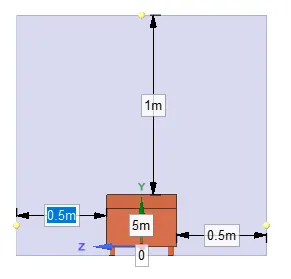
- After creating the enclosure, we have to create another enclosure so that we could create a finer mesh in that part and acquire a better wake formation region.
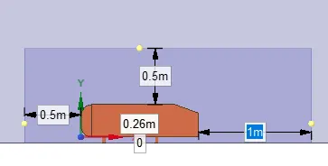
- After creating the enclosure, check whether there is an interference between the created enclosures.
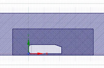
- We could observe there is an interference between the created enclosures. So the interfernce have been solved by using the following steps. Prepare --> Interference --> Select the Green Tick option.
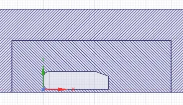
- After clearing the interference, we can now split the body in half using the split body command in design by selecting the XY plane. choose split body and choose the enclosure needed to split, select the plane and choose the part needed to be removed. Similarly, we can achieve split on both the enclosures and the body.
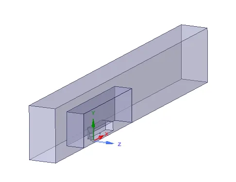
- After splitting the geometry, hide and suppress the physics of the Ahmed body and go to properties and select Share topology. Now the mesh from both the enclosures can share the information and have a symmetry.
Mesh:
- For meshing the model, open the mesh parameter. We first select the entity by using the entity selection by using faces so that we can provide name for our entity selection.
- Select the faces and create the named selection as inlet, outlet, symmetry, Ahmed body as car wall.
- Create a baseline mesh and perform the changes needed.
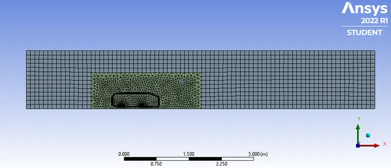
- In this case we have created a hexahedral meshing parameter for the outer enclosure and the element size is setup based on the case.
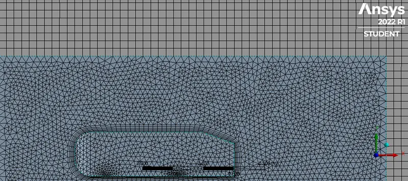
- In order to create a finer mesh in the inner enclosure region the element is changed according to the case. A face sizing option have been used to create a finer mesh around the Ahmed body legs.
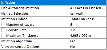
- Inflation layer have been used around the Ahmed body in order to capture the physics accurately and have a better mesh.
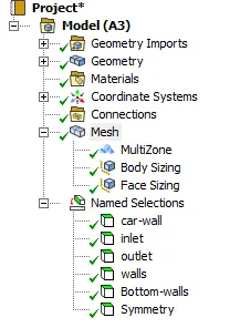
Case 1:
Outer enclosure: 100 mm (elemental size)
Inner enclosure:50 mm (elemental size)
Face sizing for Ahmed body :5 mm (elemental size)
Inflation for Ahmed body :6 layers with total thickness 49.6496 mm
Mesh Quality:
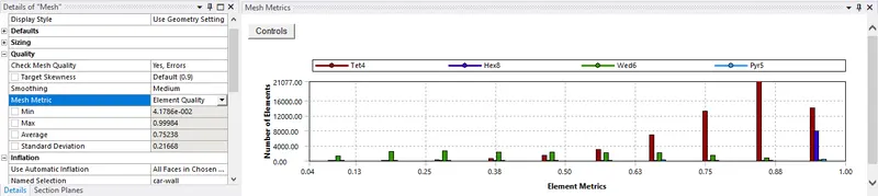
Mesh Statistics:
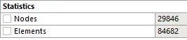
Fluent Setup:
- Once the meshing part is completed, close the mesh and update the mesh.
- Open the "Setup". Set the Solver Type as Pressure Based and Absolute under Velocity formulation.
- Under Models open Viscous select the k-epsilon model and click ok.
- Then under Material set the fluid to be air.
- Under Cell Zone Conditions make sure that the selected fluid is air.
- Select the Boundary Conditions parameter and set the boundary conditions for the created named selections.
Inlet:
Select the type to be velocity-inlet and assign the velocity.
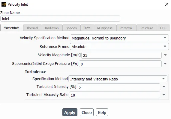
Outlet :
Pressure outlet: Gauge pressure = 0 pa
Car walls:
Wall: No slip
Symmetry walls:
Type: symmetry
Bottom wall:
Type: wall - No slip
Reference Value:
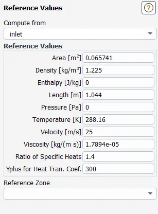
In the reference value select the compute from option as Inlet. The area is calculated by the following steps.
Results --> Reports --> Discrete Phase --> Projected Areas --> Select the car-wall surface --> compute
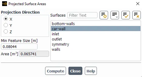
The characteristic length of the Ahmed body is calculated to be 1.044 m
After completing the above steps "Hybrid Initialisation" is done.
After initialize we should go to the post process to create a cut plane to see the velocity profile on it
And create a contour plot for both pressure and velocity
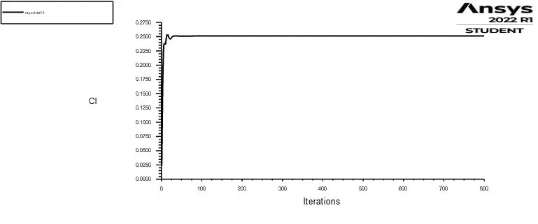
Also, create a plot for drag and lift using the definition tool
And give the reference values for the Ahmed body
Run the simulation for 500 iterations.
Results:
Residual Plot:

Drag plot:
Lift plot:
Velocity contour:
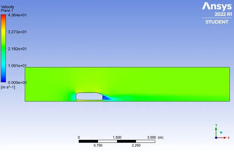
From the plot we could observe low pressure region formation at the front side of the Ahmed body. This is due to the stagnation of the fluid over the Ahmed body. When the stagnation occurs, the velocity is dropped and the pressure is increased. In the back end of the Ahmed body, we could observe the wake region as there is no way for the fluid to occupy the space when the body is in motion. The wake region formation is the main cause for the drag formation.
Pressure contour:
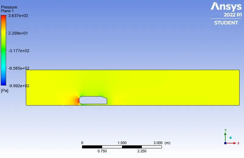
From the above contours, we could observe that the pressure increases drastically when the stagnation occurs which in turn decreases the velocity of the fluid. The high-pressure region is called as stagnation point.
Vector plot:
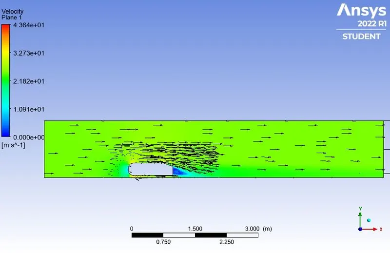
From the vector plot we could observe that the wake region have been formed at the rear end of the Ahmed body.
Velocity at different Y-locations:
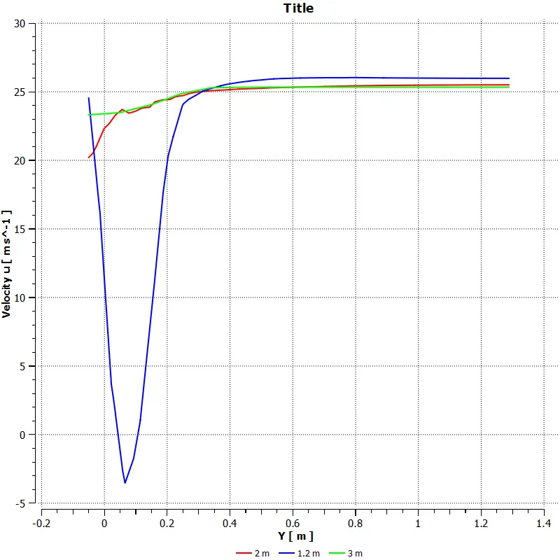
At the location of 1.2 m away from the origin which is at the wake region we could observe that there is a sudden drop in the velocity. This is happening because of the wake region formation at the rear end of the Ahmed body.
Case 2:
Outer enclosure: 90 mm (elemental size)
Inner enclosure: 40 mm (elemental size)
Face sizing for Ahmed body: 5 mm (elemental size)
Inflation for Ahmed body: 6 layers with total thickness 49.6496 mm
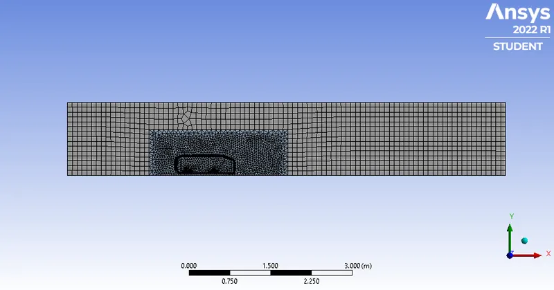
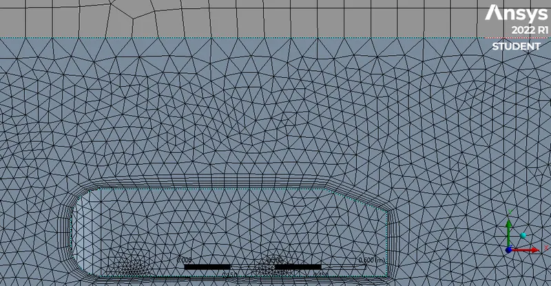
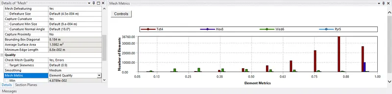
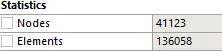
By following the same steps, only the element size of the outer and inner enclosure have been changed and the flow have been simulated.
Mesh:
Mesh Quality:
Mesh Statistics:
Results:
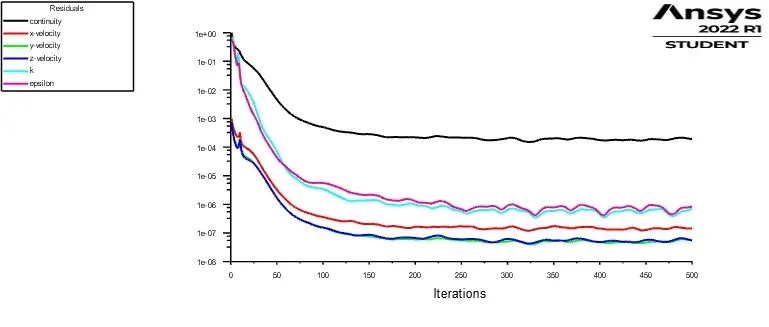
Residual Plot:
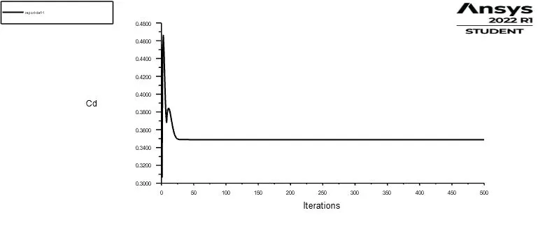
Drag plot:
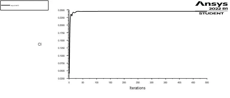
Lift plot:
Velocity contour:
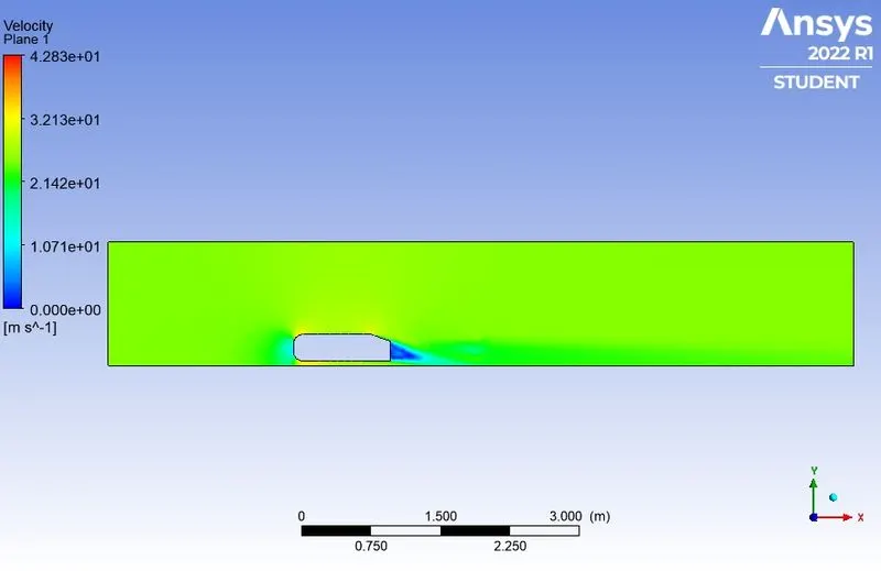
From the plot we could observe low pressure region formation at the front side of the Ahmed body. This is due to the stagnation of the fluid over the Ahmed body. When the stagnation occurs, the velocity is dropped and the pressure is increased. In the back end of the Ahmed body, we could observe the wake region as there is no way for the fluid to occupy the space when the body is in motion. The wake region formation is the main cause for the drag formation.
Pressure contour:
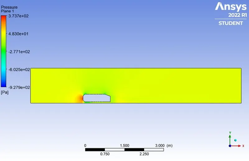
From the above contours, we could observe that the pressure increases drastically when the stagnation occurs which in turn decreases the velocity of the fluid. The high-pressure region is called as stagnation point.
Vector plot:
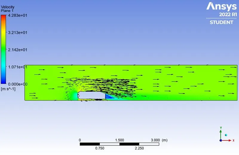
From the vector plot we could observe that the wake region have been formed at the rear end of the Ahmed body.
Velocity at different Y-locations:
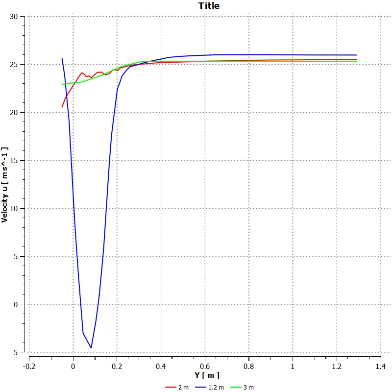
At the location of 1.2 m away from the origin which is at the wake region we could observe that there is a sudden drop in the velocity. This is happening because of the wake region formation at the rear end of the Ahmed body.
Case 3:
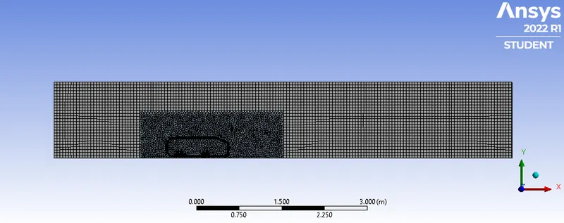
Outer enclosure: 50 mm (elemental size)
Inner enclosure: 30 mm (elemental size)
Face sizing for Ahmed body: 5 mm (elemental size)
Inflation for Ahmed body: 6 layers with total thickness 49.6496 mm
By following the same steps, only the element size of the outer and inner enclosure have been changed and the flow have been simulated.
Mesh:
Mesh Quality:
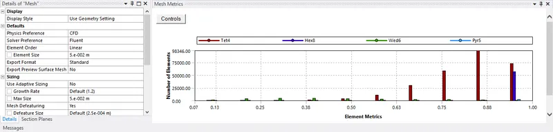
Mesh Statistics:

Results:
Residual Plot:
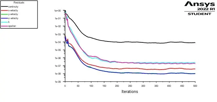
Drag plot:
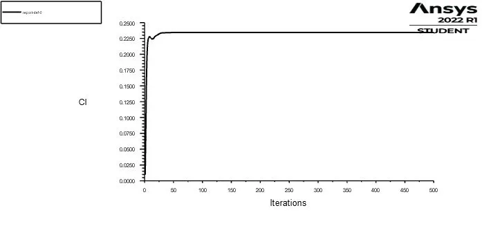
Lift plot:
Velocity contour:
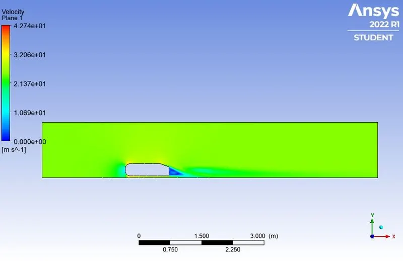
From the plot we could observe low pressure region formation at the front side of the Ahmed body. This is due to the stagnation of the fluid over the Ahmed body. When the stagnation occurs, the velocity is dropped and the pressure is increased. In the back end of the Ahmed body, we could observe the wake region as there is no way for the fluid to occupy the space when the body is in motion. The wake region formation is the main cause for the drag formation.
Pressure contour:
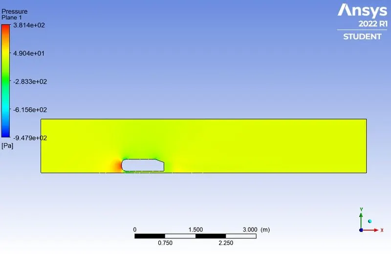
From the above contours, we could observe that the pressure increases drastically when the stagnation occurs which in turn decreases the velocity of the fluid. The high-pressure region is called as stagnation point.
Vector plot:
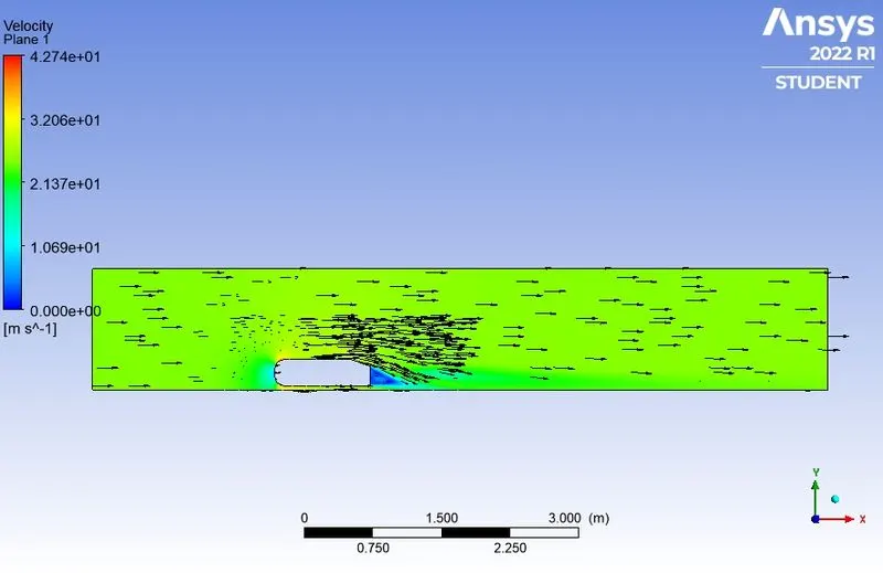
From the vector plot we could observe that the wake region have been formed at the rear end of the Ahmed body.
Velocity at different Y-locations:
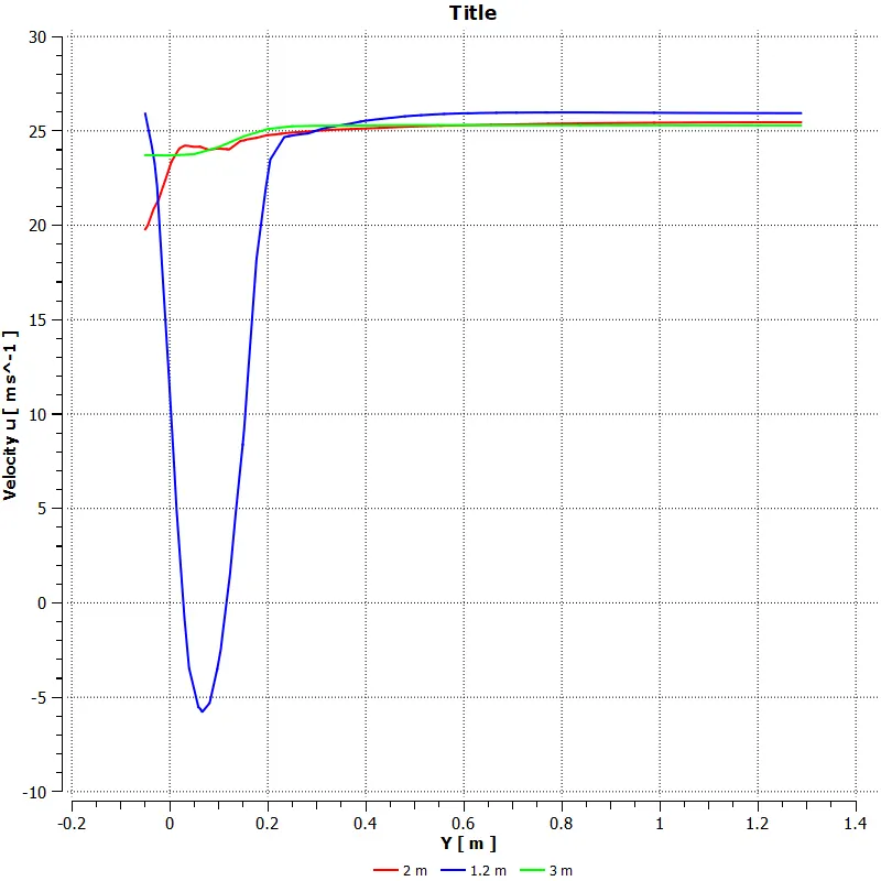
At the location of 1.2 m away from the origin which is at the wake region we could observe that there is a sudden drop in the velocity. This is happening because of the wake region formation at the rear end of the Ahmed body.
Results:
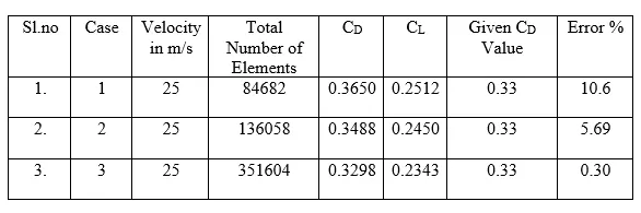
From the above table with the refinement of the mesh drag coefficient approaches closer to the analytical values that are because more cells are assigned at the boundary layer which results in more accurate results of drag coefficients.
Conclusion:
- The flow around the Ahmed body was simulated using Ansys Fluent.
- The virtual wind tunnel was setup using SpaceClaim.
- The flow over a slant angled Ahmed body is simulated.
- The contours for velocity and pressure profiles are displayed.
- From the contour plot we could conclude that the pressure is more on the front side of the Ahmed body, that happened because of stagnation point. A wake region could be observed at the backside of the Ahmed body in which there is no way for the fluid to reach the region.
- The velocity is low on the backside of the Ahmed body and the flow is recirculated behind the body because of the slant angle.
- The drag and lift forces are calculated and compared with the given data.
- In the above table we can observe that as we are refining the mesh, we can see that we are getting closer to the experimental value of drag co-effcient and the % of error is decreasing.
- So, it is better to use small mesh size but the thing is with the decrease in the grid size there will be increase in computational effort.